0925-9635/03/$ - see front matter䊚 2003 Elsevier Science B.V. All rights reserved. doi:10.1016/j.diamond.2003.08.024
Catalyzed growth model of carbon nanotubes by microwave plasma
chemical vapor deposition using CH and CO gas mixtures
4 2Mi Chen *, Chieng-Ming Chen , Horng-Show Koo , Chia-Fu Chen
a, b a bDepartment of Chemical Engineering, Minghsin University of Science and Technology Hsinfong, Hsinchu 304, Taiwan, ROC
a
Department of Materials Science and Engineering, National Chiao-Tung University, Hsinchu 30049, Taiwan, ROC
b
Abstract
Catalyst growth carbon nanotubes(CNTs) have been synthesized successfully by microwave plasma chemical vapor deposition
using CH –CO gas sources, and Fe, Ti, Fe4 2 yTi as catalysts. Significant difference of morphology in the carbon deposition was
observed between Fe and Ti catalyst. By adjusting growth parameters of CH to CO , a high yield of vertically aligned CNTs4 2
can be found in an Fe-deposited substrate. Ti is shown to be not suitable as a catalyst in CNT production. In the present work, we investigated the effect of H plasma pretreatment on the CNT growth from the viewpoint of catalyst morphology, using Fe as2
the catalyst. After the H pretreatment, significant catalyst particle sintering was observed and resulted in a broad size distribution2
of catalyst particles. The diameter of CNTs was governed by the catalyst particle size. The diameter of CNTs thus increased as the H plasma pretreated time increased. The CNT diameters were distributed in the range approximately 10–20 nm when Fe-2
deposited substrate was not pretreated. However, the diameter of CNTs increased from 30 to 300 nm when Fe-deposited substrate was pretreated from 1 to 15 min. The CNT growth model in catalysts, as a function of a gas environment of CH –CO gas4 2
mixture, was investigated.
䊚 2003 Elsevier Science B.V. All rights reserved.
Keywords: Carbon; Catalytic process; Plasma; CVD
1. Introduction
Microwave plasma chemical vapor deposition
(MPCVD) has been widely used for the growth of
carbon nanotubes (CNTs) and diamond film in H and2 CH , H and C H . Since CNTs were discovered by4 2 2 2 Iijima w1x, many kinds of synthetic techniques have been developed, such as arc discharge, laser ablation, pyrolysis, plasma-enhanced chemical vapor deposition, thermal chemical vapor deposition w2–7x. Some groups emphasized the control of CNT orientation and synthe-sized well-aligned CNTs by chemical vapor deposition for various catalysts, gas sources and substrates. Dai et al. w8x and Fonseca et al. w9x have studied the use of Fe, Mo, Co, Ni as catalyst particles particularly on Si-and Al-based substrates. The catalyst, reaction temper-ature and reaction gas play important roles for controlling growth quality of CNTs. Larger-size catalyst
*Corresponding author. Tel.: 3-5712121x55346; fax: q886-3-5724727.
E-mail address: [email protected](M. Chen).
particles with low density and broad diameter are formed at higher temperatures w10x. Rodriguez w11x and Jose-Yacaman et al. w12x have showed that the diameter of tubes was controlled by the metal catalyst particles, which activate CNT growth. Kukovitsky et al. w13x investigated the correlation between metal catalyst par-ticle size and CNT growth. Some groups reported pretreatments as a means of varying and controlling the diameter of CNT and investigated the effect of metal and the mass production methods w14–16x.
In our previous studies, MPCVD was successfully used to synthesize multi-walled CNTs by carbon oxide and methane gas mixtures w17x. We found that by substituting carbon oxide for hydrogen in CH –CO gas4 2 mixture, a high yield vertically aligned multi-walled CNTs could be synthesized at temperatures below 330
8C w18x. We also have investigated the correction
between temperature and diameter of CNTs w19x. The diameter of CNTs is influenced by the original catalyst-deposited size at low temperatures. Even at low temper-atures, a high yield of CNTs with a high emission current density and small diameter was obtained.
Table 1
The metal catalyst component
Catalyst Ti(%) Fe(%) Carbon component Quality
1 100 0 Carbon nanocones Poor
2 0 100 CNTs Good
3 50 50 A graphite sheets, CNTs Fair
Table 2
Experimental condition for H plasma pretreatment2
No. H plasma2 CH4yCO2 Microwave Pressure Deposition DC bias
pretreatment time(min) (sccm) power(W) (Torr) time(min) (V)
A1 0 30y30 300 15 20 y200
A2 3
A3 7
A4 15
In the present work, the effect of various catalysts on CNT growth was studied. The CNTs were deposited from CH and CO gas mixtures by MPCVD process4 2 using Fe, FeyTi, Ti catalyst, respectively. We
investigat-ed the H2 plasma pretreatment effect on Fe-catalyst morphology and the diameter of CNTs is controlled by the metal catalyst particles. Then, a CNT growth model in catalysts and gas environment of CH –CO4 2 gas mixture was investigated.
2. Experimental
2.1. The effect of various catalysts on CNT growth The metal catalyst nanoparticles were deposited on n-type Si(1 0 0) wafer by electron-gun metal evaporation of 10 nm. All metal components are listed in Table 1. The experiments were carried out in a MPCVD reactor. The 20=20 mm deposited metal-catalyst substrate was2 pretreated using hydrogen gas with the flow rate of 200 sccm. The microwave power was maintained at 300 W and the total pressure at 15 Torr.
2.2. Effects of H2 plasma pretreated on Fe-catalyst morphology
The Fe-catalyst nanoparticles were deposited on n-type Si (1 0 0) wafer by sputtering method. The
thick-ness of Fe catalyst was 10 nm. The experiments were carried out in an MPCVD reactor. The 20=20 mm2 deposited metal-catalyst substrate was pretreated using hydrogen gas with a flow rate of 200 sccm. The H -2 pretreated time was adjusted from 0 to 15 min. The microwave power was maintained at 400 W and the total pressure at 15 Torr. After the H plasma pretreat-2 ment, part of the substrate was cut and an atomic force microscope (AFM) was used to examine the morphol-ogy of the Fe catalyst. The remaining part of the H -2 pretreated substrate was reloaded in MPCVD and a
mixture of CH and CO was used as a source gas. The4 2 gas flow rates of CH and CO were set at 30 sccm,4 2 and DC bias was set at y200 V and was performed to align the CNTs. The deposition conditions are summa-rized in Table 2.
After deposition, a scanning electron microscope
(Hitachi S-4700I) was used to examine the morphology
of vertically aligned CNTs. A high-resolution transmis-sion electron microscope (Philips Tecnai-20) was then
used to investigate the microstructure of CNTs. 3. Results and discussion
3.1. Effects of various catalysts on CNT growth
Table 1 shows various catalysts for the growth reac-tion of CNTs. The effect of each catalyst was investi-gated by keeping power at 300 W and total gas pressure at 15 Torr, while at constant CH and CO flow rate of4 2 30 sccm. The quality of samples is quite good with Fe-deposited substrate, but the vertically aligned carbon nanocones are best formed in Ti-deposited substrate. Vertically aligned CNTs can be obtained but granular ball-like graphite and sheet-like amorphous carbon also appeared on the substrate. The yield of CNTs was less than 20%.
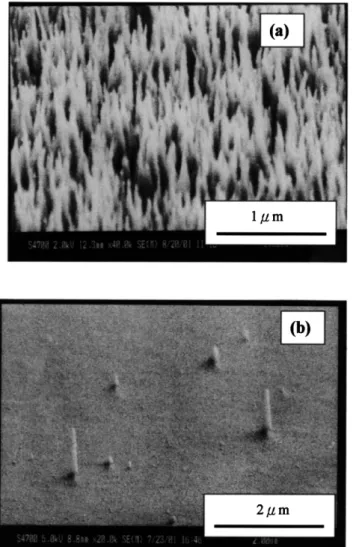
Fig. 1 shows the morphology of carbon deposited using different metal catalysts. Fig. 1a shows the SEM image of CNTs. It can be seen that the CNTs, which were grown on Fe-deposited substrate, are well aligned. Fig. 1b shows the SEM image of the carbon nanocones that were grown on the Ti-deposited substrate, with a negligible amount found. Ti is thus not suitable as a catalyst in CNT production. The FeyTi-deposited
sub-strate could be used to grow CNTs but the yield was low. It is likely that if the experimental conditions were optimized, the yield of CNTs can be improved. However, the yield and quality of CNTs strongly depend on the preparation conditions.
3.2. Effects of H2 plasma pretreated on Fe-catalyst morphology
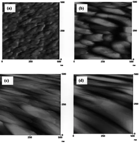
Fig. 2 shows the typical AFM morphologies of the catalyst particles obtained by the H plasma pretreat-2 ment. Fig. 2a shows the microstructure of catalyst surface film before the H plasma pretreatment of the2
Fig. 1. The morphology of carbon deposited using different metal catalysts.(a) SEM image of CNTs that were grown on the
Fe-depos-ited substrate. (b) SEM image of the carbon nanocones that were
grown on the Ti-deposited substrate.
sample. It indicates that Fe particles might be covered with oxide and the surface of particle is not smooth. Fig. 2b shows the Fe-deposited catalyst surface with H plasma pretreated for 3 min. It can be seen that the2 particle surface becomes smoother and agglomerated due to catalyst sintering. Fe particles stuck together after H plasma pretreatment, leading to a broad size distri-2 bution. The Fe particle changed from an approximately spherical to elliptic shape. Fig. 2c and d are the SEM images taken on the Fe-deposited catalyst surface of samples A3 and A4 pretreated with H plasma for 72 min vs. 15 min. Fig. 2c shows that the Fe-catalyst particles on the substrate have become agglomerated. The catalyst particles become longer and more crowded than that for sample A2, and clearly uniform in width. Fig. 2d shows that the particles sintered together were all longer than 200 nm and wider than A3. Hence, the sintering trends of the Fe particle catalytic nanoparticle,
due to the increased H plasma pretreatment time, can2 be observed.
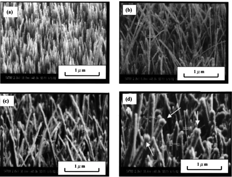
3.3. Effect of H plasma pretreatment on CNT growth2 Fig. 3 shows typical SEM morphology image of vertically aligned CNT growth on an Fe-deposited sub-strate. Fig. 3a shows SEM image without H plasma2 pretreatment. It shows the high density and aligned CNTs with diameter approximately 10–20 nm. Further identification of the diameter of CNTs still relies on the observation of high-resolution transmission electron
microscopy(HRTEM).
Fig. 3b with H plasma pretreatment for 3 min shows2 CNTs with diameter of approximately 25–35 nm without 100% vertically aligned as in Fig. 3a. Fig. 3c with H2 plasma pretreatment for 7 min shows that the size of non-uniform CNTs is of a diameter distributed in the range of approximately 40–90 nm.
Fig. 3d shows SEM image pretreated with H plasma2 for 15 min. It indicates that the CNTs also are not of uniform size. The diameter is distributed in the range of some 100–200 nm. The Fe particles encapsulated on the tip of CNTs are shown by white arrow in Fig. 3d. The catalyst particle size is clearly larger than the diameter of CNTs.
The relationship between the diameter of CNTs and the H2 pretreatment time is plotted in Fig. 4. It is illustrated that the diameter of CNTs rose with increased H pretreatment time. After the H plasma pretreatment,2 2 the shape and size of Fe particle clearly change. The results prove that the size of catalyst always determines the diameter of CNTs in chemical vapor deposition growth, concluded already by Choi et al. w20x.
3.4. HRTEM morphology images of CNTs
Further identification and analysis of CNT growth mechanism still rely on the observation and studies of HRTEM.
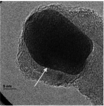
Fig. 5 is the HRTEM image for the multi-walled structure of sample A1 and exhibits the Fe particle encapsulated tip with the diameter of ;6 nm as shown by white arrow a. The diameter of CNTs is approxi-mately 18 nm and the thickness of CNT wall is approximately 5 nm. A hollow tube with 3-nm diameter and next to a compartment layer is indicated by white arrow b. Arrow c shows a compartment connection with the walls. The Fe particle is of approximately spherical shape. The Fe particle that takes part in various reaction paths of decomposition, diffusion, growth and deposition finally results in the growth of vertical CNTs.
Fig. 6 is the HRTEM image for the multi-walled structure of sample A2. It exhibits the Fe particle encapsulated tip with the diameter of approximately 30 nm, as shown by white arrow. The Fe particle has
Fig. 2. AFM image with the H plasma pretreatment.2 (a) Catalyst surface film before H plasma pretreatment of sample. (b) Pretreated with H2 2
plasma for 3 min.(c) Pretreated with H plasma for 7 min. (d) Pretreated with H plasma for 15 min.2 2
changed from approximately spherical to the almost elliptic shape. The diameter of CNTs is approximately 30 nm and the thickness of CNT wall is approximately 5 nm. The diameter of Fe-catalyst particle is similar to the diameter of CNTs. Thus, the CNTs grow along the grain of Fe particle, following the trend that the diameter of CNTs is determined by the Fe grain size. The H2 plasma pretreatment causes the sintering of the Fe particle catalytic nanoparticles, resulting in a cluster of CNTs and a blunter morphology.
3.5. Growth model of carbon nanotubes
Many various growth mechanisms have been illus-trated w21–23x; reaction sequences of deposition, adsorp-tion, decomposiadsorp-tion, diffusion, growth and deposition vary according to the reaction conditions and species during plasma processing.
A growth model of CNT growth model is speculated in the following text.
Fig. 7 shows the schematic diagram of the growth model of multi-walled CNTs. The CNT growth on Fe particle occurs by the following five steps:
(a) Carbon is disassociated from the CH –CO source4 2 gases, and deposited toward the surface of Fe particle, where a physical absorption of carbon atoms occurs.
(b) After carbon absorption, a saturated carbon film
is formed from the continuous decomposition of source gas and it encapsulated the metal catalyst.
(c) The catalyst and substrate surfaces were saturated
with carbon layers, and Fe catalyst was pushed upward due to the diffusion and osmotic pressure, depositing carbon into the graphite structure below the Fe catalyst. When carbon encapsulated Fe particles move quickly upward by continuous osmotic pressure, a core is formed below Fe-catalyst particles because the carbon source is
Fig. 3. SEM morphology image of vertically aligned CNT growth on an Fe-deposited substrate.(a) SEM image without H plasma pretreatment.2
(b) Pretreated with H plasma for 3 min. (c) Pretreated with H plasma for 7 min. (d) Pretreated with H plasma for 15 min.2 2 2
Fig. 5. HRTEM image for the multi-walled structure of sample A1.
Fig. 7. Growth model of multi-walled CNTs.
Fig. 6. HRTEM image for the multi-walled structure of sample A2.
unable to diffuse. The wall of CNTs was formed and rolled up in spherical and cylindrical shapes, and then hollow CNTs grow under the induction of Fe particle. CNTs are induced by DC bias to grow vertically.
(d) Carbon species were continuously supplied and
diffused into the growing CNTs. The CNTs in the lateral direction with multi-walled structure occur due to the additive precipitation of carbon species, with mutual reaction of hydrogen and oxygen, resulting in
multi-walled CNTs. Carbon generated from the decomposition of CH4 and CO2 surrounds the outer tube wall and keeps on growing in the direction of catalysts due to the continuous carbon supply, forming multi-layer tube walls.
(e) Settlement of the deposited graphite on the inner
tube walls induced by catalysts in the axial direction is graduated.
4. Conclusions
In summary, the MPCVD technique was adopted to grow aligned CNTs on Fe-deposited silicon substrates using CH –CO gas mixture. Fe particles cohered after4 2 H plasma pretreatment, leading to a broader size distri-2 bution. The Fe particle changed from approximately spherical to the elliptic, further elongating to elliptic shapes in non-uniform size. The diameter of CNTs was
approximately 15 nm, made without H plasma pretreat-2 ment, and 25–35, 40–90 and 200–300 nm for those pretreated with H plasma for 3, 7 and 15 min, respec-2 tively. Hence, it can be concluded that the diameter of CNTs is controlled by the metal catalyst particle size in chemical vapor deposition growth. On the other hand, a significant difference in morphology in the carbon dep-osition was observed between Fe and Ti catalysts. By adjusting the growth parameters of CH to CO , a high4 2 yield of vertically aligned CNTs was achieved for Fe-deposited substrates, but Ti was found to be not suitable as a catalyst in CNT production. Accordingly, on the basis of the experimental results, a possible growth model of multi-walled CNTs on Fe-deposited substrate was proposed.
Acknowledgments
The authors thank the National Science Council of Republic of China, Taiwan, for supporting this research under contract No. NSC89-2216-E-009-042. Technical support from the Semiconductor Research Center of National Chiao Tung University and National Nano Device Laboratory of NSC are also acknowledged. References
w1x S. Iijima, Nature 354(1991) 56.
w2x R. Stevens, C. Nguyen, A. Cassell, L. Delzeit, M. Meyyappan,
J. Han, Appl. Phys. Lett. 77(2000) 3453.
w3x X.K. Wang, X.W. Lin, V.P. Dravid, J.B. Ketterson, R.P.H.
Chang, Appl. Phys. Lett. 66(1995) 2430.
w4x L.C. Qin, D. Zhou, A.R. Krauss, D.M. Gruen, Appl. Phys.
Lett. 72(1998) 3437.
w5x Z. Shi, Y. Lian, X. Zhou, et al., Carbon 37(1999) 1449. w6x Z.P. Huang, J.W. Xu, Z.F. Ren, J.H. Wang, M.P. Siega, P.N.
Provencio, Appl. Phys. Lett. 73(1998) 3845. w7x C.J. Lee, J. Park, Carbon 39(2001) 1891.
w8x H.J. Dai, A.G. Rinzler, P. Nikolaev, A. Thess, D.T. Colbert,
R.E. Smalley, Chem. Phys. Lett. 260(1996) 471.
w9x A. Fonseca, K. Hernadi, P. Piedigrosso, et al., Electrochem.
Soc. 97(1997) 884.
w10x C.J. Lee, J. Park, Y. Huh, J.Y. Lee, Chem. Phys. Lett. 343 (2001) 33.
w11x N.M. Rodriguez, J. Mater. Res. 8(1993) 3233.
w12x M.J. Yacaman, M.M. Yoshida, L. Rendon, J.G. Santiesteban,
Appl. Phys. Lett. 62(1993) 657.
w13x E.F. Kukovitsky, S.G. L’vov, N.A. Sainov, V.A. Shustov, L.A.
Chernozatonskii, Chem. Phys. Lett. 355(2002) 497. w14x A.M. Benito, Y. Maniette, E. Munoz, M.T. Martinez, Carbon
36(1998) 681.
w15x A. Zhang, C. Li, S. Bao, Q. Xu, Micro. Mesoporous Mater. 29 (1999) 383.
w16x M. Jung, K.Y. Eun, Y.I. Baik, K.R. Lee, J.K. Shin, S.T. Kim,
Thin Solid Films 398(2001) 150.
w17x M. Chen, C.M. Chen, C.F. Chen, J. Mater. Sci. 37 (2002)
3561.
w18x M. Chen, C.M. Chen, C.F. Chen, Thin Solid Films 420–421C (2002) 230.
w19x M. Chen, C.M. Chen, S.C. Shi, C.F. Chen, Jap. J. Appl. Phys.
42(2002) 614.
w20x Y.C. Choi, Y.M. Shin, Y.H. Lee, et al., Appl. Phys. Lett. 76 (2000) 2367.
w21x C.J. Lee, J. Park, Appl. Phys. Lett. 77(21) (2000) 3397. w22x Y. Saito, T.J. Yoshikawa, Cryst. Growth 71(1993) 154. w23x M. Jung, K.Y. Eun, J.K. Lee, Y.J. Baik, K.R. Lee, J.W. Park,