1818 IEEE JOURNAL ON SELECTED AREAS IN COMMUNICATIONS, VOL. 14, NO. 9, DECEMBER 1996
Integral
er Control
em with
e
Delay
Po-Rong
Chang, Member, IEEE, and Bor-ChinWang
A b s t r a c t I n this article, we investigate the use of fuzzy logic control techniques for adaptive power control in a direct-sequence code-division multiple-access (DS/CDMA) cellular system over the mobile fading radio channels with propagation time delay. A fuzzy PI (proportional-plus-integral) control whose input vari- ables are the received power error and error change is introduced to determine each user transmitting power in order to simultane- ously equalize all users’ signal powers received at the base station and achieve better system stability and control performance. This control strategy can ensure long loop transmission delays without causing the system to become unstable. According to the well-known phase-plane method, the derivation of the fuzzy PI control has been carried out by analyzing the response areas, cross-over, and extreme points of the system step response with apriori knowledge of the dynamics of the CDMA mobile fading channels. For a long time-delay fading process, a methodology is
developed to modify the rule base to contain the delay information for reducing the deadtime effects of the process. Moreover, the additional advantages of fuzzy PI control over conventional control theories are: increased robustness in spite of interference and the ability to handle the time-delay process whose parameters are not accurately known. Simulation results show that a good performance can be achieved both in rms tracking error and traffic capacity by use of fuzzy PI power control, especially in poor interuser interference and long time delay conditions.
I. INTRODUCTION
N
recent years, the direct-sequence code-division multiple- access (DS/CDMA) technique has attracted great attention as an alternative digital wireless technology option for mobile and personal communications. This is due to its potential to support a large number of simultaneous users than can be supported by the conventional access schemes, i.e., frequency- division multiple-access (FDMA) or time-division multiple- access (TDMA) [1]-[4]. However, in mobile fading envi- ronment, the maximum number of users supportable in a DS/CDMA system is limited by multipath fading, shadowing, and near-far effects [l]. A number of power control methods have been proposed to minimize the effects of fading, shadow- ing, and near-far problems. The well-known average power control [3] which attempts to eliminate the slowly varying near-far and shadowing effects will be affected by the fast multipath fading process even assuming that every user moves at constant speed. To tackle this difficulty, a fixed-step power control which can accommodate the effects of rapid fadingManuscript received April 27, 1995; revised November 22, 1995. This work was supported in part by the National Science Council, Taiwan, R.O.C., under Contract NSC 85-2221-E009-067.
The authors are with the Department of Communication Engineering, National Chiao-Tung University, Hsin-Chu, Taiwan, R.O.C. , (email:
Publisher Item Identifier S 0733-8716(96)05241-9.
is proposed by Ariyavisitakul and Chang [ 3 ] . The fixed-step power control is performed at a higher rate than the rate of multipath fading. It is suggested that the power increment command updating rate is higher than ten times the maximum fading rate. The power increment IS determined on the basis of the deviation between the desired nominal power level and the signal level received at the base station. Then the user transmitting power is created by performing the sum of the past determined power increments. From the above control actions, it is concluded that the fixed-step control is a slight modification of the integral control. Unfortunately, Philips and Nagle
[5]
showed that the integral control may make it possible to become unstable since the integrator is actually an unstable system. Viterbi et al. [4] applied the same concept to their power control scheme, however, whose power increment is determined according to a bang-bang-like control policy. The bang-bang control policy involves switching the control input alternatively from one extreme to another, at precalculated switching times. However, the precalculated switching times are very sensitive to modeling error and noise. This would lead to large overshoot, long rise time, and large steady state error[6]. Usually, the power feedback control may have a round-trip propagation time delay which represents the time from when the mobile transmits to the time when a power adjustment can next be made to the mobile’s transmission. Thus, the base station must receive and process the received signal and send back a power control command. Holtzman [ 2 ] , [7] indicated that the power control performance will severely deteriorate when the time delay increases.
Sripada et al. [6] proposed a fuzzy logic control (FLC) to overcome the drawbacks of both the bang-bang control and integral control. Furthermore, Li and Gatland [E] showed that the rule base of FLC may be modified to contain the delay information so that the delay effects can be reduced. In the fuzzy logic control [9], [IO], the measured variables are represented as fuzzy variables. A representation of the control signals as a fuzzy variable is computed from the measurements using fuzzy logic. In essence, the FLC provides an algorithm which can convert the linguistic control strategy based on the characteristics of mobile radio channels into a power control strategy. By using the defuzzification, the fuzzy control decisions are converted to a crisp power command which is used to adjust the level of power step. To improve the controller performance further, a fuzzy PI (proportional- plus-integral) control [6], [ 171 is introduced to determine each user transmitting power in order to maintain all signal powers received at the base station nearly equal. The proportional term
CHANG AND WANG: ADAPTIVE FUZZY PROPORTIONAL INTEGRAL POWER CONTROL 1819
of fuzzy PI control will effectively increase bandwidth, im- prove transient response, and eliminate the system instability. However, its integral term forces the steady state error to zero. The fuzzy PI control has been derived by investigating both the transient step response and steady state behavior of the system with a priori knowledge of the dynamics of the mobile fading radio channels. The derivation of fuzzy PI control rules may be purely heuristic in nature and relies on the qualitative knowledge of process behavior [20]. An alternative process of determining the fuzzy PI control rules is the systematic phase- plane method [8], [I81 which will be described in Section IV. Since the mobile CDMA power control system has a time delay, the rule base can be readily updated to contain the delayed information for reducing the deadtime effects of the process. In contrast to phase plane method, it is hard to derive the rule base for the time-delayed CDMA system by the heuristic method [20]. In Section V, two look-up tables based on control rules are introduced to perform the fuzzy PI power control at a sampling rate that is higher than ten times the fading rate. The coarse table is used to shorten the settling time The other table carries out fine tuning in order to yield the minimum steady state error. In Section VI, simulation results show that the proposed fuzzy PI power control is able to reduce the deadtime effect of a time-delayed fading process, and achieves better performance than the fixed-step approach.
11. ADAPTIVE FUZZY PI POWER CONTROL FOR A
CELLULAR CDMA SYSTEM WITH TIME-DELAY Fig. l(a) shows the overall schematics of a closed-loop power control system with two different types of time delays called the reverse- and forward-link delays. The reverse-link delay,
r,,
is equal to the mobile-to-base transmission delay, and the forward-link delay ~f is the sum of the processing time and base-to-mobile transmission delay. The power controller sends a power adjustment command via a forward-link channel with a delay ~f to the mobile unit. Therefore, the delayed power command would activate a linear power actuator ofthe mobile unit which can drive its own power amplifier and then transmits a signal power via a reverse-link mobile fading channel with delay -7r back to the base station. Note that the
mobile’s power actuator acts as a remote actuator controlled by a controller placed at the base station. However, this particular control scheme is not a standard scheme commonly used in the conventional control theory. Therefore, it should be changed to become a standard control scheme for easily analyzing its control property and performance. Fortunately, the power actuator module and forward link delay module are interchangeable in order (commutative) since both subsystems are linear. This would lead to a standard closed-loop control system shown in Fig. l(b) whose plant is a combination of the reverse-link fading channel and an equivalent reverse- link delay module with a new time lag, T = ~f
+
r,,where T is called the round-trip or loop time delay and equals the sum of the processing time and two-way signal propagation delay between mobile and base station. Moreover, Holtzman [7] addressed how well can the conventional closed- loop power control in the reverse link direction be done?
He gives estimates of the ability the feedback controller to effectively combat Rayleigh fading for mobiles. This controller is assumed to adjust the reverse link transmitting power at time instant
t
based on a perfect (noiseless) measurement of the received power at timet--7
seconds, and the power adjustment command is then sent to the mobile’s power actuator directly without being corrupted by any forward-link channel noise. For this feedback power control, Holtzman [7] showed that(1) where R( r) denotes the normalized autocovariance function of each mobile’s power before feedback control, q is the minimum reduction factor, o, and ouc represent the rms errors in controlled power and in uncontrolled power, respectively. The minimum reduction factor is equal to 0.25 when -7
=
1 msand maximum Doppler frequency is 40 Hz (e.g., around 900 MHz, 30 mhp). The value of q becomes larger by increasing the time delay T since
R ( T )
becomes smaller. For example, at T = 4 ms, the minimum reduction factor q is 0.89. At extreme case, 7 approaches unity when R ( r ) becomes zero (uncorrelation!) by letting T be infinity. Thus, the round-trip time delay is always greater than the duration of most of the deep fades. In other words, the feedback power controller with a very long time lag cannot provide any performance improvement to CDMA systems. It is concluded that the performance of feedback CDMA power control system is significantly dependent on the time delay. The rms error is usually termed as global performance index in control systems. Next, we would like to discuss the local performance index like rise time, overshoot involved in the CDMA power controller.The power control for a CDMA system is used to equalize the absolute signal powers of CDMA users received at each base station. Thus, each received signal power will track a nominal step response
.(t)
= T d ,t 2
0. If T d = 0,the problem is called a regulator problem; if ~d
#
0, it is a special case of the asymptotic tracking problem [5]. For simplicity, the set point Td is usually set to be zero in decibels for the CDMA power control problem. The conventional controllers used in the regulatory problem are the commonly used PI (proportional-plus-integral) controller [SI, [6]. How- ever, the conventional PI control has certain limitations. For example, the rise time of the system using PI control could be reduced by increasing the controller gain. However, this results in increased overshoot. Facing the above problem, a fuzzy PI control is proposed to overcome this difficulty. The conventional approach to fuzzy PI controller design is to generate a fuzzy rule base based on the system states of error and error change, and the dynamics and time-delay behavior of the process, thus producing a two-input single- output control rule base. This would yield fast rise time, minimum peak overshoot and minimum steady-state error [9],[l 11. Moreover, Li and Lau [lo] have made an interesting comparison between a conventional PI controller and a fuzzy PI controller. They showed that the fuzzy PI controller is less sensitive to large parametric changes in the process and is comparable in performance to the conventional PI controller for small parametric changes. Recently, Li and Gatland [8]
introduced a fuzzy PI controller with a rule base containing the
d-1820
I
transmitting
IEEE JOURNAL ON SELECTED AREAS IN COMMUNICATIONS, VOL. 14, NO. 9, DECEMBER 1996
power I I
actuator delayed
power
received Base station adjustment
power command
I
I
I transmitting I Reverse link mobile fading channel power actuator power channel noiseI
Mobile unit LinearI
power controller PowerReverse link mobile fading channel z = z,
+
Zra
I I plant Mobile unitI
LinearI
%ward link channel noise Fig. 1.(b) Equivalent closed-loop power control system with a standard control scheme and a new reverse-link delay T = T ~ .
+
T J .(a) Overall schematics of a closed-loop power control system with reverse- and forward-link delays, e.g., T ? . , and 7 1 , and a mobile power actuator.
process time delay information to reduce the deadtiine effects of the process. In this paper, we will utilize Li and Gatland’s concept to design a fuzzy PI power controller for reducing the time-delay effects in CDMA systems.
A conventional PI control algorithm is given by
u ( t ) = k p e ( t )
+
ICI1
e ( t ) d t ( 2 ) whereu ( t )
is a control action at time instantt , e ( t )
equals the set point minus the process output, and IC, and k l are scaling gain factors. In digital implementation, its incremental forin is written as(3)
U k + l = U k
+
A U k + l A U k + 1 = k p h k+
k I ? kwhere Aek equals the current error minus the last error, and u k + 1 and Auk+l are the control and incremental control actions for the next time interval, e.g., k
+
l t h interval, respectively.Therefore, a practical fuzzy PI control is introduced as follows:
where
F{
.,
.} denotes the fuzzy’function that acts on the rules of the formCHANG AND WANC: ADAPTIVE FUZZY PROPORTIONAL INTEGRAL POWER CONTROL 1821 Set Point Power Defuuification Interface I
I
I Inference I I I1
EngineI
I
Control Power Increment-
I I I fomard link channelIn
(3,
(Ai,B,,
Ci) are linguistic terms defined in the next subsection.Fig. 2 illustrates the architecture of the power control system in conjunction with the fuzzy logic PI controller. Notice that all quantities are in decibels. Each user transmits a signal power p i dB via a CDMA channel with time delay which is updated by a step Ap dB every Tp s. In mathematical terms, the user transmitting power at the k
+
lth interval is given byThe extra loop delay lTp ( I : integer) represents the round- trip time delay T expressed in terms of Tp. During the kth period, the signal power received at the base station is
p',(=pk-,
+
QI,+
n,f) dB, where p ; dB is the received power,y~, dB is the channel link gain due to path loss, multipath fading, and shadowing, and
ni
denotes the noise resulted from total interference from all the other users within and outside the desired cell. Error equals the set point minus the signal power level (channel output) received at the base station. Error change equals the current received power error minus the last received power error. Since the interference power indB, where P i p l and G I , are expressed in linear units (W)
instead of
pi-l
and g k , and I I , represents the additive total interference power in linear units (W). This received signal power is compared to a desired set point level at the base station, where the desired nominal level is usually assumed to be 0 dB. After the fuzzy PI control, this power increment command is sent back to the user over the return channel. decibels is not additive, n: is then equal to 10 log( 1+
&
1
A. Basic Architecture of Fuzzy Logic Control Systems
The basic configuration of an FLC comprises four principle components: a fuzzification interface, a fuzzy rule base, an inference engine, and a defuzzification interface. The fuzzi- fication interface converts the input values of the both error and error change into suitable linguistic values which may be viewed as terms of fuzzy sets. The fuzzy rule base comprises a knowledge of the application domain and the attendant control goals. It consists of a fuzzy data base and a linguistic (fuzzy) control rule base. The fuzzy data base are used to define linguistic control rules and fuzzy data manipulation in an
FLC. The control rule base characterizes the control goals and control policy by means of a set of linguistic control rules. The inference engine is a decision-making logic mechanism of an FLC. It has the capability of simulating mobile radio channel based on fuzzy concepts and of inferring fuzzy control actions employing fuzzy implication and the rules of inference in fuzzy logic. The defuzzification interface converts fuzzy control decisions into crisp nonfuzzy (i.e., physical) control signals. Among the commonly-used defuzzification strategies, the center of area or fuzzy centroid defuzzification method yields a superior result [12]. These control signals are applied to adjust the level of power step in order to equalize the signal powers of all users received at base station.
A fuzzy set A in a universe of discourse, U is characterized
by a membership function ,rr~-4 which takes values in the interval [O, 11; that is, 7 n ~ : U ----f [0, I]. Thus, a fuzzy set A in U
may be represented as a set of ordered pairs. Each pair consists of a generic element TI, and its grade of membership function, i.e., A = { ( u , m ~ ( u ) )
1
*U E U } . A linguistic variable is characterized by a quintuple(x,
T ( z ) , U, G,ni)
in which z1822 IEEE JOURNAL ON SELECTED AREAS IN COMMUNICATIONS, VOL. 14, NO. 9, DECEMBER 1996 -18 -12 -6 0 6 12 18 -12 -8 -4 0 4 8 12 (a) (b) w44 LN MN SN 4 Z E SP MP LP -6 -4 -2 0 2 4 6
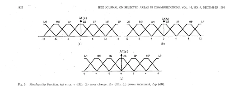
Fig. 3. Membership functlon: (a) error, e (dB); (b) error change, Ae (dB)
i.e., the set of names of linguistic values of 2 , with each value being a fuzzy variable denoted generically by 5 and ranging
over a universe of discourse U which is associated with the base variable U ,
G
is a syntactic rule for generating the name,X ,
of values of z, andM
is a semantic rule for associating with each X its meaning,a ( X )
which is a fuzzy subset of U .A particular
X ,
that is a name generated by G, is called a term. It should be noted that the base variable U can also be vector- valued. If z indicates the linguistic variable for the received power error of the power control system, then its term setT ( z )
may be chosen as {large positive (LP), medium positive (MP),
small positive (SP), zero (ZE), small negative (SN), medium negative (MN), large negative (LN)}. In addition, e represents the base variable for the power error in dB with its own universe of discourse E = {e
I
-18 dB5
e5
18 dB}. Thus,M
may assign a fuzzy set to the name of any term belonging to T ( z ) , e.g.,*(MP)
= { ( e , m M p ( e )1
e E E } whenX
is MP, where mMp(e) is a trapezoidal-shaped function shown in Fig. 3.111. CELLULAR CDMA
SYSTEM
MODELFor a cellular CDMA system, its service area is partitioned into a number of hexagonal shaped cells. For each cell, the CDMA system model consists of a number of K users, each having a mobile unit, all operating simultaneously through a
channel due to path loss, log-normal shadowing, and multipath fading. A base station, equipped with an m-branch antenna diversity combining, is placed at the center of the cell, and the mobile unit locations are uniformly distributed over the cell area.
Generally, the received signal via CDMA channel is affected by two types of fading: long-term fading, due to shadowing and path loss, and short-term fading, due to multipath prop- agation. Thus, the received power, P, W at the base station can be expressed as
where Pt is the transmitted signal power and G is the link gain due to channel model defined by
G = L . S (8)
(c) power increment, Ap (dB)
where
L
andS
are the long-term and short-term fadings, respectively. IfPt,
P,, and G can be expressed in dB units, and are denoted by pt,
p’, and g, respectively, thenpr = g + p t . (9)
The long-term fading L is mainly caused by the terrain configuration and the man-made environment between the base station and the mobile unit [ 131. The commonly-used model of
L is a product of a t h power of the distance and a log-normal random variable whose standard deviation is a dB and can be expressed
L
ATpa.
10t/lo (10)where
A
is a constant which depends on the parameters oftransmitter and receiver, T is the distance between the base station and the mobile unit, 01 is called the path loss exponent and
E
is a Gaussian random variable with zero mean and standard deviation 0 . In addition, the typical values of 0 anda are 8 dB and 4, respectively.
The long-term fading received signal is also called the local mean signal that has a probability density function (pdf) defined by
where CTL is the standard deviation (in natural log units) of L,
and
E
is the area mean signal at a receiver located at distanceT from a transmitter and equals AT-”.
Since the short-term fading S arises from the multi-path
propagation, Yao and Sheikh [ 141 showed that the distribution of S can be derived from the Nakagami-m distribution of
the path strength directly where the base station receiver uses m-branch antenna diversity combining. The fading on each branch is independently Rayleigh-distributed with a Doppler frequency spectrum corresponding to a uniform path arrival angle distribution. As a result, the distribution of the short-term fading for mth order diversity is given by
p ( S ) =
+)
1 2ms%xp(-2s)
2m (12)r ( m )
where l / m is the amount of fading, l / m =
~ar[u’]/E[(a’)]~,~
= E [ u 2 ] , and a is the received pathCHANG AND WANG: ADAPTIVE FUZZY PROPORTIONAL INTEGRAL POWER CONTROL 1823
strength due to the multipath fading. Sometimes, m may be called the diversity order.
For a specific mobile unit, its total interference power,
I
W from all the interfering mobile units within and outside the desired cell is then given by
KO-1 K ; l ) 12 K?
1 = p ; ~ r ( r k )
+
p j . , ( T j k )+
p ~ k ( ~ j k )k = l j=1 k = l j = l k = l
(13) where PTk(rjl;) denotes the received power at the desired base station due to a transmission by the kth mobile interferer (inside the j t h cell) at distance r j k from the desired base station,
KO
is the number of active mobile units in the desired cell andKjn)
is the number of active mobile units in cell jof tier
n(n
= l , j = 1 , 2 , . . . , 6 ; n = 2 , j = 1,2,...,12) of interfering cells surrounding the desired cell. The first term on the right hand side (rhs) of (13) represents the interference contribution from the other ( K O - 1) mobile units inside thedesired cell. Without loss of generality, the index of the desired cell is set to zero and also for the simplicity of notation,
F'&(.) = p,'(.), and TO^ = r k . The second and the third terms in (13) are the interference contributions from the mobile units inside the cells along the first and second tiers.
IV. DERIVATION OF FUZZY PI CONTROL RULES FOR A CDMA
SYSTEM WITH TIME-DELAY BY PHASE PLANE METHOD
The choice of the fuzzy control rules has a substantial effect on the performance of an FLC. There is a well-known phase plane approach to the derivation of fuzzy control rules [ 111. Prior to the derivation of fuzzy control rules, the fuzzy-set values or terms associated with the two input linguistic vari- ables, e and
Ae,
and the output control linguistic variable,Ap,
should be characterized, where e, Ae. and Ap are the received power error, power error change, and transmitting control power increment, respectively. The universes of discourse for e , A e and Ap are assumed to be E = {e
I
-18 dB5
e
5
18 dB},AE = {AeI
-12 dB5
Ae5
12 dB}, andA P = {Ap
1
-6; dB5
Ap5
6 dB}, respectively. Their associated term sets, T ( E ) . T ( A E ) , and T ( A P ) are identical and given by {LP (Large positive), MP (Medium positive),SP (Small positive), ZE (Zero), SN (Small negative), MN
(Medium negative), LN (Large negative)}; hence, there are 343 possible combinations of the terms generating a maximum possible 343 rules of the form ( 5 ) . Furthermore, the diagram- matic representation of those term sets, ? ? ( E ) , ??(LIE), and T ( A P ) are illustrated in Fig. 3(a), (b), and (c), respectively. Their associated membership functions are the commonly-used trapezoidal-shaped functions.
The phase plane approach proposed by King and Mamdani [ I l l is essentially a rule justification method. It involves tracking a desired closed-loop second-order system trajectory in a phase plane across the domain of the FLC so that the system trajectory can terminate on a desired state. The phase plane methods have been proven very useful in analyzing the stability and system performance criterion (e.g., overshoot,
I I
I 8
Id .I 1
Time
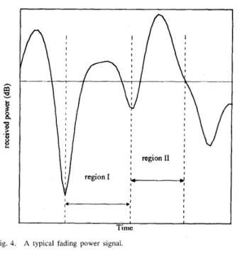
Fig. 4. A typical fading power signal
rise time, steady state error) of linear and nonlinear second- order systems. This technique was modified by Braae and Rutherford [ 1 S] by tracking the system trajectories through the linguistic phase plane instead of the real plane. For convenience of analysis, the general waveforms of a fading process are illustrated in Fig. 4. Observing a typical fading process, the envelope within region I can be modeled as
a portion of the step response of second order systems, since their dynamical behavior approximate5 a large class of practical systems [ 5 ] . In addition, the envelope belonging to region I1 is also characterized by a portion of the step response of another second order system with larger overshoot. From the above discussion, it is concluded that any fading process can be modeled as a piecewise second-order system. In other words, a combination of the primitive curves generated by second order systems with different local performance indixes can approximate the envelope of any fading process. Therefore, the control actions for the fading process are determined based on the behavior of second order systems. In the next subsection, we may derive a rule base in more rigorous manner using the phase plane method.
A. Rule Generation by Phase Plane Method
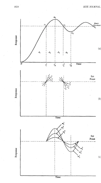
Fig. 5(a) shows the complete step response of a general open loop second-order process to be controlled, where the input variables of the fuzzy PI controller are the error ( e ) and error change (Ae). The output is the change of the process input (Ap). Typically an expert would consider the crossover and peak-valley or extreme points of the system step response and suggests appropriate control actions at each point to generate a closed-loop response with minimum peak overshoot, fast rise time, and zero steady state error. Moreover, the performance of the system is also dependent on its response areas. According to the magnitude of e and the sign of Ae, the response plane
1824 IEEE JOURNAL ON SELECTED AREAS IN COMMUNICATIONS, VOL. 14, NO. 9, DECEMBER 1996 e;: (e
<
0 + e>
0) e;: (e>
0 ---f e<
0) and Ae>>
0 and Ae<
0 e;: (e<
0 + e>
0) and Ae>
0. (15)V Both indixes 2 and denote the sign and amplitude of the
slope, respectively. For example, e; has a negative slope whose amplitude is larger than that of e;. In contrast, e: has a positive slope whose amplitude is also larger than that of e:.
In addition, the peak-valley index for representing the extent or degree of overshoot and undershoot is defined as
I l l I l l
8
d
I l l a Time,4
I I I I 1 I I I TimeFig. 5. General behavior of second-order system response: (a) response areas, (b) crossover points with six different index values, and (c) peak-valley points with six different index values.
is roughly divided into four areas
A l : e > O and A e < O A z : e < O and A e < Q
A3:
e<
0 and Ae>
0Aq:
e>
0 and Ae>
0. (14) For further increases in the resolution of the behavior representation, the response around the set point and the peak- valley points in Fig. 5(a) are emphasized in Fig. 5(b) and (c), respectively. The crossover index e: for identifying the slope behavior of the response across the set point (e zz 0) is definedas c;: ( e
>
0 --+ e<
0) e;: (e<
0 + e>
0) c:: (e>
0*
e<
0) and Ae<<<
0 and Ae>>>
0 and Ae<<
0 r n ; : A e = O and e < < < O r n ; : A e = O and e > > > O rn?: A e = 0 and e < < O m ; : A e = O and e > > 0 rn;;AezzO and e < Omi: Ae
0 and e>
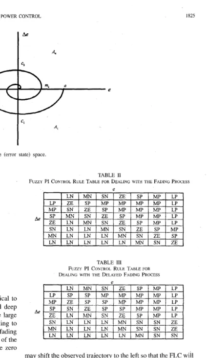
0. (16)For observing the error characteristics of (14)-( 16), the phase- plane trajectory corresponding to Fig. 5(a) is shown in Fig. 6.
The system equilibrium point is the origin of the phase-plane. The three types of indixes previously mentioned can be com- bined and shown in the rule base frame of Table I for reference, where the qualitative statements are quantized by using the fuzzy-set values as {LN, MN, SN, ZE, SP, MP, LP}. By
analyzing the phase-plane trajectory and Fig. 5(b) and (c), Li and Gatland [8] showed that there are several metarules used
to determine the control rules for response areas, crossover and peak-valley points. The rules for crossover points are that the control increment has the same sign as Ae and its magnitude is in proportion to l a e l , and the rules for peakvalley points are that the control increment has the same sign as e and its magnitude is in proportion to lei. For response areas, some observations used for determining control rules are made as
follows below.
1) At area
A I ,
the control rules should shorten the rise time when e is large and prevent the overshoot in A:!when e is close to zero. Thus, a positive large control increment is required to drive the closed-loop response toward the set point generating an improvement in the rise time when e is large, and the control increment is zero or negative in order to prevent the overshoot when the response approaches the set point.
2) At area
Aa,
the control rules should decrease the over- shoot around the peak above the set point. Thus, thecontrol increment must be negative.
3) Control rules for areas A3 and A4 are dual to that listed in (1) and ( 2 ) , respectively. For example, the control increment for A4 is positive in order to prevent the overshoot around the peak below the set point, and a
negative large control increment i s required for A3 when le1 is far away from zero.
More details about determining the control rules for re- sponse areas can be found in reference [XI. However, it should be mentioned that the shape of the fading process within area
Ad is much sharper than that of a second-order system. It is
CHANG AND WANG: ADAPTIVE FUZZY PROPORTIONAL INTEGRAL POWER CONTROL 1825
Fig. 6 . The mapping of the time domain response in phase plane (error state) space.
TABLE I
RULE BASE FRAME FOR PHASE PLANE METHOD
P
I
ILN MN SN ZE SP MP LPI
control increment for the downward deep fade is identical to that of area A4 shown in Fig.
34.
For the downward deep fade, the magnitude of the control increment should be large enough to drive the response back to set point. According to the above discussions, the linguistic control rules for the fading process are listed in Table 11. It is noted that the element of the fourth row and the fourth column is used to ensure the zero steady state error of the system response and given byR,: IF e is ZE and Ae is ZE THEN Ap is ZE. In other words, this rule has caused the closed-loop response to fall within a stable region around the set point with a set width of linguistic qualifier “ZE.”
B. Rule Modijication for a System with Time Delay
As mentioned in Section 11, the performance of the CDMA power control system is badly affected when it has a long time delay. To tackle this difficulty, it may be helpful to introduce some delay information into the rule base listed in Table 11.
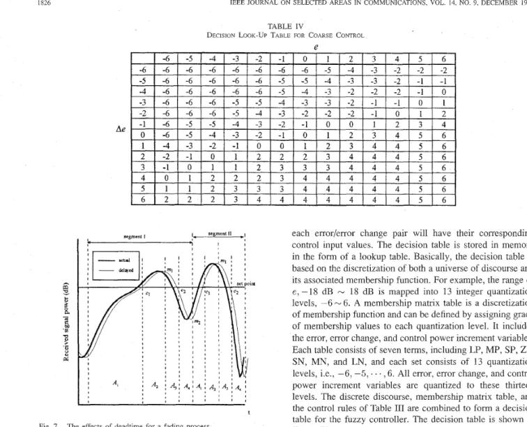
For simplified analysis, we are only interested in a portion of the fading process and its associated second-order system model, e.g., segment I or segment I1 in Fig.
7.
Usually, the FLC-based power controller should track its desired system trajectory illustrated in Fig. 7. However, the trajectory the FLC observes will fall behind the actual one when the system hasa significant time delay. To eliminate this deadtime effect, one
TABLE I1
FUZZY PI CONTROL RULE TABLE FOR DEALING WITH THE FADING PROCESS
e
Ae
TABLE 111
F U Z Z Y PI CONTROL RULE TABLE FOR
DEALING WITH THE DELAYED FADING PROCESS
may shift the observed trajectory to the left so that the FLC will track the actual trajectory. In the meantime, its four response areas A I N A4 and crossover and peak-valley points are also
shifted to the left. This is equivalent to shifting the observed trajectory at the bottom half of the phase plane
( A I
and A2:Ae
<
0 ) to the left, and the observed trajectory at the top half plane ( A 3 and A4: Ae>
0 ) to right. As shown in the above section, the three types of indixes in the phase plane can be mapped to a frame of the rule base. Thus, the left shift in the bottom half of phase plane is equivalent to shifting the bottom rules of Table I1 from left to right. Similarly, the right shift in the top half phase plane will result in the left shift of the top rules. The control rules for a typical delayed fading process is shown in Table I11 and used to reduce the delay effects. It should be mentioned that segmentI1
does not have the peak- valley point 7712 at the boundary of A4. For this case, only the control rules formi,
15
i
5
3 in Table 111 are disabled. However, the other control rules are still active. The control rules for A4 should especially take care of this situation. It1826 IEEE JOURNAL ON SELECTED AREAS IN COMMUNICATIONS, VOL. 14, NO. 9, DECEMBER 1996
Ae
TABLE IV
DECISION LOOK-UP TABLE FOR COARSE CONTROL
e
t
Fig. 7. The effects of deadtime for a fading process.
means that the control rules for a fading process are determined based on a combination of response areas, crossover indixes and peal-valley indixes even though some of them do not appear in the process.
V. IMPLEMENTATION OF FUZZY PI POWER In order to achieve the high power control command up- dating rate, it is expected to develop a high - speed hardware to implement our fuzzy PI controller. Fortunately, there are a lot of VLSI chips that have been designed for FLC's [I71
in order to achieve the real - time execution. An alternative cost-effective approach to shorten the running time of the fuzzy PI controller is to construct a set of look - up tables based on control rules and then to program it onto mask ROM chips. A decision table, relating quantized measurements to crisp control actions, can be generated off - line using control rules in order to speed up the FLC. In other words, the calculations of fuzzification, correlation - minimum inference,
and fuzzy centroid defuzzification can be performed on a computer based on the control rules. After the calculations,
CONTROLLER USING DECISION TABLE APPROACH
each error/error change pair will have their corresponding control input values. The decision table is stored in memory in the form of a lookup table. Basically, the decision table is based on the discretization of both a universe of discourse and its associated membership function. For example, the range of e, -18 dB N 18 dB is mapped into 13 integer quantization
levels, -6 N 6. A membership matrix table is a discretization
of membership function and can be defined by assigning grade
of membership values to each quantization level. It includes the error, error change, and control power increment variables. Each table consists of seven terms, including LP, MP, SP, ZE, SN, MN, and LN, and each set consists of 13 quantization levels, i.e., -6, -5, . . . , 6 . All error, error change, and control power increment variables are quantized to these thirteen levels. The discrete discourse, membership matrix table, and the control rules of Table I11 are combined to form a decision table for the fuzzy controller. The decision table is shown in Table IV.
Pedrycz [19] showed that the performance of the original decision table can be significantly improved by introducing a new decision table to perform fine control. The fine decision table would be active with finer quantization levels of control and resolution when (e,
Ae)
falls within a predetermined nested region. When (e, Ae) is outside the nested region, Table IV carries out the coarse control. In this application, the nested region is chosen as -3 dB N 3 dB for e and -6 dB-
6 dB forAe. The limit of A p is set between -3.6 dB and 3.6 dB. Their corresponding term sets are {SP, ZE, SN} for e , {MP, SP, ZE, SN, MN} for n e , and {MP, SP, ZE, SN, MN} for A p . Its associated decision table is shown in Table V. In summary, the coarse table is used to achieve the fast response. The fine table produces a minimun steady state error with a magnitude comparable to the width of the nested region.
VI. SIMULATION RESULTS
To verify the effectiveness of the proposed fuzzy PI power control, numerical values of the tracking error and conditional outage probability for a number of examples are calculated for a CDMA cellular system using Monte Carlo simulation. The following assumptions are made in the numerical computa-
CHANG AND WANG: ADAPTIVE FUZZY PROPORTIONAL INTEGRAL POWER CONTROL z
(:time
delay) f k z y PI fixed-step I827 - - --
2Tp 3 TP *P 2Tp 3 T pT,
3.84 4.53 5.52 3.38 3.95 4.78 6.05 6.76 7.44 5.45 6.08 6.96 TABLE VDECISION LOOK-UP TABLE FOR FINE CONTROL
Ae
4 3 3 3 3 3 3 3 4 4 4 4 5 5
5 4 4 4 4 4 4 4 4 4 4 4 5 5
6 5 5 5 5 5 5 5 5 5 5 5 5 5
TABLE VI
COMPARISON OF RMS TRACKING ERRORS ACHIEVED BY FUZZY PI CONTROL AND FIXEDSTEP CONTROL WHEN 7 1 ) = 2 OK 4, fnT,, = 0.05, AND r = TI, OR 2T, OK 3T,,
tions: 1) the service area consists of 19 hexagonal shaped cell, i.e., the desired cell is surrounded by two tiers of interfering cells: 2) all cells contain the same number of active mobile units, and the positipns of the active mobile units within each cell are uniformly distributed with a density of K users per base station; 3) interference reduction techniques such as cell sectorization and voice activity detection are not considered. It is believed that the improvements from these effects can be introduced through multiplicative factors; and 4) each user scans signals from the closest base stations and decides to communicate with the base station which has the largest local-mean signal power. This local-mean signal power was determined from path loss proportional to the fourth power of the propagation distance and simulated lognormal shadow fading with standard deviation of 8 dB.
The parameters of a proposed practical CDMA system are assumed in the calculations: The spreading bandwidth is 1.25 MHz and the user data rate is 8 kb/s which give a processing gain of approximately 22 dB. The required energy per bit to interference spectral density ratio, Eb/Io is selected as 7 dB (reverse-link). Using the calculated processing gain and the selected value of required &/Io, the required signal-to- interference ratio threshold, SIR,h is found to be -15 dB (reverse link). The sampling time period is set at Tp = 1.25 ms. For long-term fading, the path exponent, a is assumed
to be four and the standard deviation for shadowing is set at 8 dB. For short-term fading, f D T p is uniformly distributed between 0.01 and 0.05, where f o denotes the Doppler rate. The diversity order, rrb of Nakagami distribution is assumed to be either two or four. For simplicity, it is assumed that the power adjustment command from the base station is not corrupted by the forward-link channel noise. The CDMA
0 0 -10 0 -20 0 0 0
-
FUnyPlCalrm Pud-up c m t r d -20 0 -30.0 0 20 40 60 80 100 120 140 Time (T,)Fig. 8. Comparison of the waveforms of the received signals achieved by the fuzzy PI control and 1 dB fixed-step control when T = 2T,. 711 = 4,
~ D , T ~ , = 0.05, and the desired mobile unit is initially placed at position which causes a 20 dB path loss.
power control system has three different round-trip time delay situations, e.g., r = Tp or 2Tp or 3T,.
According to Li and Gatland's tuning strategy for control gains in FLC [8] there are two sets of control gains for our fuzzy PI power control system. One set of control gains, e.g.,
{ k,,
,
k l , } is used for a coarse control, to speed up transient response. When the error falls within preset limit, the second set of gains { k,,,
k ~ , } is used for a fine control, which can smooth the response around the set point. In our experiments,ICpi
,
k l ,,
IC,,,
k ~ , are chosen as 112, 113, I , and 2, respectively. Fig. 8 illustrates the waveforms of power-controlled signal1828 IEEE JOURNAL ON SELECTED AREAS IN COMMUNICATIONS, VOL. 14, NO. 9, DECEMBER 1996 TABLE VI1
COMPARISON OF RMS TRACKING ERRORS ACHIEVED BY FUZZY PI CONTROL A N D FIXED-STEP CONTROL WHEN I ) ? = 2 OR 4 , 7 = ZTll, AND for, = 0 025 OR 0 0375 OR 0 05
using both the fuzzy PI control and 1 dB fixed-step control when loop delay r = 2Tp, m = 4, and the desired mobile unit is initially placed at a position which causes a 20 dB path loss, and then moves at a Doppler rate f D , where f D T p = 0.05. A
comparison of these two waveforms in Fig. 8 indicates that the fuzzy PI control can achieve much faster rise time and smaller overshoot than the fixed-step control. For fuzzy PI control, coarse decision table of Table IV is applied to greatly reduce the large received power deviation at the initial time point and to quickly drive the received signal power level toward a
nominal 0 dB since this initial power deviation is resulted from the 20 dB path loss and total cochannel interference. Once the received power deviation becomes relatively small, Table V carries out the fine tuning in order to regulate the small short-term fading and interference powers. Coarse decision table will become active again when excessively deep fades or large interference powers occur. In contrast to the above fuzzy
PI control, the response of 1 dB fixed-step control is rather slow, and shows substantial overshoot and the oscillation. However, with the fuzzy controller engaged, the overshoot is drastically reduced and oscillation is effectively eliminated. Note that the rate of convergence of the fuzzy PI control is nearly the same as the rate of convergence of the proportional (nonfuzzy) controller. This may be due to the user transmitting signal power limitation. Comparing the magnitudes of those two waveforms at time instant, 150Tp, the fuzzy PI control achieves smaller steady state error than fixed step control. Furthermore, the performance of the power regulatory control can be characterized by a performance index called
r m s
tracking error. The rms tracking error is obtained by averaging the squared power error over a time window from the initial time point to 150Tp. The fuzzy PI control results in a rms tracking error (= 3.95 dB) which is much smaller than the rms tracking error (= 6.08 dB) of fixed-step control. The values
of the rms tracking errors are listed in Table VI for various assumptions of r and the order of diversity, nz at the base station receiver. The rms tracking errors with fuzzy PI control are always smaller than fixed-step control by a reduction ratio of about 31.8 (in average) % for rn = 2 or 30.2% for
rn
=4.
Next, we would like to give an example for describing the Doppler fading rate effect on the fuzzy PI control. Table VI1 shows a comparison of both power controls with a nominal time delay (T = 2Tp) for three different Doppler rates and two different orders of diversity. The rms errors of both control schemes become larger when the Doppler rate becomes larger. However, the fuzzy PI control still achieves the better rms
tracking performance than the fixed-step control.
0.40 f
6 8 10 I2
Number of w e n pm cdl
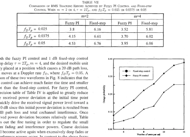
Fig. 9. Comparison of outage probabilities against the number of users per cell achieved by fuzzy PI control and 1 dB fixed-step control when 111 = 2 , T = 2T,, and SIRtb, = -15 dB
This conditional outage probability is usually recognized as a main criterion for the traffic capacity and communication quality of CDMA system since the capacity is defined as the maximum number of users per cell for which the outage probability is less than a specified value [16]. In a multicell CDMA system where the same spectrum is reused in every cell, it is reasonable to assume that the cochannel interference is much greater than thermal noise. Under this condition, the outage probability becomes the probability failing to achieve a required SIR threshold,
SI&,,
for quality communications, and is defined byoutage probability
d-
P,{SIR<
SIRth}. (17) Fig. 9 shows the conditional outage probability against the number of users per cell for fuzzy PI control and fixed-step control when the diversity order, m equals two and SIRth =-15 dB. In addition, each outage probability involved in the calculation of the conditional outage probability can be obtained by computing the ratio between the total time the received signal whose SIR is below SIRth (= -15 dB) and a time interval (=150Tp). Clearly from Fig. 9, the conditional outage probability increases with the active users per cell. Notice that the rate of increase is however more gradual when fuzzy PI control is used than when fixed-step control is used. The adoption of fuzzy power control also results in less conditional outage probability, e.g., the conditional outage
CHANG AND WANG: ADAPTIVE FUZZY PROPORTIONAL INTEGRAL POWER CONTROL 1829
probability with fixed-step control is reduced by up to 38%
(in average) when the fuzzy PI control is used. For the same number of active users, the conditional outage probability is smaller for fuzzy PI control than fixed-step control. Moreover, one may find that the conditional outage probabilities for both control schemes become smaller simultaneously if the order of diversity becomes larger, for example, m = 4. However, the fuzzy PI control provides much smaller outage probability than fixed-step control by an average reduction factor of 59%.
VII. CONCLUSION
This paper presents the development of a feedback power control based on fuzzy logic theory. The proposed fuzzy PI power control is able to keep all users’ signal power received at the base station nearly equal over the CDMA mobile radio channels with time delay. According to the phase plane method, its control rule base has been derived by analyzing the three local performance indixes of the CDMA fading proccss. Forty-nine fuzzy control rules have been found to
improve the controller performance. For a long delay fading process, the delayed information has been incorporated to reduce the deadtime effect of the process. For comparison of
simulation results, it can be seen that the fuzzy PI control can achieve faster rise time, small overshoot and better rms
tracking error than the fixed-step control. This better controller performance would lead to smaller outage probability and substantial capacity improvements. Simulation results show that the outage probability with fixed-step control is reduced up to 38% for m = 2 or 59% for m = 4 when the fuzzy PI control is used. This means that the fuzzy PI control is robust against interuser interference. It has been shown that, for a fading process with long deadtime, fuzzy PI power control can achieve a better performance than a fixed-step feedback power control.
REFERENCES
K. S. Gilhousen, I. M. Jacobs, R. Padovani, A. J. Viterhi, L. A. Weaver, and C. E. Wheatley, “On the capacity of a cellular CDMA system,” IEEE Trans. Veh. Technol., vol. 40, pp. 303-312, May 1991. F. Simpson and J. M. Holtzman, “Direct sequence CDMA power
control, interleaving, and coding,” IEEE J . Select. Areas Commun., vol. 11, no. 7, pp. 1085-1094, Sept. 1993.
S. Ariyavisitakul and L. F. Chang, “Signal and interference statistics of a CDMA system with feedback power control,” IEEE Trans. Commun., vol. 41, no. 11, Nov. 1993.
A. J. Viterbi, A. M. Viterbi, and E. Zehavi, “Performance of power controlled wideband terrestrial digital communication,” IEEE Trans. Commun., vol. 41, pp. 559-569, 1993.
C. L. Philips and H. T. Nagle, Digital Control System Analysis and Design.
N. R. Sripada, D. G. Fisher, and A. J. Morris, “AI application for process regulation and servo control setting,” IEE Proc., 1987, vol. 134, pt. D,
no. 4, pp, 251-259.
J. M. Holtzman, “CDMA power control~?or wireless network,” in Third Generation Wireless Znformation Nehvork, S. Nanda and D. J. Goodman, Eds.
H. X. Li and H. B. Gatland, “A new methodology for designing a fuzzy logic controller,” IEEE Trans. Syst. Man, Cyber., vol. 25, no. 3, pp. 505-512. 1995.
Englewood Cliffs, NJ: Prentice-Hall, 1984.
Boston, MA: Kluwer, 1992, pp. 299-311.
[9] C. C. Lee, “Fuzzy logic in control systems: Fuzzy logic controller-Part I & 11,” IEEE Trans. Syst. Man, Cyber., vol. 20, no. 2, pp. 404435,1990. [IO] Y. F. Li and F. C. Lau, “Development of fuzzy algorithm for servo systems,” lEEE Control Systems Mag., vol. 9, no. 3, pp. 65-72, 1989. [I 11 P. J. King and E. H. Mamdani, “The application of fuzzy control systems
to industrial processes,” Automarica, vol. 13, no. 3, pp. 235-242, 1977. [12] M. Braae and D. A. Rutherford, “Fuzzy relations in a control setting,”
Kybernetes, vol. 7 , no. 3, pp. 185-188, 1978.
[I31 W. C. Jakes Jr., Ed., Microwave Mobile Communications. New York: Wiley, 1974.
[I41 Y.-D. Yao and A. U. H. Sheikh, “Investigations into cochannel interfer- ence in microcellular mobile radio systems,” IEEE Trans. Veh. Technol., vol. 41, no. 2, pp. 114-123, May 1992.
[15] M. Zorzi and S. Pupolin, “Outage probability in multiple access packet radio networks in the presence of fading,” IEEE Trans. Veh. Technol., vol. 43, no. 3 pp. 604-610, Aug. 1994.
[16] R. Prasad, M. G. Jansen and A. Kegel, “Capacity analysis of a cellular direct sequence code division multiple access system with imperfect power control,” IEICE Trans. Comm., vol. E76-B, no. 8, pp. 894-905,
Aug. 1993.
[17] M. Jamshidi, “Fuzzy logic software and hardware,” in Fuzzy Logic and Control: Software and Hardware Applications, M. Jamshidi et al., Eds. Englewood Cliffs, NJ: Prentice-Hall, 1993.
[I81 M. Braae and D. A. Rutherfold, “Selection of parameters for a fuzzy logic controller,” Fuzzy Sets Syst., vol. 2, no. 3, pp. 185-199, 1979. [19] W. Pedrycz, Fuzzy Control and Fuzzy Systems. New York: Wiley,
1989.
[20] P. R. Chang and B. C. Wang, “Adaptive fuzzy power control for CDMA mobile radio system,” IEEE Trans. Veh. Technol., vol. 45, no. 2, pp. 225-236, May 1996.
to 1985. he was an Insb
Po-Rong Chang (M’87) received the B.S. degree
in electrical engineering from the National Tsing- Hua University, Hsin-Chu, Taiwan, R.O.C., in 1980, the M.S. degree in telecommunication engineering from National Chiao-Tung University, Hsin-Chu, Taiwan, R.O.C., in 1982, and the Ph.D. degree in electrical engineering from Purdue University, West Lafayette, IN, 1988.
From 1982 to 1984, he was a Lecturer in the Chi- nese Air Force Telecommunication and Electronics School for his two-year military service. From 1984 ructor of Electrical Engineering at the National Taiwan
-
-
Institute of Technology, Taipei, Taiwan, R.O.C.. From 1989 to 1990, he was a Project Leader in charge of SPARC chip design team at the ERSO of Industrial Technology and Research Institute, Chu-Tung, Taiwan, R.O.C.. Currently, he is a Professor of Communication Engineering at National Chiao- Tung University, Hsin-Chu, Taiwan, R.O.C.. His current interests include wireless multimedia systems, CDMA systems, virtual reality, and fuzzy neural networks.Bor-Chin Wang was born in Tainan, Taiwan,
R.O.C., in 1961. He received the B.S. and the M.S. degrees in power mechanical engineering from the National Tsing-Hua University, Hsin-Chu, Taiwan, R.O.C., in 1983 and 1985, respectively.
He is presently working toward the Ph.D. degree in communication engineering at National Chiao- Tung University, Hsinchu, Taiwan, R.O.C.. From 1985 to 1993, he was an Assistant Research Engineer at the Chung-Shan Institute of Science and Technology, Ministry of National Defense, Taiwan, -.
R.O.C., where he worked on servo-system design. His current research interests are in cellular CDMA systems, wireless multimedia systems, fuzzy neural network, and PCS systems.