`
^-=
::EH
Active SystemSensor LC -lens Army Fixed lens
is
High Dynamic Depth Range for 3D Image Capturing System
Yi-Pai Huang, Po-Yuan Hsieh*, Yong-Ren Su, Han-Ping D. Shieh
Department of Photonics & Institute of Electro-Optical Engineering & Display Institute,
National Chiao Tung University, Hsinchu, Taiwan, 30010, R. O. C.
ABSTRACT
To detect the 3D depth information of objects in a deep scene is not so easy due to the limited depth of field (DoF) of cameras. In this paper, we proposed a 3D depth map capturing system with high dynamic depth range (HDDR). Unlike conventional extending depth of field (EDoF) method, the HDDR method will not deteriorate the image quality. By imitating an active tunable m × n lens array focusing on a sequential of imaging planes, each object in the scene would be clearly captured by at least three elemental lenses. We estimated the elemental depth maps by using the method depth from disparity individually, and then fused them into one all-in-focus depth map. Comparing with the conventional 3D cameras, the working range of HDDR system with 3x3 camera array can be extend from 90cm to 165cm.
Keywords: 3D, Depth Map, High Dynamic Depth Range, HDDR, Liquid Crystal Lens Array, LC Lens Array
1. INTRODUCTION
Since three-dimensional (3D) displays become the stander equipment in the next generation, capturing 3D images and information with customer devices becomes an important studying region. The most general technique is using a multi-camera system, which records two or more images with lateral disparity from a sequent of multi-cameras and generates stereo images [1]. However the multi-camera system is not suit for normal consumer due to its high cost and large size. In the other hand, the sweep focusing technology estimates 3D information by moving a single camera along the optical axis temporally doesn’t need large volume [2]. But its long capturing time might induce image blurring of moving objects. A Light field camera in which adding a micro-lens array in front of the sensor can recode incident light intensity and directions simultaneously [3, 4]. Unfortunately, it still has low resolution issue and needs complex algorithm. Therefore, the most possible method in nowadays is using a m × n lens array to capture elemental images with disparity as using many cameras, and then estimating the 3D depth map by computational way. However, this method needs all-in-focus elemental images, in which all the objects maintain clear feature points. Obviously, the depth of field (DoF) of cameras will limit the effective working region in a deep scene.
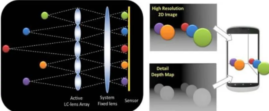
In this paper, we proposed a 3D image capturing system with high dynamic depth range (HDDR), which is inherited from the high dynamic range (HDR) method [5]. As show in Figure 1, the tunable LC lens array will be used in the HDDR capturing system. Each object in the field of view of camera will be clear captured by at least three elemental lenses. We can estimate the disparity of each object on three different elemental images, and calculate their depth as the lens array parameters are known. Finally, the depth information of each object will be fused into on refined depth map which named HDDR depth map.
Figure 1. An active LC lens array will be used in the HDDR system. Each object will be captured by at least three elemental lenses. The high resolution 2D image and detail 3D depth information will be recoded in different LC lens array modes.
d \
z
6
2. 3D DEPTH MAP GENERATED FROM DISPARITY
2.1 Depth map from disparity
Depth map from disparity is one method to estimate depth information with two or more images captured from different position. As shown in Figure 2, the object depth z has a geometrical relation with the object disparity Δx on two adjacent elemental images:
z =d
gΔx (1)
where d is the distance between the adjacent elemental lenses, and g is the gap from the lens array to the image sensor.
Figure 2. A tunable lens array placed in front of the camera, focusing on foreground, mid-ground, and background objects.
2.2 Depth Estimation Reference System (DERS)
In this paper, the depth maps were estimated from image disparity by Depth Estimation Reference System (DERS), released by Moving Picture Experts Group (MPEG). The disparity estimation in DERS mainly includes pixel matching, disparity computation using graph cuts optimization, and median filter; then perform gray level images to show different depth of objects (eight bits). The DERS is sensitive with image quality. Once an elemental image was defocused, there will be many mismatch of feature points and induce serious error in the depth map especially in a deep screen.
3. HIGH DYNAMIC DEPTH RANGE (HDDR) ALGORITHM
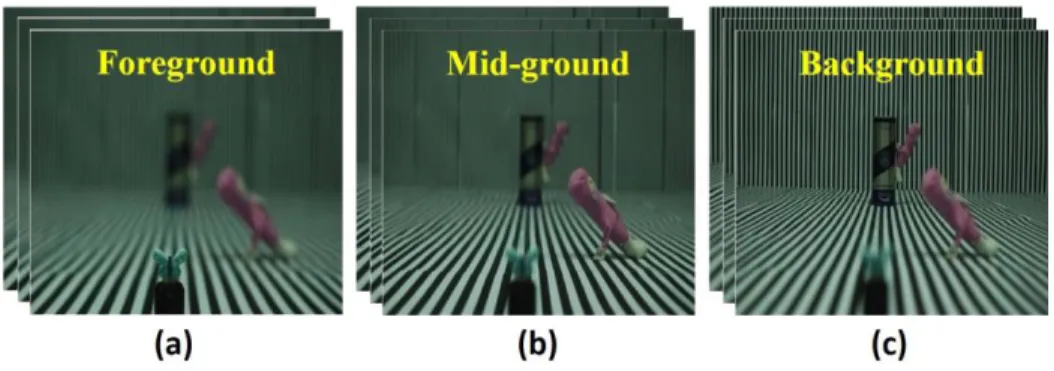
The high dynamic depth range (HDDR) capturing system is used for the deep scenes in which some objects were out of the depth of field of camera, so that the DERS could not generate correct depth map in these regions. In the HDDR capturing system, it needs N set of images focused on different depth region. Each set of images had left, center, and right view frames, which would provide image disparity for generating an elemental depth map. As shown in Figure 4, we captured the near, middle, background elemental image sets through a tunable lens array, in which the top three lenses focusing on the foreground objects, the second column lenses focusing on mid-ground objects, and the bottom column lenses focusing on the background. Therefore, we would have three set of images in each having their own all-in-focus region. In other words, any object in the field of view of camera was be clearly captured by at least three elemental lenses, which provide three different view-point images and disparity.
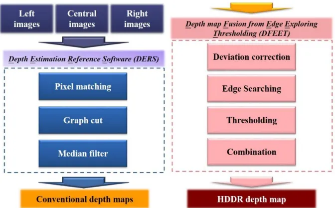
Figure 3 shows the HDDR algorithm process. Once we had three sets of left, center, and right view elemental images captured through the tunable lens array, we could input them into the DERS process and generate three elemental depth maps. In each elemental depth map, the depth information of objects in clearly captured region were correct, while those out-of-focus objects depth information had serious errors, as shown in Figure 7.
In the next process in Figure 3, we input these partial-correct elemental depth maps into DFEET, which would maintain the in-focused regions of each elemental depth map and fuse those regions together as an all-correct depth map called
Left
images
Central
images
Right
images
Depth Estimation Reference Software (DE
Pixel matching
Graph cut
Median filter
Conventional depth
maps]
+
Depth map Fusion from Edge Exploring
Thresholding (DFEET)
Deviation correction
Edge Searching
Thresholding
Combination
HDDR depth map
HDDR depth map. The object edges are regarded as the indication to judge the object was focused on or not. In this paper, we applied edge filter to analogize the region of depth of field. When it came to edge filter, high pass filter was the basis of edge detection. However, high pass filter such as Laplacian operator is sensitive to noise, so it requires noise suppression beforehand. Fortunately, Marr and Hildreth proposed Laplacian of Gaussian (LoG) method to take care of these two considerations. We created a mask by sampling the following equation:
△2 𝐺(𝑥, 𝑦) = (𝑥2+𝑦2−2𝜎2
𝜎4 ) 𝑒
−𝑥2+𝑦2
2𝜎2 (2)
where G(x,y) is a Gaussian function. As the name implies, we performed Gaussian smoothing as well as Laplacian sharpening. LoG is one of the common approaches used in edge detection and it was easy to implement with acceptable accuracy. Those areas in where the object edges can pass the Laplacian of Gaussian (LoG) filter will be maintained to HDDR depth map.
In the fusion step, once the representative focal point was discovered, we could find the corresponding gray level from the depth map. As a consequence, if N depth of field regions were arranged in capturing, N representative focal points would be extracted. By the same token, N-1 threshold gray value could be decided by averaging the corresponding gray levels of two adjacent representative focal points. According to the result from threshold, we fused those correct regions of depth maps into the HDDR depth map, as shown in Figure 8.
In the last step, combination, we had to deal with two problems which included voids and overlapping. As for overlapping, the relative large gray level was selected because it was on behalf of the front object point. However, the issue of voids was more difficult to handle because it was a process that makes something out of nothing. Thence, we had to rely on the side information of the voids. Lest smoothing operators would degrade the contrast between the object and its background, we used median filter to reconstruct the voids. Finally, two depth maps were cut out their wrong region by the threshold and then combined together.
Figure 3. The high dynamic depth range (HDDR) algorithm process. The images sets with left, central, and right views will be inputted into DERS and generated N sets of elemental depth maps. The DFEET step will fuse those elemental depth maps into a HDDR depth map.
Tunable Lens Arra
j1
Conventional came
Ti
Foreground Mid -ground Background
Figure 4. Capturing foreground, mid-ground, and background elemental images through a tunable lens array.
4. EXPERIMENTAL SETUP AND RESULTS
4.1 Tunable lens array imitation system
In this paper, a single camera was used to imitate the tunable lens array, as shown in Figure 5. By shifting the single camera in vertical and horizontal position, we captured 3 × 3 elemental images focusing on foreground, mid-ground, and background objects. The shift distance (as the elemental lens pitch) is 1cm, and the f-number of this single camera is f/2.8.
Figure 5. A single camera with f/2.8 is used to imitate the tunable lens array focusing on three different depth regions.
4.2 Elemental depth maps and HDDR depth map
In our experiment, three objects (a butterfly, a doll, and a can) were placed at three different depth (35 cm, 76cm, and 152 cm) shown in Figure 6. By the single camera imitation system we could capture three set of elemental images. Each elemental images has one in-focus object but two out-of-focus objects, because the depth of field of f/2.8 single camera was quite short, but our experiment scene was very deep. As shown in Figure 7, these image sets could generate three elemental depth maps with only partial-correct region by DERS.
With HDDR algorithm, these three elemental depth maps would be fused into a refined depth map shown in Figure 8(a). It shows that HDDR depth map maintained the correct regions from each elemental depth map, more details such as the doll’s arm and the butterfly wings were presented in the HDDR depth maps than in the depth map captured with large f-number camera.
11 1111111111111111111111111111111111111111 111 1111111 1 11111 .. I I I I I (a) (b) (c) (a) (b) (c) Focus on background
Focus on mid -ground
Focus on foreground
(a) (b)
Figure 6. The 3 × 3 elemental images focusing on foreground, mid-ground, background object captured by a moving camera.
Figure 7. Elemental depth maps generated from elemental image sets focusing on (a) background, (b) mid-ground, and (c) foreground objects. Each elemental depth map has one correct region, and two un-correct region.
4.3 Discussion
However, there were some voids and overlapping pixels in the combination area shown in Figure 9. As for overlapping, the relative large gray level was selected because it was on behalf of the front object point. However, the issue of voids was more difficult to handle because it was a process that makes something out of nothing. Thence, we had to rely on the side information of the voids. Lest smoothing operators would degrade the contrast between the object and its background. Finally, two depth maps were cut out their wrong region by the threshold and then combined together.
Figure 9. Details of HDDR fusion result from three step images.
5. CONCLUSION
We proposed a capturing system with high dynamic depth range (HDDR) to capture 3D image. By fusing a sequence of depth maps under different focal plane, we rendered the 3D capturing working range which is conventionally limited by the depth of field. In the future, following the concept of HDDR system, we will perform variable lens array with a sequential focal length. Each object in the working range would be clearly segmented on at least three elemental images it is supposed to extent the total depth of field of the capturing system in one shot. Therefore the depth map can be exactly estimated due to our fusion algorithm. Comparing to other depth map generation methods which need all-in-focus images, the HDDR system can not only capture real-time images but also estimate the near scene depth map without the limitation of narrow depth of field.
6. ACKNOWLEDGMENT
This work was financially supported by National Science Council, Taiwan, under contrasts NSC101-2221-E-009-120-MY3, and the polyimide was kindly supported by Chisso Corporation.
7. REFERENCE
[1] P. Kauff, N. Atzpadin, C. Fehn, M. Müller, O. Schreer, A. Smolic, "Depth map creation and image-based rendering for advanced 3DTV services providing interoperability and scalability," Signal Processing: Image Communication, 22, 217-234 (2007).
[2] R. Schulein, M. DaneshPanah, and B. Javidi, "3D imaging with axially distributed sensing," Optics letters 34, 2012-2014 (2009).
[3] R. Ng, M. Levoy, M. Brédif, G. Duval, M. Horowitz, and P. Hanrahan, "Light field photography with a hand-held plenoptic camera," Computer Science Technical Report CSTR 2, 2 (2005).
[4] C.-W. Chen, M. Cho, Y.-P. Huang, and B. Javidi, "Three-dimensional imaging with axially distributed sensing using electronically controlled liquid crystal lens," Optics Letters 37, 4125-4127 (2012).
[5] J. Kuang, H. Yamaguchi, C. Liu, G. M. Johnson, and M. D. Fairchild, "Evaluating HDR rendering algorithms," ACM Transactions on Applied Perception 4, 9 (2007).


![TraditionalMLCalgorithmsmainlytacklethebatchMLCproblem,wheretheinputdataarepresentedinabatch[24,28].Nevertheless,inmanyMLCapplicationssuchase-mailcategorization[22],multi-labelexamplesarriveasastream.Onlineanalysisistherefore dimensionreducermotivatedbyma](data:image/gif;base64,R0lGODlhAQABAIAAAP///wAAACH5BAEAAAAALAAAAAABAAEAAAICRAEAOw==)