Model to determine the self-resonant frequency of micromachined spiral inductors
C. C. Chen, Cheng-De Lin, and Y. T. Cheng
Citation: Applied Physics Letters 89, 103521 (2006); doi: 10.1063/1.2346371
View online: http://dx.doi.org/10.1063/1.2346371
View Table of Contents: http://scitation.aip.org/content/aip/journal/apl/89/10?ver=pdfcov Published by the AIP Publishing
Articles you may be interested in
On the frequency characteristic of inductor in the filter of Hall thrusters J. Vac. Sci. Technol. A 28, L9 (2010); 10.1116/1.3457152
Laser print patterning of planar spiral inductors and interdigitated capacitors J. Vac. Sci. Technol. B 27, 2745 (2009); 10.1116/1.3264673
High- Q micromachined three-dimensional integrated inductors for high-frequency applications J. Vac. Sci. Technol. B 25, 264 (2007); 10.1116/1.2433984
A novel primary inductor for a dual tuned resonant transformer Rev. Sci. Instrum. 72, 2438 (2001); 10.1063/1.1367354 Magnetic film inductors for radio frequency applications J. Appl. Phys. 82, 5247 (1997); 10.1063/1.366391
This article is copyrighted as indicated in the article. Reuse of AIP content is subject to the terms at: http://scitation.aip.org/termsconditions. Downloaded to IP: 140.113.38.11 On: Wed, 30 Apr 2014 08:33:17
Model to determine the self-resonant frequency of micromachined
spiral inductors
C. C. Chen, Cheng-De Lin, and Y. T. Chenga兲
Microsystems Integration Laboratory, Department of Electronics Engineering, National Chiao Tung University, Hsinchu, Taiwan 300, Republic of China
共Received 28 December 2005; accepted 24 July 2006; published online 7 September 2006兲 This letter presents an approach to characterize electron behaviors within polygonal micromachined spiral inductors in which self-resonance occurs. Combining with the concepts of anomalous dispersion, standing wave, and field scattering, the self-resonant frequency of the microinductors can be calculated by means of an associated analytical model. According to this model the self-resonant frequency 共SRF兲 can be derived as the “free electron” frequency of the inductor material. Simulation and measurement results validate that the model can provide a satisfactory prediction to the SRF of polygonal micromachined spiral inductors. © 2006 American Institute of
Physics. 关DOI:10.1063/1.2346371兴
Nowadays, several methodologies were proposed for predicting the self-resonant frequency共SRF兲 of a spiral in-ductor, such as empirical curve fitting using lumped circuit parameters,1–4data extraction from measured S parameters,5 electromagnetic field modeling,6 and method of moments 共MoM兲 analysis.7
Although these approaches precisely deter-mine the SRF, most of them are time consuming in calcula-tion and nonphysically straightforward which could not help circuit designer to easily reach for an optimal design. In or-der to surmount this predicament, an analytic closed-form model based on solid-state theory is presented for predicting the SRF of polygonal spiral microinductors.
Both conceptually and physically, the self-resonant oc-currence of a polygonal spiral microinductor indicates a complete stored energy transformation from magnetic energy into electrical energy, and vice versa. Being analogous with the anomalous dispersion of a conducting medium, it can be safely assumed that incident electromagnetic 共EM兲 waves will be entirely absorbed and transformed into the kinetic energy of free electrons inside the medium. In other words, the free electrons and associated EM energy can be treated as quantized waves and energy, respectively. Thus, the averaged kinetic energy of the free electrons inside the resonating in-ductor can be calculated using the dispersion relation8 as
EL=
冑
3 / 5共ប2/ me兲共32ne兲1/3k, where ប, ne, and me arePlanck’s constant, the free electron density, and electron mass in the inductor material, respectively. For copper, the free electron density and mass are 8.45⫻1028m−3 and
9.11⫻10−31kg, respectively. The factor k is the wave
num-ber of free electrons.
The wave number is a critical parameter which is closely related to the self-resonant frequency of polygonal spiral in-ductors. In this model, the concept of standing wave is implemented to characterize the free electron behavior while the inductor starts self-resonating. The free electrons similar to the notion of standing waves move back and forth through the terminals of the spiral inductor. Thus, the wave number k of the electron could be identified as m/ l where m and l represent an integral number and the total length of the spiral inductor, respectively. Once the free electrons behave like
standing waves, they can effectively absorb the energy of the EM wave propagating along the inductor. Meanwhile, since the operational frequency falls in a range of 1 – 20 GHz for most of radio frequency integrated circuits共RFICs兲 in which the EM wavelength is about centimeters long, the lowest mode would be the dominant one. In other words, the inte-gral number m is equal to unity and k =/ l. Thus, the self-resonant frequency of a spiral microinductor r would be
equal to the frequency of the resonating electron and could be calculated as follows: EL⬇
冑
3/5ប 2 me 共32ne兲1/3 l. 共1兲For the most part, the hypothesis simply embodies the cul-mination of the analytic model.
In addition, another hypothesis is made to facilitate a mental visualization of the electron behaviors inside the po-lygonal spiral inductor while EM wave propagates along with the entity. Homologizing the hydromechanics that ex-pounds the ideals about the fluidic flow through a channel with corners, it can be assumed that small free vortices would locally form in the apex of corner while electrons travel inside the polygonal spiral inductor. Since the vortex is a closed path and its diameter is much smaller than the in-ductor width, it is convenient to assume that the vortex is infinitesimal in this model. The electrons moving in a form of free vortex can be treated as a cluster of static electrons to build up a quasistatic electric field in the apex of the corner. Thus, according to Jackson’s field theory9and the notion of hydromechanics, there will be electric fields built up in the neighborhood of corners while an external electric field is applied on a conducting material. To a polygonal spiral in-ductor with several corners in the boundary, the quasistatic electric field built up in each corner has the following form which is calculated by the variation principle:10
E共r兲 = 1 40
q关+ 8 sin共2/4兲兴2
8h关csc共/2兲 − 1兴共+兲rˆ, 共2兲 where q is elementary charge, and h are the width and height of polygon spiral inductor, respectively, is the cor-ner angle, and the field is centered at the outer apex of each corner. By considering the field scattering, free electrons
a兲Electronic mail: [email protected]
APPLIED PHYSICS LETTERS 89, 103521共2006兲
0003-6951/2006/89共10兲/103521/3/$23.00 89, 103521-1 © 2006 American Institute of Physics This article is copyrighted as indicated in the article. Reuse of AIP content is subject to the terms at: http://scitation.aip.org/termsconditions. Downloaded to IP:
move near the corner would be scattered and alter their tra-jectories due to the built-up electrical field in the corner. The energy lost of free electrons due to the field scattering can be calculated as follows:11,12 EC=0h关csc共/2兲 − 1兴兩E兩q NV2/3
冑
eff csc2冉
− 2冊
= q 2 4NV2/3冑
eff 共+ 8 sin共2/4兲兲2 8共+兲 csc 2冉
− 2冊
for 0⬍⬍, 共3a兲 EC= lim N→⬁ q2 4NV2/3冑
eff 共+ 4冑
2兲2 4 2.7冕
dNfor =共circular spiral兲, 共3b兲
where N, V, andeffare the number of corners, the volume
of polygon spiral inductor, and the effective cross section of the inductor, respectively. Here, the effective cross sections are equal to 0.101, 0.281,13and 0.375 times the cross section of rectangular, octagonal, and circular inductors, respec-tively. The corresponding reference ground point for calcu-lating ECis assumed infinity. For the polygonal spiral
induc-tors in the RFIC design, the reference ground point would usually be far away from itself. Since the previous investi-gation already found that the substrate coupling effects could be neglected as long as the air gap is larger than 60m,14 which can be easily realized in the microinductor fabrication. Thus, it is reasonable and practical to be excused for this assumption.
After considering the energy lost in the corner field scat-tering, the realistic SRF,r, of a polygonal spiral inductor in
this model should be derived as follows which is equal to the free electron frequency:
r=共EL+ NEC兲/ប for 0 ⬍⬍, 共4a兲
r=共EL+ EC兲/ប for=. 共4b兲
Equation 共4兲 indicates that the electron starts resonating to form a standing wave as long as its energy is equal to the kinetic energy plus the total energy lost in the corner field scattering.
This integral model is examined by comparing with the contemporary three-dimensional finite element calculation via the ANSOFT-HFSS simulator15 whose accuracy is experi-mentally validated first. Figure 1 shows good S-parameter matches between the measurement result and high frequency structure simulator 共HFSS兲 simulation in a Smith chart for the case of two-port 3.5 turns rectangular micromachined spiral inductors关Fig. 1共a兲兴. The silicon substrate underneath the inductor has been removed. The detail fabrication and measurement of the spiral inductors have been reported in a previous publication.16 Although our measurement range is only up to 20 GHz due to the experimental limitation, Lee et
al. have shown that the HFSS can provide trustworthy results
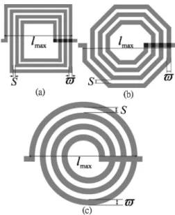
in the frequency prediction.17A variety of two-port polygo-nal spiral microinductors including rectangular, octagopolygo-nal, and circular inductors is utilized to verify the universality of the integral model as shown in Fig. 2. For a circular spiral inductor, its geometry is treated as infinite amount of minute corner sectors with the angle of that are serially linked together, so its self-resonant frequency can be determined by Eqs.共3b兲 and 共4b兲. In comparison with the self-resonant fre-quencies of the spiral inductors calculated by means of this model and theANSOFT-HFSS, less than 6% deviation has been found in Table I–III, respectively. The results indicate that a
TABLE I. Case A: Rectangular spiral inductor.
Comparisons
Number of turns共n兲
1.5 2.5 3.5 4.5 5.5 rfor HFSS共GHz兲 39.7 27.7 22.7 20.9 19.8 rfor model共GHz兲 38.6 28.6 23.9 21.4 19.9 FIG. 1. Comparisons between the HFSS simulation and measurement
re-sults of the 3.5 turns, 5m thick suspended spiral inductor共lmax= 300m, =15m, and S = 5m兲. The frequency range is from 1 to 20 GHz.
FIG. 2. Schematic diagram of the two ports spiral polygon inductor realiza-tions:共a兲 rectangular, 共b兲 octagonal, and 共c兲 circular. lmax, S, and are the maximum edge, line spacing, and linewidth of the polygon inductor, respectively.
103521-2 Chen, Lin, and Cheng Appl. Phys. Lett. 89, 103521共2006兲
This article is copyrighted as indicated in the article. Reuse of AIP content is subject to the terms at: http://scitation.aip.org/termsconditions. Downloaded to IP: 140.113.38.11 On: Wed, 30 Apr 2014 08:33:17
very close prediction can be realized using the integral model.
Moreover, the two different calculations have been com-pared in terms of the CPU processing time. The integral model is first programmed using MATLAB simulator.18 The comparison is then done in the same computer with the equipments of 3.4 GHz dual CPUs with DDR2 2048 Mbytes random access memories. About 6400 times of CPU time can be saved if the SRF is predicted using this integral model for a 5.5 turn octagonal spiral inductor. The model can in-deed provide a fast and accurate prediction. It is noted that the model can be also easily utilized to construct an equiva-lent lumped circuit model of spiral inductor for circuit de-signers while the inductance 共L兲 and the self-parasitic ca-pacitance共C兲 of inductor are derived by Greenhouse based approach19 and the SRF from our model.
Substrate coupling effect is excluded in this letter at this moment. The comparison is only based on the inductor with-out having substrate underneath. Although such a design has been proposed for high performance RFICs due to the high
Q characteristic of the inductor,20,21we think that the integral can be further modified for general on-chip inductors by con-sidering the interaction between the electric dipoles inside
the dielectric layer underneath the inductor and the free elec-trons inside the inductor.
In summary, the analysis creates a closed-form integral model which could well predict the SRF of a two-port po-lygonal micromachined spiral inductor. The model could provide not only a quick and accurate prediction but also a mathematically convenience for the optimal inductor design in physical sense.
This work was supported by the NSC 94-2220-E-009-002 project and in part by MediaTek research center and FY 95 ITRI/STC/JDRC at National Chiao Tung University.
1H. Lakdawala, X. Zhu, H. Luo, S. Santhanam, L. R. Carley, and G. K. Fedder, IEEE J. Solid-State Circuits 37, 394共2002兲.
2M. Grozing, A. Pascht, and M. Berroth, J. Spectrosc. Soc. Jpn. 50, 1927 共2001兲.
3B. Piernas, K. Nishikawa, K. Kamogawa, T. Nakagawa, and K. Araki, IEEE Trans. Microwave Theory Tech. 50, 4942共2002兲.
4H. Y. Tsui and J. Lau, IEEE Radio Frequency Integrated Circuits共RFIC兲 Symposium, 8-10 June 2003共IEEE, New York, 2003兲, p. 243.
5G.-A. Lee, M. Megahed, and F. De Flaviisl, J. Spectrosc. Soc. Jpn. 1, 527 共2003兲; 3, 1621 共2002兲.
6J. Sieiro, J. M. Lopez-Villegas, J. Cabanillas, J. A. Osorio, and J. Samitier, IEEE Radio Frequency Integrated Circuits 共RFIC兲 Symposium 共IEEE, New York, 2001兲, p. 121.
7J. C. Rautio, IEEE Trans. Microwave Theory Tech. 52, 257共2004兲. 8C. A. Brau, Modern Problems in Classical Electrodynamics共Oxford
Uni-versity Press, New York, 2004兲, Vol. 4, p. 240.
9J. D. Jackson, Classical Electrodynamics共Wiley, New York, 1998兲, Vol. 3, p. 104.
10G. B. Arfken and H. J. Weber, Mathematical Methods for Physicists 共Aca-demic, San Diego, 2001兲, Vol. 17, p. 1017
11A. S. Kronfeld and B. Nižić, Phys. Rev. D 44, 3445共1991兲.
12F. J. Federspiel, R. A. Eisenstein, M. A. Lucas, B. E. MacGibbon, K. Mellondorf, A. M. Nathan, A. O’Neill, and D. P. Wells, Phys. Rev. Lett.
67, 1511共1991兲.
13C. C. Chen, J. K. Huang, and Y. T. Cheng, IEEE Microw. Wirel. Compon. Lett. 15, 778共2005兲.
14J. Y. Park and M. G. Allen, IEEE Trans. Adv. Packag. 22, 207共1999兲. 15Ansoft,
ANSOFT-HFSS, Version 9.0, http://www.ansoft.com/products/hf 16J. W. Lin, C. C. Chen, and Y.-T. Cheng, IEEE Trans. Electron Devices 52,
1489共2005兲.
17G.-A. Lee, M. Megahed, and F. De Flaviis, IEEE MTT-S Int. Microwave Symp. Dig. 3, 1621共2002兲.
18Mathwork,
MATLAB, Version 7.0.4, http://www.mathworks.com/products/ matlab/
19S. Jenei, B. K. J. C. Nauwelaers, and S. Decoutere, IEEE J. Solid-State Circuits 37, 77共2002兲.
20H. Lakdawala, X. Zhu, X. H. Luo, S. Santhanam, L. R. Carley, and G. K. Fedder, IEEE J. Solid-State Circuits 37, 394共2002兲.
21J. Hongrui, Y. Wang, J.-L. A. Yeh, and N. C. Tien, J. Spectrosc. Soc. Jpn.
48, 2415共2000兲.
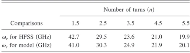
TABLE II. Case B: Octagonal spiral inductor.
Comparisons
Number of turns共n兲
1.5 2.5 3.5 4.5 5.5 rfor HFSS共GHz兲 42.7 29.5 23.6 21.0 19.9 rfor model共GHz兲 41.0 30.3 24.9 21.9 20.1
TABLE III. Case C: Circular spiral inductor. Around 62000 tetrahedral meshes with an average size of 0.15m are utilized for the HFSS analyses. The analysis error is controlled below 0.005%. The mesh number will be slightly different in each case due to the geometrical difference. lmax = 300m,=15m, and S = 5m. Comparisons Number of turns共n兲 1.5 2.5 3.5 4.5 5.5 rfor HFSS共GHz兲 43.3 30.5 24.6 21.9 20.7 rfor model共GHz兲 41.0 30.6 25.8 23.2 21.7
103521-3 Chen, Lin, and Cheng Appl. Phys. Lett. 89, 103521共2006兲
This article is copyrighted as indicated in the article. Reuse of AIP content is subject to the terms at: http://scitation.aip.org/termsconditions. Downloaded to IP: 140.113.38.11 On: Wed, 30 Apr 2014 08:33:17