國
立
交
通
大
學
網路工程研究所
碩
士
論
文
一個在 IEEE 802.16j 行動式中繼站模式上
基於網路的快速行動交遞機制
A Network-based Fast Handover design over IEEE 802.16j
Mobile RS mode
研 究 生:姚祺昉
指導教授:陳耀宗 教授
一個在 IEEE 802.16j 行動式中繼站模式上
基於網路的快速行動交遞機制
A Network-based Fast Handover Scheme over IEEE 802.16j Mobile RS
Mode
研 究 生:姚祺昉 Student:Chi-Fang Yao
指導教授:陳耀宗 Advisor:Yaw-Chung Chen
國 立 交 通 大 學
網 路 工 程 研 究 所
碩 士 論 文
A ThesisSubmitted to Institute of Network Engineering College of Computer Science
National Chiao Tung University in partial Fulfillment of the Requirements
for the Degree of Master
In
Computer Science
July 2011
Hsinchu, Taiwan, Republic of China
i
一個在 IEEE 802.16j 行動式中繼站模式上
基於網路的快速行動交遞機制
學生:姚祺昉 指導教授:陳耀宗 教授
國立交通大學網路工程研究所
摘要
近年來無線網路之技術快速的發展,其中之一便是 IEEE 802.16 (WiMAX)。在此類 無線寬頻系統如此迅速的發展之下,如何在行動 all-IP 網路服務中達成無接縫的交 遞(基地台交換)顯得非常重要。現今的網路 IP 層交遞機制可分為兩種範疇,其一為 基於行動裝置的機制,例如 Mobile IPv6 (MIPv6);其二為基於網路的機制,例如 Proxy Mobile IPv6 (PMIPv6)。其中 PMIPv6 擁有較 MIPv6 更優良的表現,並很有希望是下一 世代行動 all-IP 網路服務的選擇。然而,在 IEEE 802.16j 行動式中繼站模式之上, PMIPv6 並無法避免封包遺失以及較長的服務中斷時間。因此在這篇論文中,我們 提出了一個在 IEEE 802.16j 行動式中繼站模式之上,基於網路的、並且跨網路分層 的行動交遞機制。由於使用新提出的控制訊息還有通道路由器的緩衝暫存功能,所 提出的機制可以讓資料聯結層與網路 IP 層的交遞同時進行,並且避免封包的遺失。 最後,數學分析與模擬的結果顯示出本機制在效能表現上有顯著的提升。ii
A Network-based Fast Handover Scheme over IEEE 802.16j Mobile RS Mode
Student:Chi-Fang Yao Advisor:Prof. Yaw-Chung Chen
Institute of Network Engineering
National Chiao Tung University
Abstract
Wireless technology, such as IEEE 802.16 (WiMAX), advances quickly in recent years. With the rapid development of broadband wireless access system, how to achieve seamless handover is essential to the all-IP mobile services. Nowadays IP layer handover schemes can be classified into two categories, the host based approach such as Mobile IPv6 (MIPv6), and the network-based approach such as Proxy Mobile IPv6 (PMIPv6). PMIPv6 outperforms MIPv6 and is a promising option for next-generation all-IP mobile networks. However, PMIPv6 may not prevent packet loss and long service disruption time (SDT) problems in IEEE 802.16j mobile relay station (MRS) mode. In this thesis, a network-based cross-layering handover mechanism was proposed for IEEE 802.16j MRS mode. With the newly introduced control message and buffering mechanism in Access Router, the Data-Link layer and IP layer handover are processed concurrently and packet loss is prevented. Finally, both numerical analysis and simulation results show remarkable improvement of performance.
iii
誌謝
隨著這篇論文的完成,我的學生生涯也接近尾聲。在交通大學資訊工程學系大 學部四年、網路工程研究所碩士班兩年,交大給予我的專業訓練濃縮成精華展現於 這篇論文中。這六年來,有歡笑、有淚水,有失落、有得著,點點滴滴的往事也隨 著這篇論文幻化成回憶,當然,更有說不盡的感謝。 首先,我要感謝交通大學,在人文薈萃的新竹給予了我如此資源豐富的學習環 境,師長同學們凝聚出來的濃厚學習風氣,讓我-一個懵懂小子得以一窺科學研究 的博大精深。其中最重要的當然是我的指導教授-陳耀宗教授,他的諄諄教誨讓我 能一步步找到研究方向與方法,他所帶領的多媒體通訊實驗室也成為了我學習研究 的最佳環境。這兩年來陳教授的悉心指導不但讓我能完成這篇論文,相信也對我未 來的工作能力提供了最好的訓練,在此我要說聲:"教授,您辛苦了,衷心感謝您 "。 接下來我要感謝本多媒體通訊實驗室裡最尊敬也最優秀的學長姐們,博班的施 振華學長、林冠宇學長、郭俊利學長、許育嘉學長,碩班的林振全學長、黃紀寰學 長、周吟珊學姐、章瑋芸學姐、簡嘉瑋學長,你們在研究領域中的卓越表現與指導 永遠是我的楷模。尤其是施振華學長對本論文的直接指導,您不厭其煩的提點讓我 沒齒難忘。還有同學們王銘慶、陳閔煌、王博謙,我們互相扶持砥礪,切磋學業, 是我學生生涯中充實進步的時刻。雖然只有短短兩年的緣份相處,相信我們都能是 一輩子的好朋友、好夥伴。 最後我要感謝我的父母親與家人,伴我走過人生的高低起伏,永遠在溫暖的家 裡提供我支持與勉勵。另外還要感謝我的好朋友們,有你們的陪伴相處,研究生活 從來不孤單寂寞,而是多采多姿。至於其他的,要感謝的太多了,就感謝上帝吧! 姚祺昉 僅誌於交通大學網路工程研究所 中華民國一OO年八月iv
Contents
摘要 ... i Abstract ...ii Contents ... iv Table list ... viFigure List ...vii
Chapter 1 Introduction... 1
1.1 IEEE 802.16e and 802.16j standards ... 1
1.2 Mobile IPv6 and Proxy Mobile IPv6 ... 3
1.3 Motivation and purpose ... 7
Chapter 2 Related Work ... 9
2.1 IEEE802.16j MRS Handover ... 9
2.2 Handover procedures with MRS in Mobile IPv6 ... 11
2.3 Handover procedures with MRS in Proxy Mobile IPv6 ... 12
Chapter 3 Proposed Scheme ... 14
3.1 Network scenario ... 14
3.2 Definition of proposed messages ... 15
3.2.1 Proposed messages in WiMAX network ... 15
3.2.2 Proposed messages in wired network ... 17
3.2.3 Modified Proxy Binding Update and Proxy Binding Acknowledgement ... 19
3.3 Proposed handover procedures ... 22
3.3.1 Predictive mode ... 22
3.3.2 Reactive mode ... 24
Chapter 4 Numerical Analysis ... 27
v
4.2 Numerical Analysis Results ... 30
Chapter 5 Simulation and Results ... 34
5.1 Simulation environment ... 34
5.2 Simulation results ... 36
Chapter 6 Conclusions... 41
vi
Table list
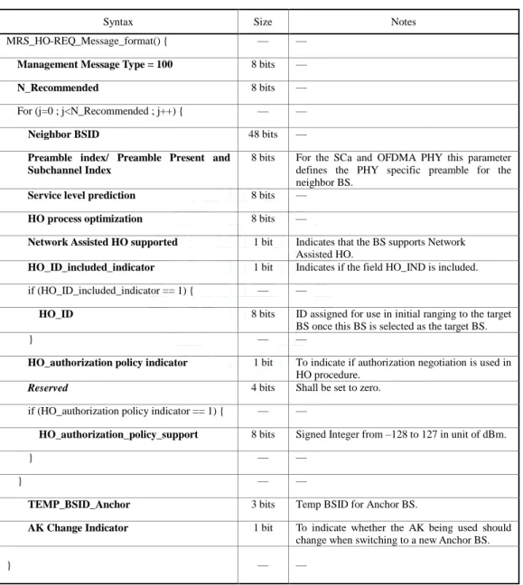
Table 3.1 MRS_HO-REQ message format ... 16
Table 3.2 MRS_HO-RSP message format ... 17
Table 3.3 MRS_HO-CLT message format ... 17
Table 3.4 HO-REQ message format ... 18
Table 3.5 HO-RSP message format ... 18
Table 3.6 HO-CLT format ... 19
Table 3.7 Modified PBU message format ... 20
Table 3.8 Mobility options for modified PBU message format ... 20
Table 3.9 Modified PBA message format ... 21
Table 3.10 Mobility options for modified PBA message format ... 21
Table 4.1 Parameters for calculation ... 28
Table 5.1 Simulation parameters ... 35
vii
Figure List
Figure 1.1 Three types of relay stations ... 3
Figure 1.2 Overview of Mobile IP ... 4
Figure 1.3 Overview of PMIPv6 ... 7
Figure 2.1 MRS layer 2 handover procedure ... 9
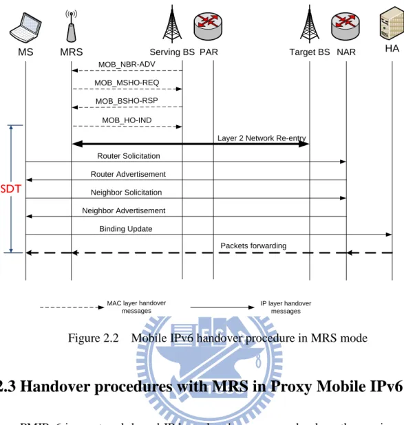
Figure 2.2 Mobile IPv6 handover procedure in MRS mode ... 12
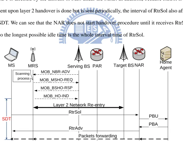
Figure 2.3 Proxy Mobile IPv6 handover procedure in MRS mode ... 13
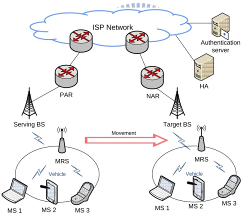
Figure 3.1 Vehicular network scenario ... 14
Figure 3.2 Predictive mode of proposed scheme ... 23
Figure 3.3 Reactive mode of proposed scheme ... 25
Figure 4.1 Impact of AR-HA delay on SDT ... 31
Figure 4.2 Impact of AR-HA delay on #lost packets ... 32
Figure 4.3 Overlap between two BSs ... 33
Figure 4.4 Impact of Tscan on the proposed scheme ... 33
Figure 5.1 Network topology for simulation. ... 35
Figure 5.2 Packet sequence number to receiving time in MIPv6 scheme ... 37
Figure 5.3 Packet sequence number to receiving time in PMIPv6 (t=0) scheme ... 37
Figure 5.4 Packet sequence number to receiving time in PMIPv6 (t=2) scheme ... 37
Figure 5.5 Packet sequence number to receiving time in PMIPv6 (t=4) scheme ... 38
Figure 5.6 Packet sequence number to receiving time in proposed scheme (predictive mode) ... 38
Figure 5.7 Packet sequence number to receiving time in proposed scheme (reactive mode) ... 38
1
Chapter 1 Introduction
Broadband Wireless Metropolitan Area networks, such as the IEEE 802.16 standards (Worldwide Interoperability for Microwave Access, WiMAX) [1], are developing very rapidly in recent years. The standards aim to provide low-cost, high bandwidth and scalable solution for multimedia services from backbone networks to wireless users. Moreover, it has potential to provide portable mobile broadband connectivity across cities and country sides through a variety of devices. In order to support connectivity in such large area, portability and mobility have become major issues in IEEE 802.16. And when it comes to mobility, the process of handover plays an important role to provide continuous service.
1.1 IEEE 802.16e and 802.16j standards
IEEE 802.16e is a significant milestone in the developing history of WiMAX. In PHY (physical layer), the IEEE 802.16e uses scalable Orthogonal Frequency Division Multiplexing (OFDMA) to carry data supporting bandwidth between 1.25MHz and 20MHz. Other features include using Adaptive Antenna System (AAS), Multiple Input Multiple Output (MIMO), Multicast and Broadcast service (MBS), and allocating specific Quality of service (QoS) class to each connection. In addition, terminal is allowed to move while receiving wireless traffic and so that the terminals can maintain the same IP sessions during Data-link layer handover. Therefore the IEEE 802.16e, which is published in December 2005, is the first one to add mobility support to the original WiMAX standard [2].
2
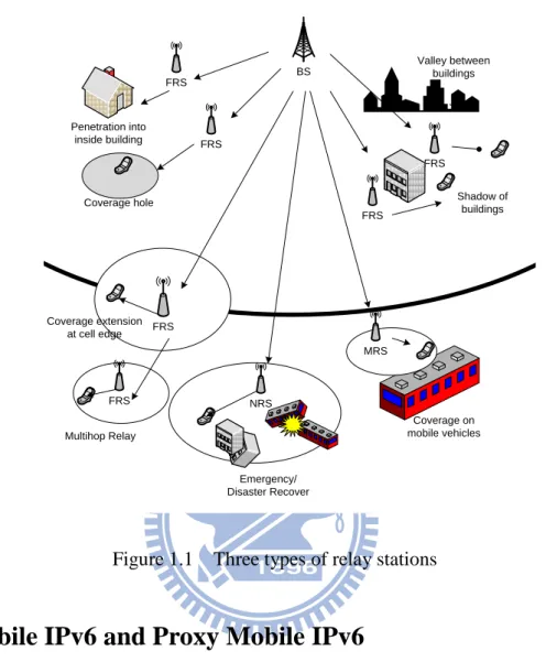
One of the main features of 802.16j is multi-hop relay which is added into the network structure to enhance the function of 802.16e. By deploying the new equipment, which is called Relay Station (RS), the coverage of Base Station (BS) can be extended and capacity of a specific area can be increased. And at the same time, there is no need to modify the end user equipment in 802.16e [4][5]. The new standard solved some problems in the older one, for example: the limitation of BSs deployment, high cost of backbone networks, and lack of network infrastructure in newly developed area.
There are two main types of RS: fixed and mobile (FRS and MRS). The FRS is permanently installed at the same place whereas the MRS is usually implemented into moving vehicles, such as bus, train, etc. The main functions of FRS provide additional capacity to areas and extend coverage at cell edge, indoor users, and coverage holes in which the signal from BS is blocked by buildings. Also, the FRS can provide access for clusters of users outside the BS’s coverage area, without directly construct a new BS for those users. On the other hand, the MRS provides its functions in two modes, the moving BS mode and the moving RS mode.
In moving BS mode, the MRS behaves like a small BS with the IP layer functionality and thus it can assign IP addresses and connection identifiers (CID) to end terminals connected to it. However, the MRS should be modified and cost more hardware enhancement in moving BS mode because it must provide both layer 2 and IP layer handover functions. As a matter of fact, the IEEE 802.16j would basically perform the other mode described below. In moving RS mode, when the MRS is placed on a vehicle, it is connected to BS via mobile link, and it provides a coverage area for all end terminals riding on the vehicle as a fixed access link. In addition to the main two types of RS, there are another one called Nomadic RS (NRS), which work as a temporary RS to extent coverage and capacity in areas which need emergency signal enhancement [6]. Different
3
kinds of RS and their functions are shown in Figure 1.1.
BS FRS FRS FRS FRS FRS FRS MRS NRS Coverage extension at cell edge Penetration into inside building Coverage hole Valley between buildings Shadow of buildings Multihop Relay Emergency/ Disaster Recover Coverage on mobile vehicles
Figure 1.1 Three types of relay stations
1.2 Mobile IPv6 and Proxy Mobile IPv6
Mobile IP (MIP) is a standard published by Internet Engineering Task Force (IETF) [7] which defines a communication protocol that allow a mobile node (MN, or Mobile Station, MS) to retain its home address on moving from network to another. While MS uses MIP moving between networks, there is no need to modify the intermediate routing nodes.
In MIP, each MS has two network addresses – the permanent home address (HoA) and the Care-of-Address (CoA), which is calculated and reassigned while MS travels to another network. In MS’s home network, the Home Agent (HA) is responsible for keeping the information about MS’s permanent address. The HA also keeps being aware of which MNs are under the home network, and which MNs are visiting a foreign network.
4
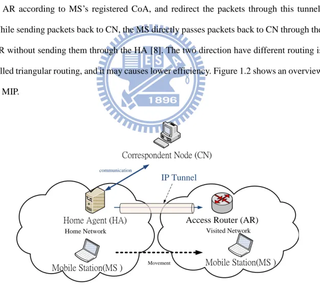
Normally when MS is under the home network, a node wanting to communicate with the MS, which is called Correspondent Node (CN), uses the permanent address of MS as the destination address in IP datagram to send packets to the MS. When MS travels to a foreign network, it tries to connect to internet through the local router, which is called access router (AR), and generally AR also works as Foreign Agent (FA). The AR advertises the address every time an MS moves into its network. And then the AR would assign a newly calculated CoA to MS. And afterwards, the MS would register this CoA information to the MS’s HA and CN. Now the packets from CN to MS are still routed by standard IP routing mechanisms, so the packets are forwarded to the HA. The HA would establish an IP tunnel to AR according to MS’s registered CoA, and redirect the packets through this tunnel. While sending packets back to CN, the MS directly passes packets back to CN through the AR without sending them through the HA [8]. The two direction have different routing is called triangular routing, and it may causes lower efficiency. Figure 1.2 shows an overview of MIP.
Mobile Station(MS ) Home Agent (HA)
Correspondent Node (CN)
Access Router (AR)
Home Network Visited Network
Mobile Station(MS ) Movement
IP Tunnel
communication
5
Mobile IPv6 (MIPv6) is an enhancement of Mobile IPv4 and is developed to improve mobile communications in some circumstances. MIPv6 uses various methods to solve many problems in MIPv4, for example, the triangular routing, weaker security, and the limitation of address space [9]. There are some optimization steps which are triggered by the MS to improve the routing efficiency. In the route optimization process, after the MS switches to AR’s subnet, it registers this binding to the CN. By finishing this process, the CN can directly send packets to MS, instead of sending packets through HA continuously [10].
Although MIPv6 provide better solution than MIPv4, there still remain some problems, such as packet loss, handover latency, and signaling overhead. Furthermore, handover latency would seriously affect QoS but MIP does not offer any guarantee to it. As a result, another standard mentioned in following paragraph is developed to improve the performance of MIPv6.
Proxy Mobile IPv6 (PMIPv6, or PMIP) is designed as a network-based IP mobility management protocol and is also published by IETF. Just as MIP, PMIPv6 has the same mobile functions and there is no need to modify the host’s TCP/IP protocol stack. The main difference between them is that with PMIPv6, the MS can travel to another point-of-attachment (PoA) to the internet without MS participated in any mobility-related signaling. Unlike the MIP, the function that allows the MS to maintain the same IP address in different networks is implemented by the network but not triggered by MS. Therefore it is not necessary to modify MS’s mobility functions (It seems like remain in the same network on MS’s point of view) [11]. Other benefits of PMIPv6 include supporting both IPv4/IPv6, making better use of wireless resources, and improving handover performance [12].
6
management – Local Mobility Anchor (LMA) and the Mobile Access Gateway (MAG). The LMA is similar to HA in MIP, and it maintains the MS’s address is reachable while MS moves around within a PMIPv6 domain. The LMA also includes a binding cache entry for each currently registered MS, which stores more information than those in MIPv6’s HA. The additional information includes MS-Identifier, the MS’s home network prefix, a flag indicating a proxy registration, and the interface identifier of the bi-directional tunnel between the LMA and MAG. On the other hand, the MAG which usually runs on an AR, detects the movement of MNs and takes charge of managing mobility related signaling for MNs attached to MAG’s access link. In this thesis, when it comes to PMIPv6, we use the term AR to represent the MAG, and HA to represent LMA, so that we can unify the equipments’ names in different protocols.
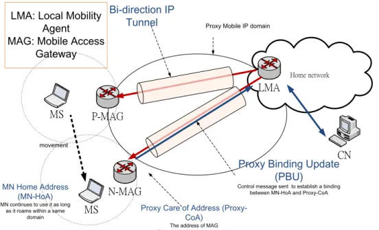
The following is how PMIPv6 works (Figure 1.3). When a MS attaches to certain MAG, the MAG first performs the authentication procedure and obtains the profile of the MS. Then the MAG sends a proxy binding update (PBU) message include the MS-Identifier to the MS’s LMA on behalf of the MS. Once the LMA receives the PBU message, it allocates an appropriate home network prefix for the MS and encapsulates this prefix into proxy binding acknowledgment (PBA) message, and sends PBA back to MAG. Now the LMA and MAG have enough information and create a bi-directional tunnel for enabling the MS to use an address from its home network prefix and the MAG emulates the MS’s home network on the access network for the MS. After the bi-directional tunnel is successfully established, all traffic sent by the MS would be routed to its LMA through the tunnel. And packets from CN to MS would send to the LMA in advance, and then the LMA forwards them to the MAG through the tunnel. Finally, the MAG removes the outer header of the packets and forwards them to the MS.
7 Home network LMA MS N-MAG P-MAG MS Bi-direction IP
Tunnel Proxy Mobile IP domain
LMA: Local Mobility Agent
MAG: Mobile Access Gateway
Proxy Binding Update (PBU)
Control message sent to establish a binding between MN-HoA and Proxy-CoA MN Home Address
(MN-HoA) MN continues to use it as long
as it roams within a same domain
movement
Proxy Care of Address (Proxy-CoA)
The address of MAG That will be the tunnel end-point
CN
Figure 1.3 Overview of PMIPv6.
1.3 Motivation and purpose
From the above description, we can see that IEEE 802.16j is one of the latest WiMAX standards, which provides good coverage extension with low cost. In this standard, the MRS with moving RS mode is an efficient method to provide internet access for passengers aboard. IEEE 802.16j defined the handover procedures in Data-Link layer (MAC layer, or layer 2); however, when IEEE 802.16j combines the mobile mechanisms in network layer (IP layer, or layer 3) there are still some problems to be solved, including packet loss and long service disruption time (SDT). In many real time applications such as video streaming and VoIP (Voice over IP), these problems may seriously affect the performance and user’s experience. As a result, achieving seamless handover in IEEE 802.16j with MRS mode has become the main purpose of this thesis.
The two main IP layer handover schemes mentioned above can be classified into two categories. One, MIPv6 belongs to the host based approach, which requires modification to the protocol stack of the mobile node MS. And the other one, PMIPv6 belongs to the
8
network-based approach, in which the serving network controls IP mobility management on behalf of the MS. Although PMIPv6 outperforms MIPv6 in the aspects of deployment, performance, and management of network service provider [13], problems of packet loss and long SDT still occurs. Thus, several works [14] [15] proposed the cross-layer based scheme to improve SDT and packet loss. However, enhanced schemes for PMIPv6 can’t be applied in IEEE 802.16j MRS mode because the layer 2 handover procedures in MRS mode are different from common situation. In common situation, MS performs layer 2 handover procedures whereas MRS performs layer 2 handover procedures in MRS mode since the MNs under the MRS still attach to it when MRS migrates from one BS to another one. The enhanced schemes for PMIPv6 assume that the layer 2 and IP layer handover are performed by MS and new access router (NAR), respectively, and then lead layer 2 in MS and IP layer in NAR to cooperate and result in reduced SDT. Hence these schemes can’t be applied and only the MIPv6 or PMIPv6 schemes can be used in MRS mode.
In this thesis, in order to achieve seamless mobility for MS in IEEE 802.16j MRS mode, we proposed a network-based cross-layering handover scheme to solve the packet loss problem and to reduce the SDT. There are several new control messages proposed and defined in chapter 3, and by exchanging these messages, the layer 2 handover in MRS can cooperate with the IP layer handover in NAR. The rest of this thesis is organized as follows. In chapter 2, the layer 2 handover procedure of IEEE 802.16j, and the handover procedures of MIPv6/PMIPv6 with IEEE802.16j are described. In chapter 3, the definition of new messages and the proposed handover procedure are described. In chapter 4, we analyze the proposed scheme. Then in chapter 5, the simulation results show how much progress in packet loss and reduced SDT by our method. Finally chapter 6 concludes this thesis.
9
Chapter 2 Related Work
In this chapter, the Data-link layer (layer 2) handover procedures defined in IEEE 802.16j standard will be described first. And then we will present the handover procedures in Mobile IPv6 and Proxy Mobile IPv6, and show how the two IP layer mobile mechanisms cooperate with IEEE 802.16j.
2.1 IEEE802.16j MRS Handover
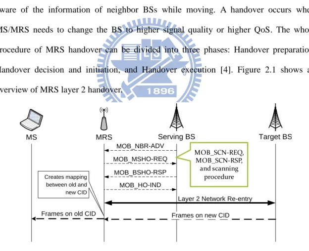
IEEE 802.16j defines the MS handover process in layer 2. The MS/MRS keeps aware of the information of neighbor BSs while moving. A handover occurs when MS/MRS needs to change the BS to higher signal quality or higher QoS. The whole procedure of MRS handover can be divided into three phases: Handover preparation, Handover decision and initiation, and Handover execution [4]. Figure 2.1 shows an overview of MRS layer 2 handover.
MS MRS Serving BS Target BS
MOB_NBR-ADV MOB_MSHO-REQ MOB_BSHO-RSP
MOB_HO-IND
Layer 2 Network Re-entry Frames on new CID Frames on old CID
Creates mapping between old and new CID
MOB_SCN-REQ, MOB_SCN-RSP,
and scanning procedure
Figure 2.1 MRS layer 2 handover procedure
First, the handover preparation phase takes place. Three procedures are included - network topology advertisement, scanning, and association procedure. During network
10
topology advertisement procedure, a BS periodically broadcasts MOB_NBR-ADV (Mobile Neighbor Advertisement) which contains information about the network topology MAC management message. This message tells the MRS the information about the network identification, provides information about neighboring BSs, and facilitates MRS synchronization with neighboring BSs. After obtaining information from this message, the MRS can make an immediate decision for a future handover. In the scanning procedure, MOB_SCN-REQ (Mobile Scanning Interval Allocation Request) and MOB_SCN-RSP (Mobile Scanning Interval Allocation Response) messages are exchanged. Through these two messages the MRS and the BSs it wants to scan can coordinate for the scanning. The MRS scans the neighboring BSs to seek and monitor one that is suitable for a handover candidate. The last one – the association procedure is an optional ranging procedure occurring during the scanning interval with respect to one of the neighbor BSs.
Secondly in handover decision and initiation phase, the MRS selects one or more candidate BSs. The MRS may make a decision to initiate the handover and sends a MOB_MSHO-REQ (Mobile MS Handover Request) message to current serving BS. Before replying MOB_BSHO-RSP message with recommended target BSs to the MRS, the serving BS may send the MAC addresses and CIDs of the MSs under MRS to neighbor BSs over the backbone. The handover can also initiated by the serving BS which would send MOB_BSHO-REQ (Mobile BS Handover Request) message to the MRS.
The last phase is handover execution. The MRS chooses a target BSand then sends
MOB_HO-IND (Mobile Handover Indication) message to indicate a handover to the serving BS. After this message, the serving BS officially terminates the connection to MRS so that no packet would be delivered by serving BS. And then the MRS switches to
11
target link and performs downlink synchronization, raging, and network re-entry to the target BS. Next, the target BS sends RNG-RSP (ranging response) message to MRS to assign new CIDs for MSs, then MRS creates mapping between old and new CIDs for each MS. Once the handover execution is done, the target BS, which has become the serving BS, can start forwarding packets to the MRS and provide services.
2.2 Handover procedures with MRS in Mobile IPv6
In this section we will describe how MIPv6 works with IEEE 802.16j MRS mode. While MRS enters a different subnet, the MSs connected to it must re-configure a CoA address, new IP address, and re-establish its IP connection based on the new IP address. However, MSs cannot realize that they are under another network in the first place until they receive the router advertisement (RtrAdv) message periodically sent by the NAR. The MS can also request the NAR to send router advertisement by sending router solicitation (RtrSol) message. Next, the MS uses information exchanged in these messages to create a new CoA and confirms this CoA by sending neighbor solicitation message. After the CoA confirmation is done by the NAR (the confirmation is called duplicate address detection, DAD), the MS sends a binding update message to its HA, which updates the binding cache upon receiving this message [9].
To sum up the procedure in MIPv6, after finishing the layer 2 handover of MRS, the MS performs the IP layer handover procedures including movement detection, new care of address (CoA) configuration and DAD. And binding update is sent by the MS to officially start connection to the NAR. We can see that the two layer handover mechanism operate sequentially, therefore this handover procedures lead to a long SDT and packet loss. Figure 2.2 shows the detail handover procedure using MIPv6.
12
MS MRS Serving BS PAR Target BS NAR
MOB_NBR-ADV Router Solicitation Router Advertisement MOB_MSHO-REQ MOB_BSHO-RSP MOB_HO-IND
Layer 2 Network Re-entry
Packets forwarding HA Neighbor Solicitation Neighbor Advertisement Binding Update SDT
MAC layer handover messages
IP layer handover messages
Figure 2.2 Mobile IPv6 handover procedure in MRS mode
2.3 Handover procedures with MRS in Proxy Mobile IPv6
PMIPv6 is a network-based IP layer handover approach where the serving network controls IP mobility management on behalf of the MS. Hence, when PMIPv6 is used over IEEE 802.16j network, the IP layer mobility management is done by the AR so the MS never knows about the subnet changing and the occurrence of IP layer handover. The new AR (NAR) will start to perform the IP layer handover procedures on behalf of the MS via PMIPv6 after it receives the RtrSol (Router Solicitation) periodically sent by MS, which may arrive at any time after the MRS's attachment. Note that we use the term ―HA‖ and ―NAR‖ instead of ―LMA‖ and ―MAG‖ for the reason of consistency..
Figure 2.3 shows the PMIPv6 procedure [11]. After NAR detects the new MS is under its subnet by RtrSol message, it sends a PBU (Proxy Binding Update) to the MS’s home
13
HA. The HA obtain the MS’s identifier form PBU and then allocates an appropriate home network prefix for the MS. Afterwards, the prefix is encapsulate in PBA (Proxy Binding Acknowledgement) message and sent back to NAR. At the same time the bi-directional tunnel is created between HA and NAR. Now the NAR sends RtrAdv (Router advertisement) message to the MS as a response of prior RtrSol message, and start forwarding data packets tunneled from HA. In PMIPv6 scheme, the packets forwarding from the PAR is not allowed since MOB_HO-IND message is exchanged, so the packet loss may occur during the periods of the layer 2 network re-entry (L2 RN) of MRS and the following PMIPv6 handover procedures. Since the IP layer handover of MSs are done one by one in this scheme, the SDT is affected by the amount of MSs under the MRS. In addition, because RtrSol is not sent upon layer 2 handover is done but is sent periodically, the interval of RtrSol also affect SDT. We can see that the NAR does not start handover procedure until it receives RtrSol, so the longest possible idle time is the whole interval time of RtrSol.
MS MRS Serving BS PAR Target BS NAR MOB_NBR-ADV
MOB_MSHO-REQ MOB_BSHO-RSP
MOB_HO-IND
Layer 2 Network Re-entry
Packets forwarding Home Agent SDT RtrSol RtrAdv PBU PBA Scanning process
14
Chapter 3 Proposed Scheme
3.1 Network scenario
In this thesis we proposed a cross-layer handover mechanism over IEEE 802.16j network, and the detail network scenario will be described below. The typical deployment of IEEE 802.16j is to let a MRS mounted on a public transportation vehicle, such as a bus or a train. The passengers’ mobile devices, like a notebook or a cell phone, link to the BS through MRS instead of direct link to the BS. The MRS and MSs travel together as long as the passengers are on board.
Vehicle Vehicle ISP Network Serving BS MRS Target BS MRS MS 1 MS 1 Movement HA Authentication server PAR NAR MS 2 MS 3 MS 2 MS 3
Figure 3.1 Vehicular network scenario.
In this scenario, the MRS works in mobile RS (MRS) mode and support link access for MSs. When the MRS switches from the serving BS to target BS belonging to a different subnet, the MSs attached to it should involve IP layer handover. The MRS itself
15
performs layer 2 handover to the target BS, at the same time it continuously provide fixed access link for MSs. As a result, the MSs attached to the MRS retain connections and do not have to perform a layer 2 handover. In MIP and PMIPv6 mentioned in Section 2.2 and 2.3, the MS or NAR conducts IP layer handover after the MRS finished the layer 2 handover.
Our proposed handover procedure is based on PMIPv6, but after the MOB_BSHO_RSP message is exchanged, there are several new messages added to improve the performance. Distinct from PMIPv6, the layer 2 and IP layer handover are not performed sequentially. In fact, the NAR tries to start the IP layer handover for all the MSs under the MRS before the MRS conduct the layer 2 handover. The detail of the proposed method is described in following sections.
3.2 Definition of proposed messages
In this section, we explain the format and purpose of messages we proposed. In Section 3.2.1, three wireless messages, which are exchanged between the MRS and BSs, are defined according to WiMAX standard. In Section 3.2.2, three messages transferred in wired network between BSs and ARs are explained. Finally in Section 3.2.3, there are some modifications in the original PBU and PBA messages in order to match our demands.
3.2.1 Proposed messages in WiMAX network
First we define the MRS_HO-REQ (Mobile Relay Station Handover Request) message. After MRS receives MOB_BSHO-RSP (Mobile Base Station Handover Response) message from the serving BS with recommended target BS, the MRS chooses one from the candidates and sends the MRS_HO-REQ. The main function of this
16
message is to inform the serving BS which target BS is the MRS going to switch to. Upon receiving MRS_HO-REQ, serving BS can find the target BS’s identifier, and do further information exchange with the serving AR (previous AR, PAR). The MRS_HO-REQ message format is shown in Table 3.1.
Table 3.1 MRS_HO-REQ message format
Syntax Size Notes
MRS_HO-REQ_Message_format() { — —
Management Message Type = 100 8 bits —
N_Recommended 8 bits — For (j=0 ; j<N_Recommended ; j++) { — —
Neighbor BSID 48 bits —
Preamble index/ Preamble Present and Subchannel Index
8 bits For the SCa and OFDMA PHY this parameter defines the PHY specific preamble for the neighbor BS.
Service level prediction 8 bits —
HO process optimization 8 bits —
Network Assisted HO supported 1 bit Indicates that the BS supports Network Assisted HO.
HO_ID_included_indicator 1 bit Indicates if the field HO_IND is included. if (HO_ID_included_indicator == 1) { — —
HO_ID 8 bits ID assigned for use in initial ranging to the target BS once this BS is selected as the target BS.
} — —
HO_authorization policy indicator 1 bit To indicate if authorization negotiation is used in HO procedure.
Reserved 4 bits Shall be set to zero.
if (HO_authorization policy indicator == 1) { — —
HO_authorization_policy_support 8 bits Signed Integer from –128 to 127 in unit of dBm.
} — —
} — —
TEMP_BSID_Anchor 3 bits Temp BSID for Anchor BS.
AK Change Indicator 1 bit To indicate whether the AK being used should change when switching to a new Anchor BS.
} — —
Second, we propose MRS_HO-RSP (Mobile Relay Station Handover Response) message, which is used to notify MRS that the subsequent layer 2 link switch process can be started. The MRS_HO-RSP is sent after the serving BS receives HO-RSP, which is
17
newly defined in next section. Upon receiving this message by the MRS, it is suggested that the previous AR (PAR) and new AR (NAR) has completed some of the IP layer handover preparation. This will be explained in following sections. Note that if the reactive mode is triggered due to high speed movement of MRS, the MRS_HO-REQ and MRS_HO-RSP may not be sent. Table 3.2 shows the MRS_HO-RSP message format.
Table 3.2 MRS_HO-RSP message format
Syntax Size Notes
MRS_HO-RSP_Message_format() { — —
Management Message Type = 101 8 bits —
} — —
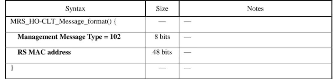
The third WiMAX MAC management message we defined is the MRS_HO-CLT (Mobile Relay Station Handover Complete). After the layer 2 network re-entry process is done by the MRS, it immediately sends the MRS_HO-CLT message to the successfully attached target BS. By this message, the target BS realizes that the layer 2 handover is done, and it can inform the new AR to start packet delivery. Table 3.3 shows MRS_HO-CLT message format we defined.
Table 3.3 MRS_HO-CLT message format
Syntax Size Notes
MRS_HO-CLT_Message_format() { — —
Management Message Type = 102 8 bits —
RS MAC address 48 bits —
} — —
3.2.2 Proposed messages in wired network
18
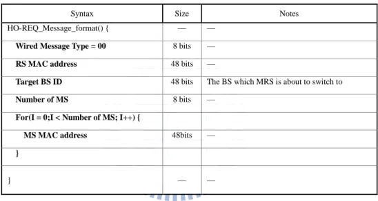
serving BS receive MRS_HO-REQ. The HO-REQ message is delivered from serving BS to PAR in order to notify the PAR that there is a MRS handover about to happen. In addition to MRS’s MAC address, this message also contains target BS’s identifier and MAC addresses of MSs attached to the MRS. The serving BS acquires these information and encapsulates them into PBU which will pass to the NAR latter. Note that the amount of MS attached to the MRS is uncertain, so there is 8 bits ―Number of MSs‖ to indicate how many MSs are there. The format of HO-REQ is shown in Table 3.4.
Table 3.4 HO-REQ message format
Syntax Size Notes
HO-REQ_Message_format() { — —
Wired Message Type = 00 8 bits —
RS MAC address 48 bits —
Target BS ID 48 bits The BS which MRS is about to switch to
Number of MS 8 bits —
For(I = 0;I < Number of MS; I++) {
MS MAC address 48bits —
}
} — —
Another message we propose in wired network is HO_RSP (Handover Response) message. This message is delivered from PAR to serving BS after the PAR receives PBA and established the tunnel to the NAR. The function of HO_RSP is to let serving BS to inform the MRS that the layer 2 handover can start operating. The format of HO_RSP is shown in Table 3.5.
Table 3.5 HO-RSP message format
Syntax Size Notes
HO-RSP_Message_format() { — —
Wired Message Type = 01 8 bits —
19
The other wired message proposed is HO-CLT (Handover Complete) message. After the target BS receives MRS_HO-CLT, which means the layer 2 network re-entry of MRS is completed, the target BS forward HO-CLT to inform the NAR. The main information contains in this message is the MAC address of MRS which complete the handover. Once the NAR receive HO-CLT, it can start forwarding packets to the MS. Table 3.6 shows the format of HO-CLT.
Table 3.6 HO-CLT format
Syntax Size Notes
HO-CLT_Message_format() { — —
Wired Message Type = 02 8 bits —
RS MAC address 48 bits —
} — —
3.2.3
Modified
Proxy
Binding
Update
and
Proxy
Binding
Acknowledgement
In our proposed procedure, the NAR requires knowing the information about the MRS and MSs connected to it, so that it can conduct IP layer handover for MSs. We encapsulate this information in PBU, including MRS’s MAC address, the home network prefixes and home addresses of all MSs. As a result, the original PBU which is defined in RFC 5213 [11], should be modified to support our scheme. The modified PBU format is shown in Table 3.8. Two flags are included in the reserved part of the message. If the F flag (stands for Fast handover scheme) is turned on, it means that our proposed fast handover scheme is used. On the other hand, when O flag (stands for handover mOde) is set to 0, it indicates that the predictive mode is in progress; when O flag is set to 1, it is in the reactive mode. In predictive mode, the information of MRS and MSs is carried in mobility options; while in reactive mode, PBU functions as a request so that the mobility
20
options carry less information. The format of mobility options is shown in Table 3.8. Table 3.7 Modified PBU message format
0 1 2 3
0 1 2 3 4 5 6 7 8 9 0 1 2 3 4 5 6 7 8 9 0 1 2 3 4 5 6 7 8 9 0 1 Sequence #
A H L K M R P F O Reserved Lifetime
Mobility options
Table 3.8 Mobility options for modified PBU message format
Syntax Size Notes
PBU_mobility_options_format() { — —
RS MAC address 48 bits —
If (O flag == 0) { — Predictive mode processing
IP version 1 bit Ip version used by MSs, 0 for v4 and 1 for v6
Number of MS 8 bits —
If (IP version == 0 ) { — IPv4
For (I = 0; I < Number of MS; I++) { — — MS IP address 32 bits —
Home prefix 32 bits —
HA address 32 bits —
} — —
} — — If (IP version == 1 ) { — IPv6
For (I = 0; I < Number of MS; I++) { — — MS IP address 128 bits —
Home prefix 128 bits —
HA address 128 bits —
} — —
21
The PBA message in [11] should also be modified. The F and O flags are also added into the reserved part of PBA. As mentioned above, PBA is replied by NAR as PBU’s return message in predictive mode. However in active mode, PBA is sent by PAR and it includes the information of MRS and MSs in its mobility options. The format of modified PBA and its mobility options are shown in Table 3.9 and Table 3.10, respectively.
Table 3.9 Modified PBA message format
0 1 2 3
0 1 2 3 4 5 6 7 8 9 0 1 2 3 4 5 6 7 8 9 0 1 2 3 4 5 6 7 8 9 0 1
Status K R P F O Reserved
Sequence # Lifetime
Mobility options
Table 3.10 Mobility options for modified PBA message format
Syntax Size Notes
PBA_mobility_options_format() { — —
RS MAC address 48 bits —
If (O flag == 1) { — Reactive mode processing
IP version 1 bit Ip version used by MSs, 0 for v4 and 1 for v6
Number of MS 8 bits —
If (IP version == 0 ) { — IPv4
For (I = 0; I < Number of MS; I++) { — —
MS IP address 32 bits —
Home prefix 32 bits —
HA address 32 bits —
22
} — — If (IP version == 1 ) { — IPv6
For (I = 0; I < Number of MS; I++) { — — MS IP address 128 bits —
Home prefix 128 bits —
HA address 128 bits —
} — — } — —
3.3 Proposed handover procedures
3.3.1 Predictive mode
In our proposed scheme, SDT is reduced by a network based cross-layering scheme in which the layer 2 and IP layer handover procedures are performed simultaneously, while packet loss can be avoided by a buffering mechanism. The proposed scheme enables the AR to conduct IP layer handover on behalf of all MSs under the MRS when the MRS performs layer 2 handover by exchanging management messages, including
MRS_HO-REQ/RSP, HO-REQ/RSP, MRS_HO-CLT, and HO-CLT between the BS, AR,
23
MS MRS Serving BS PAR Target BS NAR
1. MOB_NBR-ADV 3. MOB_MSHO-REQ 4. MOB_BSHO-RSP 5. MRS_HO-REQ 6. PBU 6. PBA Tunnel 8. MRS_HO-RSP 9. MOB_HO-IND
9. Layer 2 Network Re-entry
10. MRS_HO-CLT SDT 10. Packets forwarding 5. HO-REQ 7. HO-RSP 10.HO_CLT 2.Scanning process 6. Performing IP layer handover with HA
Figure 3.2 Predictive mode of proposed scheme
1. The serving BS (SBS) periodically broadcasts information about neighboring BSs using MOB_NBR-ADV (Mobile Neighbor Advertisement) message.
2. Upon receiving MOB_NBR-ADV, the MRS may perform a scanning process to monitor and measure the radio condition of neighbor BSs for a future handover.
3. Based on the signal strength or QoS parameters, the MRS may initiate handover by sending MOB_MSHO-REQ (Mobile MS Handover Request).
4. Through MOB_BSHO-RSP, the SBS can indicate one or more possible target BSs (TBSs) for MRS.
5. The MRS notifies the SBS that there is an impending layer 2 handover to the TBS through MRS_HO-REQ. By means of HO-REQ from the SBS, the previous AR (PAR) is informed that the MRS will move to the TBS.
6. Upon receiving HO-REQ, the PAR finds information of all MSs under the MRS, and sets up tunnel for all MSs by exchanging PBU/PBA messages with the NAR. Note that in PMIPv6 it requires one PBU per MS, but in the proposed scheme, the modified
24
PBU is responsible for all MSs. Afterwards, the PAR copies and forwards MSs’ packets to the NAR. Moreover, the home network prefixes and home addresses of all MSs are included in PBU, and the NAR will perform IP layer handover on behalf of those MSs with HAs.
7. Since IP layer handover is in progress and the tunnel is established, the PAR will notify the SBS to conduct further handover procedures through HO-RSP message. Moreover, the NAR will buffer packets coming from PAR for MSs to avoid packet loss in the subsequent handover procedures.
8. After receiving HO-RSP, the SBS notifies the MRS to conduct subsequent layer 2 switch process by MRS_HO-RSP.
9. The MRS sends MOB_HO-IND as a final indication of handover and performs the layer 2 HO procedure.
10. The MRS sends MRS_HO-CLT to the TBS immediately after finishing the Layer 2 HO process. Upon reception of MRS_HO-CLT, the TBS will notify the NAR of the MRS’s arrival by HO-CLT. When the NAR receives HO-CLT from the TBS, it will deliver the buffered packets to all MSs.
3.3.2 Reactive mode
If the MRS moves at high speed, the NAR may not receive PBU and set up tunnel with the PAR before the MRS conducts L2 RN process, therefore the packet loss may occur. In this situation, the NAR will exchange PBU/PBA with the PAR to set up bi-direction tunnel after it receives HO-CLT, and we call this reactive mode hereafter. Figure 3.3 illustrate a typical situation that reactive mode is triggered, and the whole procedure described as follows.
25
MS MRS Serving BS PAR Target BS NAR
1. MOB_NBR-ADV 3. MOB_MSHO-REQ 7. PBA 7. PBU Tunnel 4. MOB_HO-IND
5. Layer 2 Network Re-entry
6. MRS_HO-CLT SDT 8. Packets forwarding 6.HO_CLT 2.Scanning process 7. Performing IP layer handover with HA 4.MRS starts L2 handover too early Pkt loss
Figure 3.3 Reactive mode of proposed scheme
1. ~ 3. As explained in predictive mode, MOB_NBR-ADV is periodically broadcasted by SBS. After the possible scanning process, the MRS initiates the handover by sending MOB_MSHO-REQ message to SBS.
4. Due to the fast movement of MRS, there is no enough time for the PAR acquiring information to create PBU message. At this point, the MRS decides to start switching to the TBS. The MRS sends MOB_HO-IND and terminates the connection to SBS. 5. The MRS performs layer 2 network re-entry to the TBS without PAR and NAR
establishing a tunnel.
6. Once the MRS complete layer 2 network re-entry, it send MRS_HO-CLT message to the newly connected TBS. Then by sending HO_CLT message, the TBS informs the NAR that the MRS has connected to the new network.
7. The NAR requests information of MSs which is attached to the MRS by sending PBU to PAR. IP addresses, home network prefixes and HA addresses of MS are
26
encapsulated in PBA and sent back to NAR. Upon receiving PBA, the tunnel between PAR and NAR is established. At the same time, the NAR performs IP layer handover for all MSs. Note that the PBA and PBU have opposite functions compared with those in predictive mode.
8. The packets which are still sent to PAR are forwarded to NAR through the tunnel, and then the NAR forwards them to the MS. After the IP layer handover is finished, the bi-directional tunnels between the NAR and the HAs is created and the packets can be directly sent to the NAR.
27
Chapter 4 Numerical Analysis
In this chapter, we use mathematical calculation to analysis the performance of our proposed scheme as well as the schemes using Mobile IPv6 and Proxy Mobile IPv6. Next, we point out some parameters that affecting the performances and explain the benefit of proposed scheme over conventional ones.
4.1 Numerical calculation
In order to measure the processing time of mobile messages participate in all schemes, we design an experiment by developing a C++ program and executing on a layer 2 wireless access point device (WL-320gE). The messages measured include the original IEEE 802.16j messages (i.e. MOB_NBAR-ADV, MOB_MSHO-REQ, MOB_BSHO-RSP, and MOB_HO-IND) and the messages we proposed (i.e. MRS_HO-REQ, MRS_HO-RSP, and MRS_HO-CLT). Each message is executed 1 million times and the average processing time is calculated. The experiment results show that all the processing time is less than 10-2ms. In IEEE 802.16j, the layer 2 data is transferred frame by frame, thus the interaction of mobile messages is based on the frame duration. The common IEEE 802.16j frame duration is about 5ms, which is absolutely longer than the processing time of mobile messages. Therefore, we can assume that all transmission delay of mobile messages equals to one frame duration time (represent as Tframe). In other words, it is assumed that it takes Tframe for
messages exchanging between two wireless devices. Besides, the radio propagation delay is too small (about 10-2ms) that we omit it in the calculation.
Some other parameters used in the calculation are described as follows. TBS-AR, TAR-HA,
28
respectively. t is the average elapsed time from the MRS finishes L2 RN process to the MS sends a RtrSol. TL2, TDAD, and TF represent the L2 RN process delay, DAD process delay,
and packets forwarding delay, respectively. The delay between MS and BS equals twice
Tframe. The main factors contributing to the whole SDT are TAR-HA, TL2, and TDAD. All the
parameters are listed in Table 4.1.
Table 4.1 Parameters for calculation
parameter Description Used scheme
Tframe Frame duration of IEEE 802.16j All
TL2 Latency of IEEE 802.16j network re-entry procedure All
TF Forwarding delay of the first packet from NAR All
THO-IND Latency of the HO-IND message All
TBS-AR Latency between BS and AR All
TAR-HA Latency between AR and HA All
TDAD DAD process delay MIPv6
TRS/RA Latency of Router Solicitation plus Router Advertisement MIPv6/PMIPv6
TNS/NA Latency of Neighbor Solicitation plus Neighbor Advertisement MIPv6
TBU/Back Latency of Binding Update plus Binding ACK MIPv6
t Time elapsed from L2 re-entry finished to RtrSol is sent PMIPv6
TPBU/PBA Latency of Proxy Binding Update plus Proxy Binding Ack PMIPv6/proposed
TMRS_HO-CLT Latency of the MRS_HO-CLT message Proposed
THO_CLT Latency of the HO_CLT message Proposed
TPAR-NAR Latency between PAR and NAR Proposed
Dolap Overlap distance between Serving and Target BS All
29
The SDT is calculated at the MS fromthe reception of the last data packet from the PAR to the reception of the first data packet from the NAR . Hence, the SDT of using MIPv6, PMIPv6, and the proposed scheme can be calculated as follows:
(1) In MIPv6, there are six messages exchanged after the MRS finishes the layer 2 handover, including Router Solicitation, Router Advertisement, Neighbor Solicitation, Neighbor Advertisement, Binding Update and Binding ACK. The first four messages above are exchange between the MS and the NAR, which takes 2Tframe + TBS-AR. The other two
messages exchanged by the MS and HA take 2Tframe + TBS-AR + TAR-HA, so the total of them
is 12Tframe + 3TBS-AR + 2TAR-HA.The THO-IND equals 1Tframe and TF equals 2Tframe + TBS-AR +
TAR-HA. Besides, the DAD processing time done by NAR and layer 2 re-entry processing
time should be added. As a result, the SDT in MIPv6 can be expressed as follows.
SDTMIPv6 = THO-IND + TL2 + TRS/RA + TNS/NA + TDAD + TBU/Back + TF
= 15Tframe + 7TBS-AR + 3TAR-HA + TL2 + TDAD
(2) In PMIPv6, after the MRS finishes layer 2 handover, the process idles for an uncertain time until the RtrSol periodically broadcast by NAR is received. The factor t which represent the above elapse time must be considered. The latency of RtrSol plus RtrAdv,
which are exchanged between the MS and NAR equals 4Tframe + 2TBS-AR. PBU and PBA
are exchange between NAR and HA, so the latency is 2TAR-HA. Finally, the THO-IND equals
1Tframe and TF equals 2Tframe + TBS-AR. The SDT in PMIPv6 ca n be expressed as follows.
SDTPMIPv6 = THO-IND + TL2 + t + TRS/RA + TPBU/PBA + TF
30
(3) In the predictive mode of proposed scheme, after the MRS completes layer 2 handover, there are only MRS_HO-CLT message and HO-CLT message delivered from MRS to target BS then to NAR. Thus, the latency of the two messages is 1Tframe + 1TBS-AR. The
THO-IND equals 1Tframe and TF equals 2Tframe + TBS-AR. So the SDT of predictive mode can be
expressed as follows.
SDTProposed = THO-IND + TL2 + TMRS_HO-CLT + THO_CLT + TF
= 4Tframe + 2TBS-AR + TL2
(4) If the reactive mode is triggered in proposed scheme, the PBU and PBA messages are
exchanged between PAR and NAR during the SDT. Therefore, 2TPAR-NAR should be added
into the equation. In addition, the latency of first packet delivered by tunnel should also be added, which equals 1TPAR-NAR. The following is the expression of reactive mode.
SDTProposed_re = THO-IND + TL2 + TMRS_HO-CLT + THO_CLT + TPBU/PBA + TF
= 4Tframe + 2TBS-AR + TL2 + 3TPAR-NAR
For our analysis, the Tframe is assumed 5 ms, and the other parameters used are: TL2 =
220 ms, TBS-AR = 1 ms, TPAR-NAR = 4 ms, and TDAD = 1000 ms.
4.2 Numerical analysis results
Figure 4.1 shows the impact of TAR-HA on SDT. It can be observed that both MIPv6 and
PMIPv6 are affected by the change in delay between AR and HA because they need to exchange messages including BU/BAck or PBU/PBA to/from the HA. In contrast, the
31
proposed scheme is not affected because the HA is not involved in mobility-related signal after MRS finishes L2 RN procedure. In particular, it is worth noting that the SDT of MIPv6 is significantly larger than that of the proposed scheme due to the considerably longer DAD process time relative to the delay caused by other factors affecting SDT. In addition, the SDT in PMIPv6 is affected by t which can be affected by the interval of RtrSol (4 seconds [16]). Increasing t would result in growing SDT in PMIPv6. The main factor contributing to the SDT of the proposed scheme is TL2; however, the TL2 can be reduced to less than 220 ms
depending on whether L2 RN optimization defined in the standard is used or not.
Figure 4.1 Impact of AR-HA delay on SDT
The number of lost packets and the required buffer size for proposed scheme can be represented as λ × SDT and λ × (SDTProposed + TBS-AR + Tframe), respectively, where λ is the
average packet arrival rate. Since the number of lost packets is affected by SDT which can be affected by the TAR-HA. Figure 4.2 shows the impact of TAR-HA on packet loss with the traffic
32
influenced by the TAR-HA. Since the proposed scheme uses a buffering mechanism, the number
of lost packets is 0. Particularly, when the proposed scheme operates in the reactive mode, few packets may be lost. In addition, the MIPv6 and PMIPv6 experienced higher packet loss due to their higher SDT as shown in Figure 4.2.
Figure 4.2 Impact of AR-HA delay on #lost packets
The SDT and number of lost packets in the proposed scheme are affected by the velocity of MRS ( ), the overlap distance ( between two BSs, and handover preparation latency ( ). When MRS moves in the overlap area, it performs the handover preparation as well as handover decision and initiation procedures. At the edge of this area, MRS must execute the handover process (Figure 4.3). Therefore, the relation between , , and can be expressed as . If velocity of MRS exceeds the threshold (i.e., ), the proposed scheme will operate in reactive mode.
33 Vehicle Serving BS MRS Target BS MS 1 Dolap MS 3 MS 2
Figure 4.3 Overlap between two BSs
The handover preparation latency can be calculated as = 5Tframe + 2TBS-AR +
2TPAR-NAR + Tscan, where Tscan is the scanning process delay. Figure 4.4 shows the impact
of Tscan on the proposed scheme with different , it indicates that even with = 10 m and Tscan = 400 ms, the proposed scheme is still in nonreactive mode when is no larger
than 82 km/hr. Since usually the will be larger than 10 m and Tscan will be less than
400 ms, the proposed scheme will be in nonreactive mode with common vehicle speed.
34
Chapter 5 Simulation and Results
5.1 Simulation environment
In this chapter, we develop a simulation environment based on NS-2 (version 3.31) network simulator [17]. In order to match our network scenario, we install two additional modules on the NS-2, which are Secure Mobility Module designed by National Institute of Standards and Technology (NIST) and Light WiMAX Simulator (LWX) Module [19]. LWX can support IEEE 802.16 and IEEE 802.16j standards. Also, LWX provides 802.16 MAC functionalities with QoS, different modulation coding rates, and traffic relay supports are mainly used for bandwidth allocation and relay link selection researches. LWX also provides several bandwidth allocation algorithms for 802.16 and 802.16j networks including strict priority and round robin bandwidth algorithms for basic 802.16 network and round robin bandwidth algorithm for 802.16j relay network [19].
We modify the above program and add the proposed control messages to implement our proposed handover scheme. The detail of simulation network topology is shown in Figure 5.1, in which a MRS is mounted on a vehicle and moves from a SBS to a TBS in a different IP subnet. Note that the links between routers and ISP network have 100Mbps bandwidth and 3ms delay, and the links between BSs and ARs have 100Mbps bandwidth and 1ms delay.
35
ISP Network
100Mbps
3ms
100Mbps,1ms
100Mbps,1ms
100M
bps
3ms
100M
bps
3ms
Serving BS
MRS
MRS
MS
MS
Moves
HA
PAR
NAR
Target BS
Figure 5.1 Network topology for simulation.
In order to observe the performance of proposed scheme, we choose VoIP as our simulation target, because VoIP is a typical real time application people usually use on public transportation system. We set the traffic source parameters according to general VoIP, in which the MS receives downlink traffic that has 64 Kbps of constant bit rate and 200 bytes of packet size. All the parameters we used in NS-2 are shown in Table 5.1.
Table 5.1 Simulation parameters
Parameter Value
Channel type WirelessChannel
Radio propagation model TwoRayGround Network interface type WirelessPhy
36
Interface queue type PriQueue
Link layer type LL
Antenna model OmniAntenna
Max packet in ifq 50
Routing protocol AODV
Bandwidth allocation algorithm Round Robin for Relay
Framd duration 5 ms
Traffic type UDP/CBR
Packet size 200 bytes
Bit rate 64Kbps
5.2 Simulation results
In the simulation, the traffic starts at 0 second and each packet of it is assigned a sequence number. We record the receiving time of each packet in the simulation program, so that we can indicate which packets are lost and can also find out the period that packets cannot be delivered. After the results are obtained, we draw charts to show the relationship of packet’s sequence number and receiving time in all schemes. The result of MIPv6 is shown in Figure 5.2. And the results of PMIPv6 (t = 0, t = 2, t = 4) are shown in Figure 5.3, 5.4, and 5.5. Next, the results of proposed scheme in predictive mode and reactive mode are shown in Figure 5.6 and 5.7 respectively. Finally, we give a comparison of all schemes in a Table 5.2 and analysis the simulation result.
37
Figure 5.2 Packet sequence number to receiving time in MIPv6 scheme
Figure 5.3 Packet sequence number to receiving time in PMIPv6 (t=0) scheme
38
Figure 5.5 Packet sequence number to receiving time in PMIPv6 (t=4) scheme
Figure 5.6 Packet sequence number to receiving time in proposed scheme (predictive mode)
39
Table 5.2 SDT and packet loss in all schemes
Protocol MIPv6 PMIPv6 Proposed Scheme
t = 0 t = 2 t = 4 Pre. Re. Cal. SDT (ms) 1320 276 2276 4276 242 254 Sim. SDT (ms) 1325 275 2275 4275 240 255 #Lost Packets 52 10 90 170 0 9 Improvement of SDT 81.9% 12.7% 89.5% 94.4% - -
Figure 5.8 Comparison of SDT in calculation and simulation
In Table 5.2, the first and second rows show the SDT results by calculation and simulation respectively. We can observe that compared with the numerical results calculated in Chapter 4, the simulation result in each scheme has similar value (less than 5 ms). Moreover, as can be seen in Figure 5.8, the trends of all schemes are approximately identical in calculation and simulation. Therefore, we can say that the
0 500 1000 1500 2000 2500 3000 3500 4000 4500 Cal. SDT (ms) Sim. SDT (ms)
40
calculation and simulation results confirmed each other.
In the MIPv6 approach, the SDT is 1325 ms because the layer 2 network re-entry and IP layer handover procedures are performed sequentially. A higher packet loss (i.e., 52 packets) in the MIPv6 approach is observed because of no buffering mechanism and long SDT. Although layer 2 network re-entry and IP layer handover procedures are also performed sequentially in PMIPv6 approach, the SDT is reduced to 275 ms when t = 0 because the MS always uses the home address without DAD process. In addition, 10 packets are lost in PMIPv6 approach because there is no buffering mechanism.
The SDT in the proposed scheme is less than 255 ms because the cooperation of layer 2 and IP layer forces IP layer handover procedures to be performed before the MRS switches to TBS. Moreover, packet loss did not occur in the proposed scheme with nonreactive mode because the MSs’ packets are forwarded to NAR and sent to MSs after the NAR receives a HO-CLT. When the proposed scheme operates in the reactive mode, 9 packets are lost because the bi-direction tunnel won’t be established until the MRS finishes the L2 RN process. As compared with the MIPv6 and PMIPv6 approaches, the SDT is reduced by approximately 81.9% and 89.5%, respectively and there is no packet loss in the proposed scheme under nonreactive mode.
41
Chapter 6 Conclusions
In this thesis, we first point out the defects of MIPv6 and PMIPv6. In IEEE 802.16j MRS mode, When a MRS and MSs attached to it handover to another BS, high packet loss rate and long SDT may occurs in both scheme. Although there are some amendments of PMIPv6 which improve the performance, these methods cannot apply to IEEE 802.16j in MRS mode. Therefore, we proposed a network-based fast handover mechanism which uses cross-layering design to solve the above problem.
In the proposed scheme, there are some control messages added in order to let the IP layer handover and the layer 2 handover to cooperate. By the mathematical calculating, we can see that the proposed method has shorter SDT and less packet loss than those in MIPv6 and PMIPv6. The main reasons are that there is no DAD process time, and the delay between AR and HA does not influence performance of the proposed handover scheme. Next, we develop a NS-2 network environment to observe the performance of all schemes. The results show that the proposed scheme has 0 (or very less) packet loss and the SDT is reduced by approximately 81.9% and 89.5% compared to MIPv6 and PMIPv6.
In spite of the remarkable achievement of our proposed scheme, there are some future works to improve the performance even more. For example, we can design a optimize layer 2 re-entry process. Besides, packet loss still occurs in reactive mode, so a mechanism to optimize the reactive mode may be necessary. Furthermore, we plan to do some in depth research on practically deploying our proposed scheme on the current WiMAX system, and come up with some experiments to test the real user experience when using the proposed scheme.
42
References
[1] WiMAX Forum® ; http://www.wimaxforum.org/
[2] IEEE Std 802.16e-2005, “IEEE Standard for Local and metropolitan area
networks-Part 16: Air Interface for Fixed and Mobile Broadband Wireless Access Systems”, December 2005
[3] IEEE 802.16’s Relay Task Group; http://wirelessman.org/relay/
[4] IEEE Std. 802.16j, “Local and Metropolitan Area Networks, Part 16: Air Interface
for Fixed Broadband Wireless Access Systems, Multihop Relay Specification” , June
2009
[5] V. Genc, et al., “IEEE 802.16J relay-based wireless access networks: an overview” IEEE Wireless Communications, 15(5), pp. 56-63, October 2008
[6] D. Soldani, and S. Dixit, “Wireless relays for broadband access”, IEEE Communications Magazine, 46(3), pp. 58-66, March 2008
[7] Internet Engineering Task Force; http://www.ietf.org/
[8] C. Perkins, D. Johnson, and J. Arkko, “IP Mobility Support for IPv4, Revised”, RFC 5944, November 2010; http://tools.ietf.org/html/rfc5944
[9] D. Johnson, C. Perkins, and J. Arkko, “Mobility support for IPv6”, RFC6275, July 2011; http://tools.ietf.org/html/rfc6275
[10] J. Arkko, V. Devarapalli, and F. Dupont. “Using IPsec to Protect Mobile IPv6
Signaling Between Mobile Nodes and Home Agents”, RFC 3776. June 2004; http://tools.ietf.org/html/rfc3776
[11] S. Gundavelli, K. Leung, V. Devarapalli, K. Chowdhury, and B. Patil, "Proxy Mobile
IPv6", RFC5213, August 2008; http://tools.ietf.org/html/rfc5213
43 May 2010; http://tools.ietf.org/html/rfc5844
[13] K.-S. Kong, Y.-H. Han, M.-K. Shin, H. R. Yoo, and W. Lee, “Mobility Management
for All-IP Mobile Networks: Mobile IPv6 vs. Proxy Mobile IPv6”, IEEE Wireless
Communications, 15(2), pp. 36-45, April 2008
[14] H. Yokota, K. Chowdhury,, R. Koodli, B. Patil, and F. Xia, “Fast Handovers for
Proxy Mobile IPv6”, IETF RFC 5949, September 2010
[15] S. Sim, S.-J. Han, J.-S. Park, and S.-C. Lee, “Seamless IP mobility support for flat
architecture mobile WiMAX networks”, IEEE Communications Magazine, 47(6), pp.
142-148, June 2009
[16] T. Narten, E. Nordmark, and W. Simpson, “Neighbor Discovery for IP Version 6
(IPv6)” , IETF RFC 2461, December 1998
[17] Network Simulator - ns-2; http://www.isi.edu/nsnam/ns/
[18] National Institute of Standards and Technology; http://www.nist.gov/index.html