IEEE SIGNAL PROCESSING LETTERS, VOL. 10, NO. 10, OCTOBER 2003 307
An Efficient Design of a Variable Fractional Delay
Filter Using a First-Order Differentiator
Soo-Chang Pei, Fellow, IEEE, and Chien-Cheng Tseng, Senior Member, IEEE
Abstract—In this letter, the Taylor series expansion is used to transform the design problem of a fractional delay filter into the one of a first-order differentiator such that the conventional finitie-impulse response and infinite-finitie-impulse response differentiators can be applied to design a fractional delay filter directly. The proposed structure is more efficient than the well-known Farrow structure in terms of filter coefficient storage because only one first-order differentiator needs to be designed and implemented. Moreover, one design example is demonstrated to illustrate the effectiveness of this new design approach.
Index Terms—Differentiator, fractional delay filter.
I. INTRODUCTION
I
N MANY applications of signal processing, there is a need for a delay that is a fraction of the sampling period. These applications include time adjustment in digital receivers, beam steering of antenna array, speech coding and synthesis, mod-eling of music instruments, sampling rate conversion, time delay estimation, comb filter design, analog–digital conversion, etc. [1]–[10]. An excellent survey of the fractional delay filter design is presented in tutorial papers [3], [4]. The desired frequency re-sponse of the variable fractional delay filter is given by(1) where delay is an integer, and is a variable or adjustable fractional number in the range . So far, there have been several methods to design variable fractional delay finite-impulse response (FIR) filters. In [5], the transfer function of the FIR filter used to approximate this specification is chosen as follows:
(2)
where are the polynomial functions in of degree , i.e.,
(3)
Manuscript received August 20, 2002; revised November 5, 2002. The as-sociate editor coordinating the review of this manuscript and approving it for publication was Dr. Petr Tichavsky.
S. C. Pei is with Department of Electrical Engineering, National Taiwan Uni-versity, 106 Taipei, Taiwan, R.O.C. (e-mail: [email protected]).
C. C. Tseng is with Dept. of Computer and Communication Engineering, Na-tional Kaohsiung First University of Science and Technology, 824 Kaohsiung, Taiwan, R.O.C. (e-mail: [email protected]).
Digital Object Identifier 10.1109/LSP.2003.815616
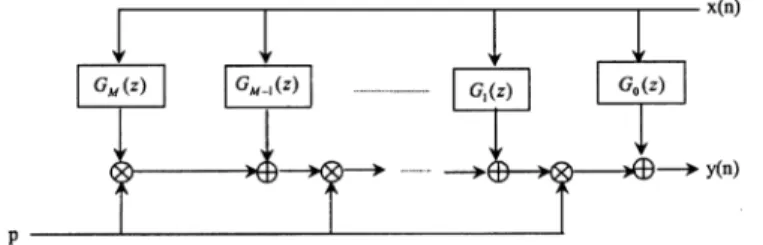
Fig. 1. Farrow structure for fractional delay filters with adjustable delayp.
Substituting (3) into (2), the transfer function can be rewritten as
(4)
where . In [5]–[10], several approaches
have been proposed to design subfilters for such that the filter approximates the de-sired response as well as possible. Once the subfilters have been designed, the filter can be implemented by the efficient Farrow structure shown in Fig. 1 [5].
On the other hand, the digital differentiator has been a very useful tool to determine and estimate the time derivatives of a given signal. For example, in radar and sonar applications, the velocity and acceleration are computed from position mea-surements using differentiators [11]. In biomedical engineering, it is often necessary to obtain the higher order derivatives of biomedical data, especially at low-frequency ranges [12]. Until now, several methods have been developed to design infinite-im-pulse response (IIR) and FIR digital differentiators such as the Remez exchange algorithm [13], eigenfilter method [14], least squares method [15], [16], quadratic programming [17], etc. In this letter, the Taylor series expansion will be used to transform the design problem of the fractional delay filter into that of a first-order differentiator such that conventional FIR and IIR dif-ferentiators can be applied to design the fractional delay filter di-rectly. The proposed structure is more efficient than the Farrow structure in Fig. 1 in terms of filter coefficient storage because only one first-order differentiator needs to be designed and im-plemented instead of subfilters. Finally, it is worth men-tioning that the idea of implementing a fractional delay filter or interpolation with various-order differentiators is not new. The related researches can be found in [18] and [19]. However, in this letter, the idea of only using the single first-order differen-tiator is novel.
1070-9908/03$17.00 © 2003 IEEE
308 IEEE SIGNAL PROCESSING LETTERS, VOL. 10, NO. 10, OCTOBER 2003
II. DESIGNMETHOD
In this section, we will use the Taylor series expansion to transform the design problem of the fractional delay filter into the one of a first-order differentiator. The main idea is based on the following fact.
Fact: If the frequency response of the first-order
differen-tiator is denoted by and delay ,
then it can be shown that the fractional delay filter can be written as
(5) where , are two prescribed integers, and denotes a term which goes to zero at least as when approaches zero.
Proof: Using the Taylor series expansion, the term
can be expressed as a polynomial of as follows:
(6)
By multiplying both sides by the factor , we get the fol-lowing equality:
(7)
Substituting into (7) and using equality , we get
(8)
Because the fractional number is in the range , the term approaches zero when is very large. Thus,
TABLE I
THENRMS ERROR FORVARIOUSM
the ideal response of the fractional delay filter can be approxi-mated by the following form:
(9)
The larger is, the better approximation that has. In order to evaluate the performance of this approximation, the normalized root mean square (NRMS) error is defined by
NRMS
(10) It is easy to show
and , so
the NRMS only depends on the choice of and . Table I lists the NRMS for various and . From this result, it can be found that when , the NRMS is less than 0.1%. Thus, the approximates the ideal response
very well for .
Now, let us describe how to design a variable filter to approximate . From (9), we see that if a filter is designed to approximate the first-order differentiator response
, then the following filter
(11)
approximates well. Based on (11), the fractional delay filter can be implemented by the same first-order
differen-tiator and integer delay shown in Fig. 2.
Thus, the design problem reduces to the design of first-order differentiator . In the literature, several methods have been proposed to design FIR and IIR differentiator [13]–[17]. Once has been designed and inserted into the structure in Fig. 2, we can easily adjust the fractional number to obtain the desired delay response. Now, three aspects of the efficiency are used to compare the Farrow structure in Fig. 1 with the proposed structure in Fig. 2.
1) Computational complexity: The Farrow structure has subfilters , but our structure has filters
PEI AND TSENG: EFFICIENT DESIGN OF A VARIABLE FRACTIONAL DELAY FILTER USING A FIRST-ORDER DIFFERENTIATOR 309
Fig. 2. Proposed structure for the fractional delay filter. TheG(z) is the first-order differentiator.
and scalar multiplications. Thus, both structure almost have the same arithmetic complexity.
2) Delay of filter: In Farrow structure, the integer delay is fixed and specified in advance, but the delay in our structure is equal to . Thus, when the number of sub-filters is large, the delay of the proposed structure is longer than the delay of Farrow structure.
3) Storage requirement: For the implementation of Farrow structure, there are the coefficients of subfilters necessary to be stored in the memory. However, for the proposed structure, only the coefficients of a single first-order differentiator need to be stored in the memory. Thus, the proposed structure is more efficient than the Farrow structure in terms of the filter coefficient storage.
III. DESIGNEXAMPLE
In this section, an example performed with MATLAB lan-guage in an IBM-compatible personal computer is presented to illustrate the effectiveness of the proposed design method. To evaluate the performance, the maximum absolute error and rms error are defined by
(12)
where error
(13) In this example, the parameters are chosen as , ,
and . Thus, the integer delay . Now,
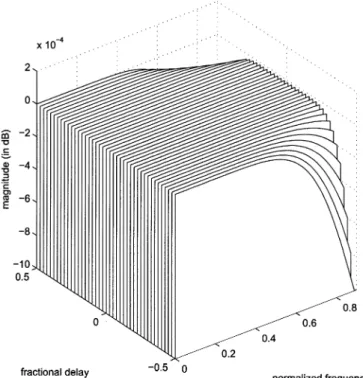
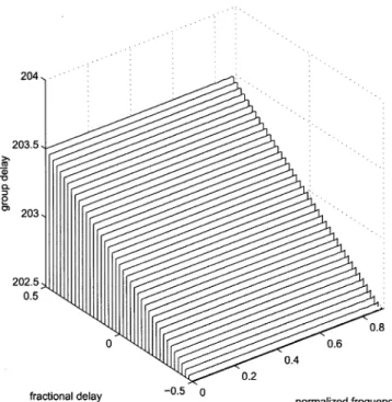
the least squares method in [16] is used to design linear phase FIR differentiator with length and passband edge frequency . Fig. 3 shows the magnitude response of the designed first-order differentiator . Clearly, ap-proximates the ideal response well in the range . By inserting the designed differentiator into the struc-ture in Fig. 2, the variable fractional delay filter can be obtained. Figs. 4 and 5 depict the magnitude response in decibel scale and group delay of the designed variable fractional delay filter in the frequency range for
dif-ferent . The maximum absolute error is
Fig. 3. Magnitude response of the designed first-order differentiatorG(z).
Fig. 4. Magnitude response of the designed variable fractional delay filter H(z; p).
and rms error is . Because the
errors are very small, the specification is well fitted.
Finally, it is interesting to compare the performance of the proposed structure with conventional Farrow structure under the same arithmetic complexity. Because filter in Farrow structure is nonlinear phase, there are multiplications needed to implement . In the above example, the first-order differentiator is linear phase with length , so there are multiplications needed to implement differentiator
310 IEEE SIGNAL PROCESSING LETTERS, VOL. 10, NO. 10, OCTOBER 2003
Fig. 5. Group delay response of the designed variable fractional delay filter H(z; p).
. Thus, when we choose , the filters in both structures have the same arithmetic complexity. Now, the con-ventional weighted least squares method in [7] is used to design filters in Farrow structure with specification , and uniform weighting. As a result, the
max-imum absolute error is and rms error
is . Thus, the proposed structure has smaller de-sign errors than the Farrow structure under the same arithmetic complexity. However, the delay of Farrow structure is 15, but the delay of our structure is . Thus, the proposed structure has longer delay than the Farrow structure.
IV. CONCLUSION
In this letter, the Taylor series expansion has been used to transform the design problem of the fractional delay filter into the one of a first-order differentiator such that the conventional digital differentiators can be directly applied to design a frac-tional delay filter. The proposed structure is more efficient than the well-known Farrow structure in terms of filter coefficient
storage because only a single first-order differentiator needs to be designed and implemented.
REFERENCES
[1] S. C. Pei and C. C. Tseng, “A comb filter design using fractional sample delay,” IEEE Trans. Circuits Syst. II, vol. 45, pp. 649–653, June 1998. [2] K. Rajamani, Y. S. Lai, and C. W. Farrow, “An efficient algorithm for
sample rate conversion from CD to DAT,” IEEE Signal Processing Lett., vol. 7, pp. 288–290, Oct. 2000.
[3] T. I. Laakso, V. Valimaki, M. Karjalainen, and U. K. Laine, “Splitting the unit delay: Tools for fractional delay filter design,” IEEE Signal Pro-cessing Mag., vol. 13, pp. 30–60, Jan. 1996.
[4] V. Valimaki and T. I. Laakso, “Principle of fractional delay filters,” in Proc. ICASSP, May 2000, pp. 3870–3873.
[5] C. W. Farrow, “A continuously variable digital delay element,” in Proc. Int. Symp. Circuits and Systems, 1988, pp. 2641–2645.
[6] A. Tarczynski, G. D. Cain, E. Hermanowicz, and M. Rojewski, “WLS design of variable frequency response FIR filters,” in Proc. Int. Symp. Circuits and Systems, 1997, pp. 2244–2247.
[7] W. S. Lu and T. B. Deng, “An improved weighted least-squares design for variable fractional delay FIR filters,” IEEE Trans. Circuits Syst. II, vol. 46, pp. 1035–1040, Aug. 1999.
[8] T. B. Deng, “Discretization-free design of variable fractional-delay FIR filters,” IEEE Trans. Circuits Syst. II, vol. 48, pp. 637–644, June 2001. [9] J. Vesma and T. Saramaki, “Design and properties of polynomial-based fractional delay filters,” in Proc. Int. Symp. Circuits and Systems, 2000, pp. I-104–I-107.
[10] C. C. Tseng, “Design of variable fractional delay FIR filter using differ-entiator bank,” in Proc. Int. Symp. Circuits and Systems, vol. 4, 2002, pp. 421–424.
[11] M. I. Skolnik, Introduction to Radar Systems. New York: McGraw-Hill, 1980.
[12] S. Usui and I. Amidror, “Digital lowpass differentiation for biological signal processing,” IEEE Trans. Biomed. Eng., vol. BME-29, pp. 686–693, 1982.
[13] T. W. Parks and J. H. McClellan, “Chebyshev approximation for non recursive digital filters with linear phase,” IEEE Trans. Circuit Theory, vol. CT-19, pp. 189–194, Mar. 1972.
[14] S. C. Pei and J. J. Shyu, “Eigenfilter design of higher-order digital differ-entiators,” IEEE Trans. Acoust. Speech Signal Processing, vol. 37, pp. 505–511, 1989.
[15] S. Sunder and V. Ramachandra, “Design of equiripple nonrecursive digital differentiators and Hilbert transformers using a weighted least-squares technique,” IEEE Trans. Signal Processing, vol. 42, pp. 2504–2509, Sept. 1994.
[16] G. Mollova, “Compact formulas for least-squares design of digital dif-ferentiators,” Electron. Lett., vol. 35, no. 20, pp. 1695–1697, Sept. 1999. [17] C. C. Tseng, “Stable IIR digital differentiator design using iterative quadratic programming approach,” Signal Process., vol. 80, pp. 857–866, 2000.
[18] F. Harris, “Performance and design considerations of the Farrow filter when used for arbitrary resampling of sampled time series,” in Proc. 31st Asilomar Conf. Signals, Systems, and Computers, vol. 2, Nov. 1997, pp. 1745–1749.
[19] R. Sudhakar, R. C. Agarwal, and S. C. Dutta Roy, “Time domain in-terpolation using differentiators,” IEEE Trans. Acoust. Speech Signal Process., vol. ASSP-30, pp. 992–997, Dec. 1982.