IP DESIGN OF A RECONFIGURABLE BASELINE
JPEG CODING
Hao-Chieh Chang, Li-Lin Chen, Chung-Jr Lian, Yung-Chi Chang and Liang-Gee Chen DSP/IC Design Lab, Department of Electrical Engineering
National Taiwan University Taipei, Taiwan, R.O.C.
E-mail: {howard, lilin, Igchen} @video.ee.ntu.edu.tw
Abstract
IP design of a complete, re-configurable baseline JPEG encoder is presented in this paper It features completely JFIF (JPEG File Interchange Format) compatible bit-stream output and a user-defined quantization table that can be re-configured at the run time and the compiling time. Thus, various hardware configurations can be easily achieved. Besides, modularized design is practiced such that smooth data
flow in this pipelined architecture can be easily
achieved by utilizing a central controller: This technique improves system performance much.
I.
INTRODUCTION
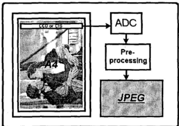
This paper describes an IP design of an image encoding hardware architecture based on the baseline JPEG [ 11 standard, which is the international standard for continuous-tone still image coding. Such an image encoding hardware is required for more and more data-intensive image transmission applications, such as high-resolution color image scanners and digital cameras with million-pixel resolution. One example of these applications, a color scanner system, is shown in Figure 1. In these applications, data rate can reach several gigabits per second, even higher than the rate of current video applications, like MPEGVMPEG-2 [2] video. Such data rate is too large for the bandwidth between the host computer and I/O Devices. In the current I/O transmission scheme, up to lOOMbits bandwidth in Ultra SCSI 110 bus, it will cost several minutes to transmit the image data from I/O device to PC. Even more, higher resolution image sensing becomes more demanded in the future. Thus, in order to overcome the long transmission latency, image data compression is
required for these high-resolution image-processing applications.
b 1
Figure 1. Scanner application with embedded JPEG encoder IP
For the applications such as color scanners and digital cameras with compression capability embedded, a dedicated architecture with hardware-optimized configuration will be the cost-effective solution. It consumes less chip area and power. However, various applications demand different compression performance. Some demand higher image quality while others focus on compression efficiency. Thus, reconfigurable hardware architecture is a more flexible solution for these applications. This motivates the proposed IP design of image compression.
This paper is organized as follows. The adoption of JPEG standard as image compression algorithm is. briefly described in section 2. Section 3 presents the proposed architecture of the JPEG encoder IP and the
system integration issues. In section 4, the simulation results are summarized. Finally, a conclusion is given.
11. JPEG STANDARD
In the past, many image compression algorithms have been derived, such as DCT-based, VQ-based and wavelet-based algorithms. Several of them have presented very good compression-to-quality performance. However, most of them are not standardized. This limits the exchange of compressed data. In other words, further processing is required to make the compressed data portable. In order to avoid possible conflict of various compressed image data and to provide a widespread image interchange format, a family of coding algorithms for continuous- tone still image and . the bit-stream structure for representing compressed data are defined by Joint Photographic Expert Group (JPEG) of International Standard Organization (ISO). Besides, JPEG features an easy tradeoff between desired compression and image quality. Accordingly, it is very suitable for various image compression applications.
111. IP ARCHITECTURE
This JPEG IP core architecture can be divided as
three major parts: the 2-D 8x8 Discrete Cosine Transform (DCT), re-configurable Quantization and the Zig-Zag Scan module, and the VLC (Huffman Coding) encoder module. The block diagram of JPEG encoder is shown in the Figure 2. The hardware architecture is briefly described as follows.
...
HuffmanFigure 2. Block Diagram of JPEG Encoder
A. Core Pipelined Architecture
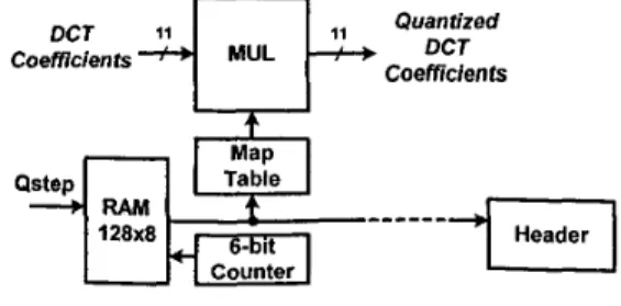
A cost-effective 2-D 8x8 DCT module can be implemented by using Chen's algorithm [3], i.e., the row-column decomposition that separates the 2-D DCT into two I-D DCT. Using the row-column decomposition method can reduce the computation amount much. The computation complexity is reduced from 0 (N4) to 0 @I3). In addition, the 1-D hardware module can be reused by properly scheduling the data flow. Zig-Zag scan is implemented by using a random logic circuit to store the scanning order and a 64x 11 dual-port SRAM to reorder the input sequence. Re-configurable quantization is implemented by utilizing a QCoeff RAM that can be configured at run-time, 1/Q map table that also can be altered at compiling time, and a multiplier. The block diagram of such configuration is shown in Figure 3. While performing quantization, the quantization coefficients stored in QCoeff
RAM
address the 1/Q map table to obtain required inverse quantization coefficients. Then, inverse quantization coefficients are multiplied by DCT coefficients. The output data of the multiplier are ready to be encoded by the VLC encoder. VLC encoder comprises differential pulse code modulation (DPCM) module, run-length coding (RLC) module, VLC table, symbol-slicing module and bit-packing module.
DCT
4
MULQ"rEFd
Coefficients
Coefficients
I
I'I
CounterI
Figure 3. Reconfigurable Quantizer
Besides, JFIF-format header and marker producing module is designed to cooperate with the core
modules such that this JPEG core can produce completely JFIF compatible bit-streams. Figure 4 shows the block diagram of JFIF header module.
i width I I length I I grayk I -
L
I
I I I I I I I I I header I I I I I I I to pacB
:ker+
astap--- Header!
Figure 4. Block diagram of JFIF header module
The whole architecture is fully pipelined. High input data rate and throughput rate can be achieved by using such hardware configuration so as to meet the speed requirement for various applications. Control circuits are designed as a counter-based logic. It fhnctions like a data flow monitor to trace the data flow in the data path of the core architecture. Data flow can be easily monitored by such control circuits.
B. System Integration
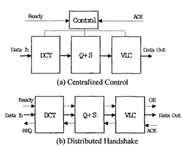
Soft IP is delivered in the form of synthesizable HDL code recommended by VSIA [4]. Flexibility is the most advantage for soft IP since it can be reused in various systems by resynthesizing it under various technologies. However, such feature is not enough for system integration. In order to build a system rapidly, robust and easy to be integrated IP is required. Since an actual system always works with exception like system stall, buffer overflow etc., IP designer should take these into consideration. Handshake mechanism is often adopted in actual system. It makes the data flow in a natural demand-supply way. Centralized control is another method. All pipeline registers are stalled when exception encountered and hence stall
the whole circuit. Figure 5 shows these two data-flow controls. Centralized control is easy to implement while handshake makes the control signal localized. In real simulation, handshake is somewhat less efficient. Thus, this design adopts the centralized control.
... &-&Dl ...
PM
-: ...
U
(a) Centralized Control
Dah h
...
(b) Distributed Handshake Figure 5 . System data-flow control
IV. SIMULATION RESULTS
The entire JPEG encoder core is implemented and simulated at RTL-level and transistor level. It is synthesized witha
3-layer 0.6um CMOS standard cell library. The synthesized modules comprise approximately 28,000 gates, excluding one 64x 1 1 bit dual-port SRAM for zigzag scanning and one 64x 16 bit single-port SRAM used as the DCT transpose memory.Table 1. Area and simulated time-delay of all modules used in JPEG encoder.
Table 1 shows the final synthesis results for the
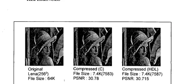
various modules of JPEG encoder. Analyzed area and simulated critical path time-delay of all modules are shown. The maximum simulated clock rate can reach 50 MHz. Because this JPEG encoder can process one sample per clock cycle, a very high data input rate, 50 MHz, can be achieved. Thus, by using this architecture, an A4 600dpi color image can be processed in few seconds. Figure 6 illustrates the compressed images produced by the software and hardware implemented encoder respectively.
V.
CONCLUSIONS
A Soft IP design of re-configurable JPEG encoder architecture is described in this paper. Compared with other programmable JPEG encoder architectures [5],[6],[7], this design is more compact in chip sizekost. Moreover, a central controller simplifies the control of data flow. Thus, for various applications, an image compression system can be rapidly built based on the proposed JPEG core architecture.
REFERENCES
[ l ] ISOIIEC, Int. Standard DIS 10918, “Digital
compression and coding of continuous-tone still images.”
Didier Le Gall. “MPEG: A video Compression Standard for Multimedia Applications,” Communications of the ACM, Vol. 34, No. 4, pp.46-58, April 1991.
Avanindra Madisetti and Alan
N.
Willson, Jr,“A 100 MHz 2 - 0 8x8 DCTIIDCT Processor for HDTV Applications,” IEEE Trans. on Circuit
and System for Video Technology, Vol. 5, No. 2, pp. 158-164, April 1995.
Virtual Socket Interface Alliance Architecture Document. V 1 .O, March, 1997
Peter A. Ruetz, Po Tong, Daniel Luthi and Peng Hang, “A video-Rate JPEG Chip Set,” Journal
of VLSI Signal Processing, No. 5, pp. 141-150, 1993.
Martin Bolton, Richard Boulton, John Martin, Samuel Ng and Steve Turner, “A Complete
Single-Chip Implementation of the JPEG Image Compression Standard,” IEEE 199 1 Custom
Integrated Circuits Conference.
Mario Kovac and
N.
Ranganathan, “JAGUAR:A Full Pipelined VLSI Architecture for JPEG Image Compression Standard,” Proceedings of
the IEEE, Vol. 83, No. 2, Feb. 1995 [2] [3] [4] [5] [6] [7]
Original Compressed (C) Compressed (HDL)
Lena(256*) File Size : 7.4K(7583) File Size : 7.4K(7587) File Size : 64K
,
PSNR : 30.78 PSNR: 30.715Figure 6. Compressed “Lena” images produced by software and hardware implemented baseline