Dar-Zen Chen
1 Professor e-mail: dzchen@ntu.edu.twWei-Ming Pai
Graduate Assistant Department of Mechanical Engineering, National Taiwan University, Taipei, Taiwan 10660, Republic of ChinaA Methodology for Conceptual
Design of Mechanisms by Parsing
Design Specifications
In this paper, design specifications for the conceptual design of mechanisms are parsed into three coherent categories: functional requirements, structural requirements, and de-sign constraints. Based on functional requirements, the functioning kinematic chain of a mechanism can be constructed by connecting the functioning links accordingly. From structural requirements, admissible kinematic structures are searched from the existing atlases of kinematic structures. Those admissible kinematic structures, which comprise at least one segment with the same characteristics of the functioning kinematic chain, are identified as compatible kinematic structures. Thus, feasible mechanisms that fulfill de-sign specifications can be yielded by labeling joints in the compatible kinematic struc-tures subject to design constraints. With this methodology, classified design specifications are used to guide designer through various stages of the conceptual design process in a systematic manner. The creation of the variable-stroke engine mechanism [Freudenstein, F., Maki, E. R., 1983, “Development of an Optimum Variable-Stroke Internal-Combustion Engine Mechanism From the Viewpoint of Kinematic Structure,” ASME J. Mech., Trans., Automat., Des., Vol. 105, pp. 259–267] is used as an illustrative example.
关DOI: 10.1115/1.2044767兴
1 Introduction
In the conceptual design of mechanisms, initial comprehension of an object mechanism is solely based on a set of given design specifications, in which what a mechanism should do关1兴 is de-scribed. From these design specifications, certain significant struc-tural characteristics of the mechanism, such as the degree-of-freedom共DOF兲, the number of links, the nature of motion, and the number of independent loops, etc., are usually classified as struc-tural requirements. Based strictly on strucstruc-tural requirements, Freudenstein and Maki关2兴 developed a systematic approach for the conceptual design of mechanisms, where admissible mecha-nisms are enumerated. Atlases of admissible kinematic structures, such as those of kinematic structures with up to six links关3,4兴, eight links关5,6兴, ten links 关7–11兴, and eleven links 关12兴 have been established during the past three decades. Following the enumera-tion of admissible kinematic structures, ground link is assigned and joint types are labeled in as many nonisomorphic ways as possible in search of candidate mechanisms. Since only structural requirements are used to enumerate candidate mechanisms in this approach, the needs for human ingenuity and experience involved can be substantially alleviated. Functional requirements together with design constraints are then used for further viability evalua-tion. As a result, feasible mechanisms that fulfill design specifica-tions are obtained by the way of rejecting those candidate mecha-nisms failed in the evaluation process. Figure 1 shows the procedure of this approach. This approach had been a major breakthrough in the pursuit of systematic approaches for the con-ceptual design of mechanisms, and had been widely applied to a variety of applications 关13–20兴. However, numerous infeasible mechanisms are subsumed since only structural requirements are considered in the enumeration of candidate mechanisms. Thus, in turn, it leads to circumstances, where infeasible mechanisms need to be carefully screened out from enumerated candidate mecha-nisms, resulting in a tedious and inefficient process.
In this paper, a systematic methodology for the conceptual de-sign of mechanisms is presented. As shown in Fig. 2, dede-sign specifications are classified as functional requirements, structural requirements and design constraints. Motion requirements of a set of functioning links, such as the ground, input and output links, are specified as functional requirements. Mapping functional re-quirements to the connections of functioning links, the function-ing kinematic chain of a mechanism can be constructed. On the other hand, based on structural requirements, admissible kine-matic structures of the mechanism are searched from the existing atlases of kinematic structures. By assigning the functioning kine-matic chain into admissible kinekine-matic structures subject to design constraints on locations of functioning links, compatible kine-matic structures can be identified. According to design constraints on joints of the mechanism, joints in those compatible kinematic structures are labeled to yield feasible mechanisms. With this pro-cedure, conceptual design of mechanisms can be performed in an efficient manner. The creation of the variable-stroke engine mechanism关13兴 is used as an example to demonstrate the meth-odology.
2 Classification of Design Specifications
Design specifications with various natures can be identified and classified into three coherent categories: functional requirements, structural requirements, and design constraints. Pahl and Beitz 关21兴 defined functional requirements as “the general input/output relationship of a mechanism whose purpose is to perform a task.” Suh关22兴 deemed functional requirements the desired output of a mechanism. However, few developed systematic approach for the conceptual design of mechanisms starts with the functional re-quirements since they are generally established in terms of a de-scriptive form. Hence, the embodiment process for such descrip-tive formulations usually depends on the ingenuity, intuition and experience of a designer, and appears to be the most challenging task in the conceptual design stage.
In general, functional requirements mandate the motion rela-tions of a set of specific functioning links, such as the input, output, and ground, etc. Motions of input/output links are ordi-narily specified, and the operating direction of input/output links
1
Corresponding author.
Contributed by the Mechanisms and Robotics Committee for publication in the JOURNAL OFMECHANICALDESIGN. Manuscript received June 3, 2004; revised March 8, 2005. Associate Editor: G. R. Pennock.
with respect to the ground link, etc. is often described. The re-quired motions between these links are associated with the motion type and the operating direction. Reuleaux 关23兴 recognized that the yield of required motions between links depends on their con-nections. Proper adjacency arrangements for the functioning links of a mechanism yields desired motion potentially. The number of links connected to one link is referred to the connectivity of links. A link with higher connectivity implies more constraints on its motion. The types of joints between links determine the motion type of links, and the orientation of joints determines the operat-ing direction of links. Hence, functional requirements can be mapped into the required motion of functioning links and the re-quired motion of functioning links can be embodied as共1兲 adja-cencies of functioning links,共2兲 connectivity of functioning links, and共3兲 type and/or orientation of joints between functioning links. For the variable-stroke engine mechanism, design specifications developed by Freudenstein and Maki关13兴 are listed in Tables 1共a兲 and 1共b兲. It can be seen that design specifications S4, S5, S6, A2, and A3 specify required motions of a set of specific links, includ-ing the piston, ground, connectinclud-ing rod, and crank. Thus, these design specifications are classified as functional requirements, and these four links are identified as functioning links of the
variable-stroke engine mechanism. The functional requirements can be fur-ther comprehended as the connections of the functioning links as follows.
The adjacencies of functioning links can be deduced from S4,
A2, and A3 as shown in Table 2共a兲, where the adjacency between
the piston and ground link is specified as C1, the adjacency be-tween the piston and connecting rod as C2, and the adjacency between the crank and ground link as C3. The connectivity of these functioning links can be obtained from S5, S6, A2, and A3 as shown in Table 2共a兲. The connectivity of the ground link for six-link kinematic structures is specified as C4, the connectivity of the ground link for eight-link kinematic structures as C5, the con-nectivity of the connecting rod as C6, and the concon-nectivity of the crank as C7. The type of the joints between the functioning links can also be obtained from S4 and A3 as shown in Table 2共a兲. The joint between the piston and ground link is specified as C8, and the joint between the crank and ground link as C9.
Design specifications with a set of parameters used to deter-mine the kinematic structure of the mechanism are referred to structural requirements. This set of parameters include the DOF of
Fig. 1 Conceptual design approach by Freudenstein and Maki
†2‡
Fig. 2 Proposed conceptual design approach
Table 1 „a… Design specifications of the engine mechanism: search specifications†13‡; „b… Design specifications of the
the mechanism, the nature of motion, the number of links, the number of independent loops and admissible types of joints, etc. For the design specifications shown in Table 1, S1 involve all above-mentioned parameters and can be transformed into the structural requirements as shown in Table 2共b兲, where the DOF of the mechanism is specified as R1, the nature of motion as R2, the number of links as R3, the number of independent loops as R4, and admissible types of joints as R5.
Design specifications based on particular engineering reasoning and imposing restrictions on the mechanism are considered as design constraints. Two kinds of constraints are often involved: 共1兲 constraints on the location of link such as the input, output, and ground, etc. and共2兲 constraints on joints of the mechanism.
The design specifications S2, S3, S7, A1, A4, and A5, which limit the locations and types of joints, are considered as design constraints. The constraints on locations of the functioning links can be obtained from A4 and A5 as shown in Table 2共c兲, where
D1 prohibits the crank to be included in the control loop that
contains an adjustable pivot used to vary the stroke, and D2 pre-vents the crank from being adjacent to the connecting rod. In addition to the control loop, the mechanism must consist of a drive loop that contains the crank and an output loop that contains the piston. On occasion, it is considered acceptable while the drive loop includes the control function as the mechanism has only two loops. However, on the contrary, it is out of consideration while the output loop includes the control function, since high piston side-thrust would make it difficult to vary the stroke. Hence, from
D1, the possibility of a loop with dual functions of drive and
control is excluded. Thus, we have
Cr. 1: There are three loops in the mechanism.
This criterion ensures the mechanism to have independent drive loop, output loop and control loop. Note that Cr. 1 has many concise requirements on the number of independent loops than
R4. Since both crank and piston shall not be included in control
loop, neither the crank nor the piston can be shared by two neigh-boring loops. Thus, we have
Cr. 2: The crank and piston are included in two separate loops
and each belongs to its respective loop only.
From D2, the crank and the connecting rod are restrained from being connected together. Thus, we have
Cr. 3: The crank and connecting rod are not adjacent.
The constraints on the joints of the mechanism can be obtained from S2, S3, S7, and A1 as shown in Table 2共c兲. The constraint on the location of prismatic joints is specified as D3, the joints in the drive loop as D4, the number of prismatic joints in the mechanism as D5, and the number of prismatic joints in the control loop as
D6.
From Table 1, it is observed that S8 and A6 do not belong to any of these three categories of design specifications. S8 limits the conceptual design on the creation of the variable-stroke engine mechanism itself, while A6 considers the dynamic and balance conditions of such a variable-stroke engine mechanism. Since S8 excludes the extra control mechanism used to vary displacement and A6 can only be evaluated at the final stage of the design, they are not considered in the conceptual design stage.
It can be seen that design specifications of mechanisms can be sequentially classified into functional requirements, structural re-quirements and design constraints. Note that design specifications, such as output displacement, velocity, acceleration, etc., which have no bearing on a design process until dimensional synthesis is implemented will not be considered here.
3 Construction of Functioning Kinematic Chain(s)
The construction of the functioning kinematic chain can be ac-complished based on the adjacencies of functioning links, connec-tivity of the functioning links, and the joints types between func-tioning links deduced from functional requirements. Note that functioning links can constitute one or several kinematic chains in both open- or close-loop form and the connections of functioning links may not be sufficient to label all the joints in the kinematic chain共s兲.
The resulting kinematic chain共s兲 obtained represent共s兲 the func-tioning kinematic chain of the mechanism. The connectivity list of the functioning kinematic chain can be expressed as
FC:关C1,C2. . . Ci. . .兴 共1兲 where Ciis the connectivity of the i-th functioning link.
The joint DOF list of the functioning kinematic chain can be expressed as
FD:关D1,D2. . . Dj. . .兴 共2兲
where Dj is the DOF of the joint between the jth and 共j+1兲th functioning link.
From C1, C2, and C3 of Table 2共a兲, it can be seen that the crank, ground, piston and the connecting rod are adjacent one by one. These four functioning links of the variable-stroke engine mechanism can thus be connected accordingly. Figure 3共a兲 shows the graph representation of the functioning kinematic chain. In graph representation of mechanisms关3兴, links are denoted by ver-tices and joints are denoted by edges, where the edge connection between vertices corresponds to the joint connection between links. In Fig. 3共a兲, the crank is denoted by a gray vertex, the ground link by double circles, the piston by a solid vertex, and the connecting rod by a rectangle. From C4 and C5, the connectivity of the ground link should be three for six-link kinematic structures and four for eight-link kinematic structures, as indicated in the parentheses shown in Fig. 3共b兲. From C6 and C7, both the con-nectivity of the connecting rod and the concon-nectivity of the crank are two and identified in Fig. 3共b兲. The joints between the func-tioning links can be specified according to C8 and C9. As shown in Fig. 3共c兲, the joint between the piston and ground link is labeled as a prismatic joint P and the joint between the crank and ground link is labeled as a revolute joint R. Figure 3共c兲 shows the
func-Table 2 „a… Functional requirements of the variable-stroke en-gine mechanism;„b… Structural requirements of the
variable-stroke engine mechanism; „c… Design constraints of the
tioning kinematic chain of the variable-stroke engine mechanism. The connectivity list of the functioning kinematic chain from the crank to the connecting rod is
FC:关2, 3, any, 2兴 for six-link kinematic structures 共3a兲 and
FC:关2, 4, any, 2兴 for eight-link kinematic structures 共3b兲 The joint DOF list of the functioning kinematic chain for six-link and eight-six-link kinematic structures is
FD:关1,1,1兴 共4兲
Through the construction of the functioning kinematic chain, functional requirements in descriptive form are successfully trans-formed into symbolic graph representation. The functioning kine-matic chains shown in Fig. 3共c兲 carry necessary characteristics to fulfill the functional requirements. Hence, mechanism contains the functioning kinematic chain as part of it may be a potential can-didate mechanism.
4 Search for Admissible Kinematic Structures
From the structural requirements, structure properties of the mechanism are specified and used in search of mechanisms where the functioning kinematic chain may be a part of them. The num-bers of links and joints of a mechanism follow the general DOF equation as:
DOF = · 共n − 1兲 −
兺
i=1−1
共 − i兲 · Ji 共5兲 where is 3 for planar/spherical mechanisms, is 6 for spatial mechanisms, and Jiis the number of joints with i DOF.
The number of joints is equal to the sum of joints with different DOF and can be written as
J =
兺
Ji 共6兲For mechanisms with a given DOF and desired nature of mo-tion, corresponding a number of links and number of joints, can be obtained by solving Eqs.共5兲 and 共6兲. Kinematic structures with feasible numbers of links and joints can then be identified from the existing atlas of kinematic structures关3–12兴.
Substituting the DOF of the mechanism as one共R1兲 and as three共R2兲 into Eq. 共5兲, we have
3 ·共n − 1兲 − 2 · J1− J2= 1 共7兲 From Eq.共6兲, the number of joints can be expressed as
J = J1+ J2 共8兲
Since the joint type is confined to revolute and prismatic joints only共R5兲, the number of joints with two degrees of freedom, J2,
is set to zero. From Eq.共8兲, we have, the number of joints is the number of one DOF joints. Hence, Eq.共7兲 can be rewritten as
J =共3 · n − 4兲/2 共9兲
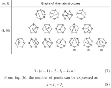
According to Eq.共9兲, the number of joints J can be solved for a given number of links n. Due to the number of joints is a posi-tive integer and the number of links is up to eight共R3兲, the num-ber of links and joints pair共n, j兲 can be solved as 共4, 4兲, 共6, 7兲, and 共8, 10兲. These three sets of numbers of links and joints can be used to search for kinematic structures. Mruthyunjaya and Raghavan 关7兴 enumerated kinematic structures with up to ten links, where one, two and sixteen kinematic structures are found for the num-ber of links and joints pairs共4, 4兲, 共6, 7兲, and 共8, 10兲, respectively. For the variable-stroke engine mechanism, since the number of independent loops is confined to three共Cr. 1兲, only the sixteen kinematic structures with eight links and ten joints fulfill this re-quirement. Table 3 shows graphs of these admissible kinematic structures.
5 Identification of Compatible Kinematic Structures
Since the admissible kinematic structures are obtained based on the structural requirements, they have to be carefully evaluated whether the functioning kinematic chain can be part of them. This indicates that kinematic structures, which comprise at least one segment with the same characteristics of the functioning kine-matic chain, are considered as compatible kinekine-matic structures. Hence, compatible kinematic structures can be identified, as long as there exists at least one path/circuit关3,6兴 with the same con-nectivity list and joint DOF list of the functioning kinematic chain. This segment of the kinematic structures for the functioning kinematic chain can be identified with the design constraints on locations of the functioning links.
For the variable-stroke engine mechanism, the sixteen admis-sible kinematic structures will be checked whether at least one path with the connectivity list and joint DOF list match with Eqs. 共3兲 and 共4兲 for the functioning kinematic chain of eight-link kine-matic structures. It can be seen that only those kinekine-matic struc-tures in the last row of Table 3 have a link with 4-connectivity and only the last six kinematic structures could comprise a path with the connectivity list of Eq.共3b兲. In this case, the check of the joint DOF list can be disregarded since all joints of the kinematic struc-tures in Table 3 are of 1-DOF and will fulfill Eq.共4兲 spontane-ously.
The criteria Cr. 1, Cr. 2, and Cr. 3 in Table 2共c兲 are used as a guide to further detect the location of paths for the functioning kinematic chain and identify compatible kinematic structures.
Fig. 3 Construction of the functioning kinematic chain
Table 3 Graphs of kinematic structures with up to eight links
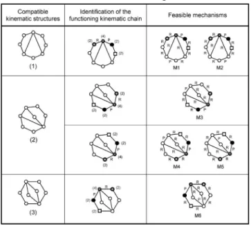
The second kinematic structure from the right in the last row of Table 3 is used as an example to illustrate how the functioning kinematic chain is identified in a kinematic structure as shown in Fig. 4共a兲. Locating the only one four-connectivity link as the ground link, it can be seen that only one of those two-connectivity links adjacent to the ground can be assigned as crank. However, from Cr. 2, the crank and piston shall be included in two separate loops and each belongs to its respective loops only. Hence, only link b can be selected as the piston for the case link a is assigned as the crank while link a can be selected as the piston for the case links b is assigned as the crank. The joint between the crank and ground is labeled as revolute joint and the joint between the piston and ground is labeled as prismatic joint. Accordingly, two paths with the connectivity list FC: 关2, 4, 2, 2兴 can be found for the
functioning kinematic chain as shown in Fig. 4共a兲. Note that the two ends of these two paths, namely the crank and connecting rod are not adjacent and, thus, fulfill Cr. 3. With this process, the kinematic structures No. 1–3 in Table 3 are found to contain at least one such nonisomorphic path for the functioning kinematic chain, as shown in Table 4. Hence, kinematic structures No. 1–3
are identified as compatible kinematic structures.
It can be seen that by assigning the functioning kinematic chain into the searched kinematic structures, the number of compatible kinematic structures is substantially reduced. As per the approach of Freudenstein and Maki关2兴, all kinematic structures that fulfill structural requirements need to proceed to a cumbersome proce-dure by assigning the ground link and labeling joint types to every mechanism, feasible or nonfeasible. For example, according to Freudenstein and Maki’s approach, hundreds of mechanisms can be enumerated 关13兴, if all the possibility for the eighteen kine-matic structures of Table 3 is explored. However, in this proposed methodology, only three of the eighteen kinematic structures are identified as compatible kinematic structure and, thus, the process on further implementation on joint labeling can be enormously simplified.
6 Labeling of Joint in Compatible Kinematic Structures
From the design constraints on the joints of the mechanism, limitations on the type, orientation, location, etc. of the joints are specified. Subject to these design constraints, unspecified joints of compatible kinematic structures are labeled to accomplish the enumeration of feasible mechanisms.
For the variable-stroke engine mechanism, all the compatible kinematic structures with identified functioning kinematic chain have ten joints, in which the joint between the ground link and piston and the joint between the ground link and crank have been labeled. The remaining eight joints are determined subject to D3,
D4, D5, and D6 of Table 2共c兲. The two kinematic structures with
identified functioning kinematic chain shown in Fig. 4共a兲 are used as an illustrative example, where the drive, output and control loop are further recognized in Fig. 4共b兲. From, D3, all unspecified joints adjacent to the prismatic joint P between the piston and ground are labeled as revolute joints R as shown in Fig. 4共b兲. By considering D4, unspecified joints in the drive loop are all labeled as R. In addition to the prismatic joint between the piston and ground, there should be another prismatic joint in the control loop to fulfill D5 and D6. As shown in Fig. 4共b兲, a feasible mechanism M3 is obtained by labeling the unspecified joint in the control loop as P and the other unspecified joints as R. Two feasible mechanisms M4 and M5 are obtained due to the two choices of unspecified joints in the control loop as P and the others as R. With this process, as shown in Table 4, feasible mechanisms M1
Fig. 4 „a… Identification of the functioning kinematic chain; „b… Labeling of unspecified joints
to M6 are enumerated based on the three compatible kinematic structures.
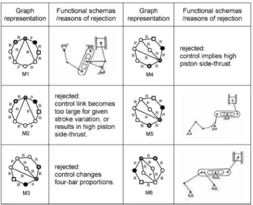
As per the study of Freudenstein and Maki关13兴, hundreds of enumerated kinematic structures are evaluated with functional re-quirements as well as other considerations from the experience of the designer. Three feasible mechanisms are obtained, i.e., M1, M5, and M6 shown in Table 5. It is found that mechanisms M2, M3, and M4 are considered infeasible in the study of Freudenstein and Maki关13兴 based mainly on subjective judgment. Functional schematic representation of the three feasible mechanisms M1, M5, and M6 and the reasons of Freudenstein and Maki关13兴 for rejecting M2, M3, and M4 are shown in Table 5.
7 Conclusion
In this paper, design specifications are classified as functional requirements, structural requirements, and design constraints. These different categories of design specifications are used to guide the construction of functioning kinematic chain, identifica-tion of compatible kinematic structures, and labeling of the joints in compatible kinematic structures. With this methodology, design specifications are well classified and systematically taken into ac-count during the conceptual design process. As a result, the enu-meration of feasible mechanisms is performed in a much more efficient manner. It is believed that this methodology can be ben-eficial for the design of mechanisms in the conceptual design stage.
References
关1兴 Ullman, D. G., 1992, The Mechanical Design Process, McGraw-Hill, New York.
关2兴 Freudenstein, F., and Maki, E. R., 1979, “The Creation of Mechanisms Ac-cording to Kinematic Structure and Function,” Environ. Plann. B, 6, pp. 375– 391.
关3兴 Buchsbaum, F., and Freudenstein, F., 1970, “Synthesis of Kinematic Structure of Geared Kinematic Chains and Other Mechanisms,” J. Mech., 5, pp. 357– 392.
关4兴 Mayourian, M., and Freudenstein, F., 1984, “Development of an Atlas of The Kinematic Structures of Mechanisms,” ASME J. Mech., Transm., Autom. Des., 106, pp. 458–461.
关5兴 Crossley, F. R. E., 1965, “The Permutations of Kinematic Chains of Eight Members or Less From the Graph-Theoretic Viewpoint,” Developments in
Theoretical and Applied Mechanics, Pergamon, Oxford, Vol. 2, pp. 467–486.
关6兴 Franke, R., 1958, Vom Aufbau der Getriebe, VDI Verlag, Dusseledrof, Vol I. 关7兴 Mruthyunjaya, T. S., and Raghavan, M. R., 1979, “Structural Analysis of
Ki-nematic Chains and Mechanisms Based on Matrix Representation,” ASME J. Mech. Des., 101, pp. 488–494.
关8兴 Mruthyunjaya, T. S., and Raghavan, M. R., 1984, “Computer-Aided Analysis of the Structure of Kinematic Chains,” Mech. Mach. Theory, 19, pp. 357–368. 关9兴 Mruthyunjaya, T. S., 1984, “A Computerized Methodology for Structural Syn-thesis of Kinematic Chains: Part 1-Formulation,” Mech. Mach. Theory, 19, pp. 487–495.
关10兴 Mruthyunjaya, T. S., 1984, “A Computerized Methodology for Structural Syn-thesis of Kinematic Chains: Part 2-Application to Several Fully or Partially Known Cases,” Mech. Mach. Theory, 19, pp. 497–505.
关11兴 Mruthyunjaya, T. S., 1984, “A Computerized Methodology for Structural Syn-thesis of Kinematic Chains: Part 3-Application to the New Case of 10-Link, Three-Freedom Chains,” Mech. Mach. Theory, 19, pp. 507–530.
关12兴 Davies, T. H., and Crossly, F. E., 1966, “Structural Analysis of Plane Linkages by Franke’s Condensed Notation,” J. Mech., 1, pp. 171–183.
关13兴 Freudenstein, F., and Maki, E. R., 1983, “Development of an Optimum Variable-Stroke Internal-Combustion Engine Mechanism From The Viewpoint of Kinematic Structure,” ASME J. Mech., Transm., Autom. Des., 105, pp. 259–267.
关14兴 Freudenstein, F., and Maki, E. R., 1984, “Kinematic Structure of Mechanisms for Fixed and Variable-Stroke Axial-Piston Reciprocating Machines,” ASME J. Mech., Transm., Autom. Des., 106, pp. 355–364.
关15兴 Datseris, P., and Palm, W., 1985, “Principles on the Development of Mechani-cal Hands Which Can Manipulate Objects by Means of Active Control,” ASME J. Mech., Transm., Autom. Des., 107, pp. 148–156.
关16兴 Erdman, A. G., and Bowen, J., 1981, “Type and Dimensional Synthesis of Casement Window Mechanism,” Mech. Eng.共Am. Soc. Mech. Eng.兲, 103, pp. 46–55.
关17兴 Yan, H. S., 1992, “A Methodology for Creative Mechanism Design,” Mech. Mach. Theory, 27, pp. 235–242.
关18兴 Tsai, L. W., 2000, Mechanism Design: Enumeration of Kinematic Structure
According to Function, CRC Press, New York.
关19兴 Belfoire, N. P., and Tsai, L. W., 1991, “A New Methodology for Structural Synthesis of Geared Robotic Wrists,” in Proceedings of the Second National
Conference on Applied Mechanisms and Robotics, Paper No. VIB. 5.
关20兴 Zhou, H., and Ting, K. L., 2005, “Topological Synthesis of Compliant Mecha-nisms Using Spanning Tree Theory,” ASME J. Mech. Des., 127, pp. 753–759. 关21兴 Pahl, G., and Beitz, W., 1999, Engineering Design: A Systematic Approach,
Springer Verlag, New York.
关22兴 Suh, N. P., 1990, The Principle of Design, Oxford University Press, Oxford. 关23兴 Reuleaux, F., 1876, Kinematics of Machinery, McMillan, London.
Table 5 Functional schemas of feasible variable-stroke engine mechanisms†13‡