Design and Implementation of a Voice-Coil Motor
Servo Control IC for Auto-Focus Mobile Camera
Applications
Jhih-Da Hsu
1, Ching-Lung Tsai
2, and Ying-Yu Tzou
1, Member, IEEE
1Power Electronics Systems & Chips Lab., Advanced Power Electronics Center, Department of Electrical and Control Engineering, National Chiao Tung University, Taiwan.
2VASSTEK International Corporation, Taiwan.
Abstract-This paper presents the design methodology to implement a fully digital control IC for the position control of the auto-focus (AF) lens module in applications to mobile phone camera using the field programmable gate array (FPGA). As compared with the conventional stepping motor control with a spring return fixture, the AF lens module is driven by a voice-coil motor (VCM) with a digital servo drive IC. The proposed digital servo drive IC includes a digital servo controller, a digital current controller, and a full-bridge dc-dc converter. The designed digital servo drive IC provides a total digital solution to the position control of the AF lens module in applications to high-performance light-weight slim-type mobile phone camera and video. The designed AF lens module can reach a control range of 0.6 mm within 30 ms with a control resolution less than 5 µm, a peak driving force of 30 mN, and a peak output current of 120 mA.
I. INTRODUCTION
In today’s marketing world of mobile camera, there are mainly three types of the actuator: stepper motors, piezoelectric materials and VCM with spring return. The stepper motors are easy to control and need no holding power after lens movement is complete, but the mechanical architecture is complex and thus their volume are relatively large. Using the piezoelectric materials as actuators needs no gears and the power consumption is low, but they are sensitive to temperature and the control laws are complex. The VCM has features of small volume, low cost, easily to be implemented and shock-resistant [1]. However, a spring is needed to implement the open loop position control and thus holding power is inevitable. The current that sinks is positive to the displacement, and can be up to 0 ~100 mA.
The design of VCM in this paper is composed of a set of permanent-magnetic circuit and coil. Its operation principle follows Lorentz force law. Instead of using spring-return method, the lens’ motion is under closed loop control. Thus the holding power is lowered and the ringing phenomenon does not exist. The volume of the lens module is 10mm
×
14mm×
13mm and the mass of the mover is 1 g.The proposed VCM servo control IC provides totally digital solution for fast auto focus mobile phone camera applications.
The driver stage uses a full-bridge converter as the power amplifier, and the switching frequency is 100 kHz. The DC link voltage is 3.3V and the maximum output current is 120 mA. The settling time is less than 30ms, thus it is capable of dealing with a shooting speed of 30 frames per second.
II. DYNAMIC MODEL OF THE LENS MODULE
The lens module is composed of three parts: a camera lens , a VCM and a pair of guide pin. The mathematical model of the module can be represented as follows:
(1)
(2)
where Kf is the force constant in N/A and equal to the back EMF constant in V-sec./m. Theoretically KF is related to the number of windings and the flux density in the air gap and is various with position. Fpin(po) represents the magnetic force between the guide pins and the mover along the moving direction. The guide pin force Fpin(po) can be extracted from electromagnetic simulation software. According to Ansoft’s Maxwell simulation, |Fpin(po)|max is about 15 mN at the ends of the guide pin and zero at the center of the full stroke. Mg is the weight of the camera lens, which should be taken into consideration while moving up and down. f( v, po) represents the standard Coulomb plus static plus viscous friction model [2]-[3]. Let iKF – Mg − Fpin( po) be Fu( po) and the stick region width be ±∆v, during stick, |v|<∆v :
(3a)
and during slip, |v|>∆v :
(3b)
where fc > 0 is Coulomb friction level, fs is the static friction force, and KB > 0 is the viscous friction coefficient. Extra current is needed when the lens module is beginning to move, and the Stribeck effect [4] causes low frequency stick-slip
This work was supported by VASSTEK International Corporation, Hsinchu, Taiwan, R.O.C. Project no. 95C025.
) , ( ) ( d d o o pin f Mg F p f v p t v M K i⋅ = + + + t i L R i K v vo e d d + ⋅ = ⋅ − ⋅ ≤ = ohterwise p F f f p F if p F p v f o u s s o u o u o )) ( sgn( | | ) ( ) ( ) , ( v K v f p v f( , o)= csgn( )+ B
.
.
limit cycle oscillation, thus the nonlinear effects arose from friction must be taken into consideration when designing the controllers.
As shown in Fig. 1, the physical system includes the lens module, a full bridge converter with switching frequency 100 kHz, a current sensing circuit, a position sensor and an anti-alias filter. A 200 kHz A/D converter is shared between the current feedback and position feedback. The digital controller is mainly composed of the three loops controllers: current-loop, velocity-loop, and position-loop controller. The second-order IIR filter is used to filter out the A/D conversion noise. The velocity estimator uses the second-order Taylor series expansion, which will be discussed later.
III. CURRENT LOOP DESIGN
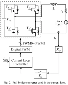
Fig. 2 shows the current driver is realized by a digital control loop, in which the driver stage is a full-bridge converter. The -bit digital pulse width modulator generates switch control signals by means of unipolar voltage switching. Compared with bipolar voltage switching, under the same switching frequency, unipolar has less output current ripple:
(4)
The main advantage in using a current driver is that the current through the VCM is insensitive of variations in winding impedance and back EMF. The back EMF can be viewed as a disturbance in the current loop. The transfer function Gc (s) from vo to io can be represented as:
(5)
In this application, the VCM has small inductance and relatively large equivalent series resistance (ESR), thus
(6)
The transfer function Gc (s) can be reduced to
(7)
In order to improve dynamic response, the bandwidth of current loop can be extended with pole-zero cancellation to speed up the response time. Thus a PI controller is applied and the current-loop bandwidth is decided by the controller gain. Let the current-loop control low is designed as ( ) 2nd order IIR Filter L r Ls+ 1 f K s 1 + - Ms 1 Fpin + + f ( v, po) Mg + + PWM K cf K + -e K 2 s T pf K lv K Velocity Estimator + - + -+ 1 1− z− Kic pc K + + pcmd po io vo icmd vcmd Anti-alias Filter v Back EMF non-linear position loop gain 2 s T 1 s T
Digital Controller Physical System and Feedback Filter
Fi 1. Block diagram of the proposed digital control scheme.
Vdc TA+ TA -TB+ TB -L rL Back EMF Digital PWM Current Loop Controller cf K 2 s T PWM0~ PWM3 +-icmd if
Fig. 2. Full-bridge converter used in the current loop.
. L c r Ls s G + ≈ 1 ) ( ] 1 [ ] 1 [ ] [ ) ( ) (k = K +K i k +K i k− +v k− vc ic pc e pce c L DT D V iL= d(1− ) s/2 ∆ 2 2 ) ( e L c K Ms r MLs Ms s G + + = M K L rL e 2 2 4 >> ] [ ] [ ] [k i k K i k ie = c − cf⋅ L
(9)
(10)
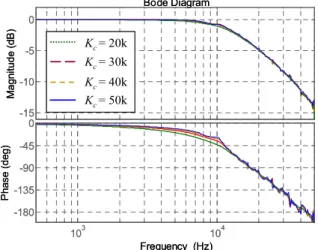
where fsc is the sampling frequency of the current-loop controller and Kc is the controller gain that decides current-loop bandwidth. However, the switching frequency of the full-bridge converter is 100 kHz, according to sampling theorem, the current-loop bandwidth can not lager than 50 kHz. Fig. 3 shows that with 200 kHz A/D converter sampling rate and 100 kHz switching frequency is considered, rising Kc from 30 k to 50 k has less effect on increasing current-loop bandwidth. Instead, too large the current loop gain Kc introduces high frequency oscillation.On the other hand, with unipolar switching, the dead time between the upper and bottom transistor has large effect on the performance of current loop. The effect is evaluated by total harmonic
distortion (THD), which is defined as
(11)
where I1 is the RMS value of the fundamental current and In is the n-th harmonic. The effect of dead time on the THD is shown in Fig. 4 where Dt represents its percentage ratio.
The input current command is 20% of the maximum current and the fundamental frequency is 5 kHz. For Dt = 2% is concerned, increasing the current-loop gain can reduce the dead time effect, that is, lower the THD. However, when fc is larger than 25 kHz, increasing fc has little influence on reducing the THD, thus for THD improvement and stability consideration, the current-loop bandwidth is designed between 20 kHz to 25 kHz that provides good tacking ability for 5 kHz current command.
IV. SERVO LOOP DESIGN
A. Velocity Loop
Since the position signal is present in the digital controller, a numerical method is used to estimate the motor speed. The velocity estimator is implemented using the second-order Taylor series expansion [5]:
(12)
where is the estimated velocity during k-th period, ∆xk and ∆xk-1 represent measured position change during k-th and (k-1)-th sampling interval. As Fig. 5 is shown, Kpf is the position sensor gain. The velocity feedback acts at the transient of the position response and rests when the lens module is in position. The velocity controller gain Klv is decided by
(13)
where ωcv is the velocity-loop bandwidth. However, increase of Klv may introduce audible noise at the transient of position response. Based on the experiments, ωcv is designed at 1 kHz. The sampling rate of the velocity loop is selected at 20 times of the velocity loop bandwidth, thus the phase lag contributes by sampling delay can be ignored. Since the current-loop bandwidth is designed at 10 kHz, the current loop can be viewed as a DC gain 1/Kcf while designing the velocity loop, where Kcf is the feedback gain of the current loop.
-15 -10 -5 0 Ma gni tu d e (dB ) 103 104 -180 -135 -90 -45 0 P has e (d eg) Bode Diagram Frequency (Hz) Kc= 50k Kc= 20k Kc= 30k Kc= 40k -15 -10 -5 0 Ma gni tu d e (dB ) 103 104 -180 -135 -90 -45 0 P has e (d eg) Bode Diagram Frequency (Hz) Kc= 50k Kc= 20k Kc= 30k Kc= 40k Kc= 50k Kc= 20k Kc= 30k Kc= 40k
Fig. 3. Frequency response of the current loop with different controller gain Kc. 5% 6% 7% % 9% 10% 11% 12% 13% 14% 15% 16% 17% 1 % 19% 20% 21% 22% 23% 24% 25%
5.0E+03 1.0E+04 1.5E+04 2.0E+04 2.5E+04 3.0E+04 3.5E+04 4.0E+04 4.5E+04 5.0E+04 fc(Hz )
THD Dt = 0% Dt = 1% Dt = 2% Dt = 3% Dt = 4%
Fig. 4. Simulation results of fc versus THD with dead time.
cf K 1 3 s T pf K lv K Velocity Estimator Ts3 ZOH s 1 -vcmd + po current loop Ms 1 f K + + force disturbances
Fig. 5. Block diagram of the velocity loop.
cf PWM c pc K K L K K = 2π cf PWM sc L c ic K K f r K K = 2π )] ( 2 / 1 [ ˆk=KD ∆xk+ ∆xk−∆xk−1 v k vˆ M K K K K K cf D pf f cv lv ω = 2 1 1 ) ( 100 THD %
∑
≠ × = n n I IB. Position Loop
Fig. 6 shows that the position controller is a look-up table that has higher gain when the position error is small and lower gain when the position error is large. The output of the controller is velocity command which is defined as
(14)
where ∆Kp = Kp1 - Kp2, Kp1 and Kp2 are the controller gain of different region of the position error defined by ε. Appling higher gain at low position error makes the system generate larger current command to overcome the force disturbances such as the weight of the lens Mg, guide pin magnetic force Fpin(po) and static friction fs when the VCM is beginning to move. The higher gain Kp1 also reduces position steady state error since no integrator is present in the servo loop controller. The reason that not using an integrator is to prevent the system suffers from stick-slip oscillation. The steady state position error produced from Mg and Fpin(po) is
(15)
where Imax is the maximum motor current and Pmax is the full stroke of the lens module. It can be seen that the parameters Pmax, Imax and Kf are fixed by motor specification, and Klv is restricted by audible noise consideration, thus Kp1 is the major parameter designed to reduce steady state position error. However, rising Kp1 may introduce system oscillation, thus Kp2 is designed to make the position response have more following error to prevent system from oscillation. The following error eflv under this variable position loop gain is
(16)
where efl1 and efl2 are the following error under constant position loop gain Kp1 and Kp2, respectively. Thus ε can be decided by the specified eflv.
V. HARDWARE REALIZATION AND EXPERIMENTAL RESULTS
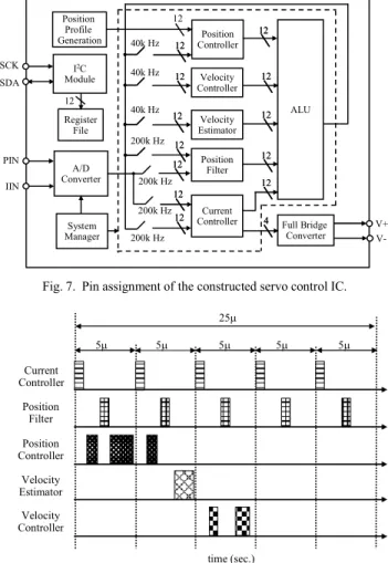
Fig. 7 shows the interface and functional block diagram of the constructed servo control IC for the VCM lens module. This IC allows user to set the controller parameter according to the load (camera lens) and response time. All modules including current controller, position filter, position controller, velocity estimator and velocity controller share the same ALU unit by time-sharing scheme for arithmetic operation. The time-sharing scheme is mixed with 40 kHz and 200 kHz sampling frequency as shown in Fig. .
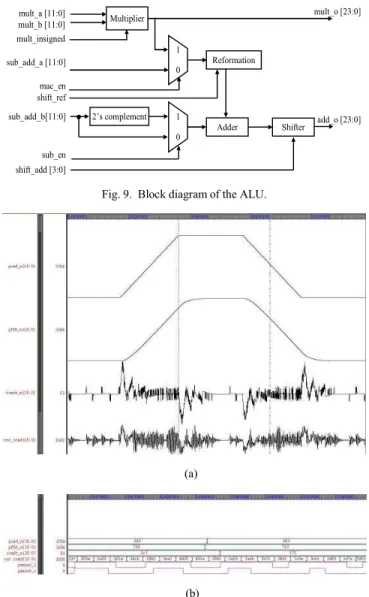
Fig. 9 shows the detail block diagram of the ALU unit, which supports both of add, minus and single cycle operation for arithmetic operation a×b+c.
The validation of the ASIC implementation is simulated by NCVerilog. Fig. 10(a) shows the simulation result of position and current response. The VCM is in position in 15 ms and no stick-slip limit cycle oscillation occurs. Unipolar voltage switching scheme is applied to the full-bridge converter. The last two rows of wave form in Fig. 10(b) are the PWM signal of the two upper transistors respectively. It shows that the switches work as desired.
D pfK K 1 3 s T pf K 3 s T ZOH s 1 -pcmd + po velocity loop look-up table
Fig. 6. Block diagram of the position loop.
A/D Converter Position Controller Velocity Controller Current Controller Position Filter Velocity Estimator ALU System Manager Position Profile Generation 40k Hz 40k Hz 40k Hz 200k Hz 200k Hz 200k Hz 12 12 12 12 12 12 12 12 12 12 12 12 12 12 12 12 12 4 4 12 12 12 12 Full Bridge Converter 12 12 Register File I2C Module 12 PIN IIN SCK SDA V+ V-12 12 200k Hz
Fig. 7. Pin assignment of the constructed servo control IC.
Current Controller Position Filter Position Controller Velocity Estimator Velocity Controller 5µ 25µ 5µ 5µ 5µ 5µ time (sec.)
Fig. . Timing analysis of the ALU sharing effort.
− < ∆ ⋅ − ⋅ < ∆ ⋅ + ⋅ ≤ ⋅ = ε ε ε ε ε err p err p err p err p err err p cmd p if K p K p if K p K p if p K v 2 2 1 f lv p o pin ess K K K I p F Mg P p 1 max max 2 ) ( + = ) ( 2 1 1 2 fl fl fl fl flv e e e e e = − ε −
Fig. 11 illustrates the hardware architecture of the experimental system constructed in this paper. The developed servo control IC works as a coprocessor with a single-chip MCU (AT 9C51RD2) from ATMEL. The MCU serves as a host processor and governs the work of tuning control parameters. The developed servo control IC receives sensed position signal and inductor current from the lens module. The feedback signals are multiplexed before feeding into the 12-bit AD converter. The position sensor maps the physical position 0-0.6 mm to 1.2-2.5 V, and the motor current is between ̈́120 mA. The converted digital data is then sent to FPGA for further processing.
Fig. 12 illustrates the position responses to ramping commands of back-and-forth of the designed digital servo drive IC with the VCM for auto-focusing module. The traverse distance is 0.5 mm with a feed rate of 16.7 µm/ms and can achieve a position control resolution of 5 µm. Experimental results verify the designed digital servo drive IC can meet the design specifications of an auto-focus module used for high-performance slim-type digital camera applications. Multiplier 1 0 Reformation Adder Shifter 2’s complement 1 0 mult_a [11:0] mult_b [11:0] mult_insigned mult_o [23:0] add_o [23:0] sub_add_a [11:0] mac_en shift_ref sub_add_b[11:0] sub_en shift_add [3:0]
Fig. 9. Block diagram of the ALU.
(a)
(b)
Fig. 10. Simulation results of the developed servo control IC. (a) Position and current response. (b) PWM signal of the two upper transistors.
Control IC MCU VCM with a Camera Lens and a Position Sensor ADIN SCK SDA V+ V-SCK SDA
sensed position signal sensed inductor current
EEPROM DONE CCLK DIN ADC CONVST Mux 12 RS232
Fig. 11. Hardware architecture of the experimental setting.
psn isn (a) psn isn (b)
Fig. 12. Experimental results of the position and current response. (a) The lens module moves from top to bottom; (b) The lens module moves from
VI. CONCLUSION
In this paper, an FPGA-based servo control IC for the closed-loop control of VCM used in an auto-focus module of a mobile phone is developed. This paper also proposed a fully digital cascaded loops control scheme. The inner current loop reduces disturbances such as change of electrical impedance and back EMF. Also, the dead time effect is reduced and the current waveform distortion can be lowered by increasing the current loop gain. The velocity loop compensates the mechanical pole and fastens position response. The outer position loop is designed to meat the specifications such as response time and steady-state error. In the hardware realization, by using time-sharing scheme, the ALU is shared to each component of the controller to save resources. The simulation and experimental results show that the position response time meats the specification and no stick-slip limit cycle oscillation occur, thus the solution is realizable.
REFERENCES
[1] Sung-Min Sohn, Sung-Hyun Yang, Sang-Wook Kim, Kug-Hyun Baek, and Woo-Hyun Paik, “Soc Design of An Auto-Focus Driving Image Signal Processor for Mobile Camera Applications ,” IEEE Trans. Consumer Electronics, vol. 52, Issue 1, pp. 10-16, Feb., 2006.
[2] Craig T. Johnson and Robert D. Lorenz, “Experimental identification of friction and its compensation in precise, position controlled mechanisms,” IEEE Trans. Industry Applications, vol. 2 , Issue 6, pp. 1392–139 , Nov./Dec. 1992.
[3] Liyu Cao and H. M. Schwartz, “Stick-slip friction compensation for PID position control,” American Control Conference, vol. 2, pp. 107 – 10 2, June 2000.
[4] George Ellis, Control System Design Guide, 2nd ed., Academic Press, pp.
234-237, 2000.
[5] Xiaoyin Shao and Dong Sun, “Development of an FPGA-Based Motion Control ASIC for Robotic Manipulators,” Intelligent Control and Automation, vol. 2, pp. 221- 225, June 2006.