Conjugated Polymer/Nanocrystal Nanocomposites for
Renewable Energy Applications in Photovoltaics and
Photocatalysis
Yu-Wei Su , Wei-Hao Lin , Yung-Jung Hsu , and Kung-Hwa Wei *
C
onjugated polymer/nanocrystal composites have attracted much
attention for use in renewable energy applications because of
their versatile and synergistic optical and electronic properties.
Upon absorbing photons, charge separation occurs in the
nanocrystals, generating electrons and holes for photocurrent fl ow
or reduction/oxidation (redox) reactions under proper conditions.
Incorporating these nanocrystals into conjugated polymers can
complement the visible light absorption range of the polymers for
photovoltaics applications or allow the polymers to sensitize or
immobilize the nanocrystals for photocatalysis. Here, the current
developments of conjugated polymer/nanocrystal nanocomposites
for bulk heterojunction–type photovoltaics incorporating Cd- and
Pb-based nanocrystals or quantum dots are reviewed. The effects
of manipulating the organic ligands and the concentration of the
nanocrystal precursor, critical factors that affect the shape and
aggregation of the nanocrystals, are also discussed. In the conclusion,
the mechanisms through which conjugated polymers can sensitize
semiconductor nanocrystals (TiO
2, ZnO) to ensure effi cient charge
separation, as well as how they can support immobilized nanocrystals
for use in photocatalysis, are addressed.
1. Introduction ... 4428
2. Photovoltaics Application ... 4429
3. Photocatalysis Applications ... 4434
4. Conclusion ... 4438
1. Introduction
Semiconductor nanocrystals exhibiting quantum confi nement properties, so-called “quantum dots” (QDs), are emerging as functional materials for applications in light harvesting and photocatalysis because of their size-tunable band gaps and large surface-to-volume ratios that allow them to interact with other materials (e.g., polymers). In order to produce size-tunable band gaps, the size range of nanocrystal QDs must be comparable to or smaller than the Bohr exciton radius—the size of exciton (a pair of bonded electron and hole) in bulk semiconductors. This feature of nanocrystal QDs restricts carrier (electrons and holes) motion in all three spatial dimensions. As the size decreases, the electronic exci-tations shift to higher energy and results in a higher band gap energy ( E g ). Upon absorbing light, an electron is excited from
the valence band to the conduction band of the QD; when these QDs form heterojunctions with off-set energy band structures with conjugated polymers, the excitons can readily dissociate into free charge carriers. These photo-induced and dissociated charge carriers can then migrate to their respective electrodes (allowing photovoltaics applications) or diffuse to the nanocrystal surface to mediate reduction/ oxidation (redox) reactions (allowing photocatalytic applica-tions). Incorporating nanocrystals into conjugated polymers can not only facilitate photovoltaics device fabrication on fl exible substrates and the use of wet-processing techniques (e.g., roll-to-roll coating or printing) [ 1 ] but also provide the
possibility to have a large interfacial area for effi cient exciton dissociation. [ 2 ] In this Article, we review the conjugated
pol-ymer/nanocrystals composites that have been used for photo-voltaics and photocatalysis applications.
Traditional silicon and thin fi lm photovoltaics harvest only approximately 33% of the energy from any given solar photons; another 33% is lost to thermalization, with the remaining 34% being energy that is not absorbed or unavoid-able thermodynamic losses. [ 3 ] The use of nanocrystal QDs in
photovoltaics can lead to a higher limiting conversion effi -ciency through either recovery of some energy lost through thermalization or providing pathways to harvest those pho-tons not absorbed in a tradition solar cell. [ 4 ] Chalcogenide
(PbX, CdX; X = S, Se, Te) nanocrystal QDs have attracted attention for use in solar cells because of the potential for multiple exciton generation (MEG), also known as the impact ionization process. [ 5–7 ] In the impact ionization
pro-cess, a high-energy exciton, created by absorbing a photon of energy that is much larger than the band gap of the QDs (>=2 E g), relaxes to the band edge and transfers energy to
another electron in the valence band to overcome the band gap energy required to transfer its excited electron to the conduction band; therefore, this process has the potential to generate more than one electron/hole pair after the absorp-tion of a single photon, thereby increasing the photocurrent, and thus, the power conversion effi ciency (PCE) of the pho-tovoltaic device. The effect of MEG of the QDs on conju-gated polymer/QDs nanocomposite was found to be able to enhance external quantum effi ciency (EQE) up to 150% at negative biases, [ 8 ] but no other studies on this phenomenon
has been reported. For conjugated polymers to be used in DOI: 10.1002/smll.201401508
Dr. Y.-W. Su, W.-H. Lin, Prof. Y.-J. Hsu, Prof. K.-H. Wei Department of Materials Science and Engineering National Chiao Tung University
Hsinchu 30010 , Taiwan E-mail: [email protected]
organic photovoltaics, they should ideally possess i) low band gaps, to broaden the absorption range; ii) crystalline charac-teristics, to ensure good charge mobility; and iii) suitably low energy levels for their highest occupied molecular orbitals (HOMOs), to enhance the open-circuit voltages ( V oc ) of their
devices. In reality, polymers having low band gaps generally require large conjugated structures, which sometimes are dif-fi cult to synthesize and to dissolve, and they often are not capable of effi ciently converting absorbed photons, from the infrared region, into electrons. These problems can be over-come by incorporating QDs possessing tunable band gaps, allowing light absorption by these QDs to complement that of the conjugated polymers, resulting in nanocomposites that can extend the absorption range further into the infrared region. Many reports have appeared regarding the devel-opment of ligands to improve the dispersion and electronic structure of nanocrystal QDs, [ 9 ] the construction of polymer/
nanocrystal nanocomposite solar cells, [ 3,10–14 ] and the analysis
of charge transfer (CT) kinetics. [ 15 ]
Photocatalysis is a green technique that has been applied widely in the fi elds of environmental remediation, antibacte-rial treatment, selective organic transformations, and solar water splitting. To effectively drive desired redox reactions mediated by photoinduced charge carriers, a semiconductor nanocrystal must have a suitable band gap energy with appro-priate energy levels for their conduction bands (analogous to the lowest unoccupied molecular orbital (LUMO) in an organic molecule) and valence band (analogous to the highest occupied molecular orbital (HOMO)). Overall, water splitting requires the bottom level of the conduction band to be more negative than the redox potential of H + /H
2 (0 V vs NHE),
while the top level of the valence band should be more positive than the redox potential of H 2 O/O 2 (1.23 V vs NHE). [ 16 ] Thus,
the minimum value of E g of a semiconductor nanocrystal for
water splitting should be 1.23 eV, but preferably greater than 2.0 eV in a practical setting to overcome energy losses caused by the kinetic overpotentials. Several issues in semiconductor nanocrystal photocatalysis remain unsolved: i) the photocata-lytic effi ciency of semiconductor nanocrystals is commonly suppressed by the inherently fast recombination of charge carriers; ii) most semiconductor photocatalysts currently available (e.g., TiO 2 , ZnO) can function in the UV or near-UV
region, and some approaches have been adopted to impart them with visible absorption, for instance the utilization of plasmonic effect from gold nanocrystal on TiO 2 ; [ 17–19 ] iii)
most semiconductor photocatalysts are prepared in powder form and are prone to forming aggregates during photo-catalysis processes. In recent years, nanocomposite photocata-lysts comprising semiconductor nanocrystals and conducting polymers have demonstrated remarkable photocatalytic prop-erties, promoting effective charge separation to increase the
carrier utilization effi ciency along with simple removal from reaction solutions. Their conducting polymers serve as photo-sensitizers for the semiconductor nanocrystals, allowing them to produce additional charge carriers and improve the photo-catalytic performance; in addition, the polymers serve as host materials that immobilize the semiconductor nano crystals, thereby improving the stability of the photocatalysts and maintaining the photocatalytic activity. [ 20–22 ]
2. Photovoltaics Application
Figure 1 presents the energy diagram of a bulk heterojunc-tion (BHJ) solar cell. The photon-to-electron conversion mechanism involves four fundamental steps. In the fi rst step, the absorption of light causes photoinduced excitation of an electron in the donor from the HOMO to the LUMO, forming a Frenkel exciton [i.e., a coulombically bound elec-tron (e − ) and hole (h + )]. The excitons in organic materials
have binding energies in the range from 0.5 to 1 eV; [ 23 ]
because these values are much higher than thermal energy ( kT = 0.025 eV) at room temperature (298 K), a second material—an electron acceptor—must be present to ensure a built-in internal fi eld at the interface, thereby dissociating any excitons into their free carriers. Nanocrystals (n-type materials) can, for example, be used as acceptor materials to replace the fullerene units while polymers remain as the donor materials in polymer/fullerene–based solar cells [ 24,25 ]
to form donor–acceptor (D–A) interfaces. In the second step, the excitons diffuse to the D–A interfaces within the diffu-sion length to prevent recombination for releasing photon energy and returning to the ground state. In the third step, an exciton at a D–A interface undergoes ultra-rapid CT to form a CT exciton with the hole and electron remaining in the D and A phases, respectively, held together through cou-lombic attraction. In the fourth step, the built-in electric fi eld causes the CT excitons to dissociate into free holes and elec-trons, which then travel through the D and A phases to their respective electrodes. These four steps in the photon-to-elec-tron conversion process are characterized by four conver-sion effi ciencies: the absorption effi ciency ( η A ), the exciton
diffusion effi ciency ( η ED), the charge separation effi ciency ( η CS ), and the charge collection effi ciency ( η CC ), respectively.
The EQE is defi ned, in terms of energy, as the ratio between the number of collected photogenerated charges at the elec-trodes and the number of incident of photons at a particular wavelength ( λ ); it can be expressed as
EQE( ) =λ η λ ηA( )× ED( )λ η× CS( )λ η× CC( )λ (1)
The PCE (%), of a photovoltaic device is defi ned as
PCE = (Jsc×Voc×FF) / (Pin) (2)
where J sc is the short-circuit current density, V oc is the
open-circuit voltage, FF is the fi ll factor, and P in is the power of the incident light. Equation ( 3) can be used to provide a theo-retical value of J sc for comparison with the value obtained
experimentally from the current density–voltage ( J – V ) measurements:
Yu-Wei Su received his M.S. and Ph.D. degrees from the School of Chemical, Biological & Environmental Engineering, Oregon Strate University in 2007 and 2011, respectively. He joined Prof. Kung-Hwa Wei's group in National Chiao Tung University as a postdoctoral fellow since 2012. His research interests include inorganic, organic photovol-taics and using small angle X-ray scattering for polymer structure.
Yung-Jung Hsu is an Associate Professor in the Department of Materials Science and Engineering, National Chiao Tung University, Taiwan. He received his Ph.D. degree in Chemical Engineering from National Tsing Hua University, Taiwan, in 2005. After his postdoctoral fellow working at National Ts-ing Hua University, he joined National Chiao Tung University and started the indepen-dent research career in 2007. His research interests include preparation of semicon-ductor nanoheterostructures, investigation of interfacial charge carrier dynamics, and development of advanced nanomaterials for photoconversion applications.
Kung-Hwa Wei is a distinguished Professor in the Department of Materials Science and Engineering, National Chiao Tung Univer-sity, Taiwan. He received his Ph.D. degree in Chemical Engineering from University of Massachusetts, Amherst, in 1987, and then worked at Wright-Patterson Air Force base and General Electric company before joining the University in 1993. His research interests include conjugated polymers, col-loidal quantum dots and metal nanoparticles nanocomposites, and graphene for photovol-taics, bio-sensing, electronic, and nonvolatile memory applications.
Figure 1. Fundamental mechanism of the photon-to-electron conversion process in BHJ solar cells. Reproduced with permission. [ 24 ] Copyright 2012, Elsevier Ltd.
( )EQE( ) d sc sun J hc q P
∫
λ λ λ λ = (3)where P sun ( λ ) represents the power of
photons at each wavelength of the solar spectrum. q is the elementary charge, h is Planck's constant, and c is the speed of light.
When inorganic nanocrystals are used as electron acceptors in a BHJ solar cell, they must have an electron affi nity higher than that of the donor polymers to ensure effi cient exciton dissociation and CT at the interfaces. Replacing the fullerene units with nanocrystals should have
sev-eral benefi ts: [ 14 ] i) the light absorption contribution of
chal-cogenide QDs is greater than that of fullerene derivatives, leading to enhanced photogeneration of charge carriers; ii) the light absorption of nanocrystals can be tuned to cover a broad spectral range through modifi cations of the sizes and shapes; iii) nanocrystals provide ultrafast and effi cient pho-toinduced charge carrier transfer between D and A materials; iv) nanocrystals have relatively high electron mobilities and good photostability and chemical stability. Despite all these benefi ts, the capping ligands on the QDs play an important role in their interface properties that determine the extent of mixing with the conjugated polymers as well as the carrier transport in these nanocomposites.
2.1. Preparation and Morphology of Polymer/Nanocrystal QDs
Colloidal CdSe QDs are typically synthesized through thermal decomposition (280–300 °C) of an organometallic Cd precursor with a Se precursor in a hot solution of hexylphos-phonic acid, trioctylphosphine oxide (TOPO), tributyl- or trioctylphosphine (TOP), or hexadecylamine (HDA). When the reaction is complete, the solution is suddenly cooled to room temperature to quench any further nucleation; it is then added into methanol to precipitate the nanocrystal CdSe QDs. After washing to remove any excess capping ligands, monodisperse nanocrystal QDs are obtained; their size and
shape can be controlled by the reaction time and the ratio of surfactants, injection volume and the monomer concen-tration, respectively. [ 26,27 ] Figure 2 displays the
photolumi-nescence (PL) spectra of CdSe nanocrystals synthesized in TOPO and in a TOPO/HDA mixture. Upon increasing the reaction time, pure TOPO as solvent resulted in a nearly linear increase in the emission line widths, whereas the mixed solvent led to constant emission line widths. [ 28 ]
Figure 3 a displays transmission electron microscopy (TEM) images of CdSe QDs stabilized with TOP and oleic acid (OA) (both pristine and washed), pyridine, and dithiol molecules. The pristine TOP/OA–capped QDs exhibited a regular hexagonal arrangement with the largest averaged interparticle distance of 7.7 nm between the QD centers. An additional ligand exchange process with 1,4-benzenedithiol (dithiol) decreased the distance to 5.5 nm. Figure 3 b pre-sents PL spectra for the CdSe QDs coated with TOP and OA (both pristine and washed), pyridine, and dithiol molecules. The relative intensity of the fi rst excitonic peak at 640 nm followed the sequence pristine > washed > pyridine-coated QDs; this peak was not observable for the dithiol-coated QDs. Pyridine ligand exchange provided an even higher number of trap states, enabling a decrease in radiative recom-bination as a result of the stabilized electrons in the π rings of the pyridine units. Exchange with dithiol decreased the PL signal intensity to almost zero, indicating that quenched radiative recombination arose from trapped holes in the lone pairs of sulfur atoms, which forms covalent bonds with cad-mium atoms. [ 29 ]
Figure 4 presents TEM images of blends of poly(2-methoxy,5-(2-ethyl)-hexyloxy- p -phenylenevinylene) (MEH-PPV) with pyridine-treated CdSe or TOPO-coated CdSe, with various weight percentages of the nanocrystals. The pyridine-treated CdSe nanocrystals aggregated together to form regions of densely packed nanocrystals surrounded by regions of polymer. As the concentration of nanocrystals increased, more nanocrystals aggregated to form a larger domain and a connected network in the plane of the fi lm. In contrast, the TOPO-coated CdSe nanocrystals underwent almost no aggregation at low concentration, because TOPO and MEH-PPV both have nonpolar faces. This morphology provides a rationale for why, in subsequent studies, solar cells required a suffi ciently high weight percentage of nanocrystals (>80%) to ensure effi cient quenching of the PL. [ 30 ]
Figure 3. a) TEM images and b) PL measurement of CdSe QDs presenting various surfactants. Reproduced with permission. [ 29 ] Copyright 2012, American Chemical Society.
Figure 2. Evolution of the PL spectra during the synthesis of CdSe nanocrystals in a) TOPO and b) TOPO/HDA (molar ratio: 1:4). Reproduced with permission. [ 28 ] Copyright 2002, American Chemical Society.
In 1992, fullerene (C 60 or C 70 )-doped polymers were reported to exhibit pho-toconductivity; [ 31 ] subsequent studies
revealed that photocurrents could be achieved when using semiconductor nanocrystals to photosensitize needlelike C 60 crystals. [ 32 ] A cluster shell comprising
CdSe QDs surrounded by functionalized C 60 molecules exhibited a superior pho-tocurrent response, with ultrafast electron transfer between the CdSe QD and the functionalized fullerene. [ 33,34 ] An
alterna-tive method was developed for the in situ generation of CdSe QDs in a polymer nanocomposite fi lm through thermal decomposition of a complex cadmium pre-cursor blended with the polymer. [ 35 ]
2.2. Cadmium-Based Nanocrystals
Figure 5 presents the chemical structures of some representative polymers that have been applied in the solar cells based on polymer/nanocrystal nanocomposites that are discussed in this Review. Poly-(3-hex-ylthiophene) (P3HT) as an electron-donor material has been attractive for forming P3HT/CdX (X = S, Se) BHJ solar cells
because it allows effective hole transport in its regioregular form. Table 1 lists all reported device characterization data for nanocomposite solar cells incorporating polymer/Cd-based nanocrystal blends. The size and concentration of the CdSe nanorods in the P3HT/CdSe blend solution can be tuned to control the degree of nanocrystal aggregation and to obtain high EQEs (>54%) and PCEs (ca. 2%). [ 36,37 ] In
addi-tion, the incorporation of three-dimensional hyperbranched CdSe nanocrystals into solution blends produces an active layer having large and distributed surface area for charge separation. [ 38 ] Other parameters, including the nature of the
solvent, [ 39 ] the annealing temperature, the annealing time, [ 40 ]
the nanocrystal size, [ 41 ] and the nature of the ligand on
CdSe, [ 42,43 ] have also been studied intensively to optimize the
device fabrication process. A modifi ed device architecture featuring ZnO nanoparticles as a buffer layer between the active layer (P3HT/CdSe) and the metal electrode (Al) has been demonstrated that the stability of the device enhanced to 60–70% of the original PCE after exposed to ambient condition for 70 days, as compared to a few hours life time without the ZnO layer. [ 44 ]
Recently, a chemical grafting approach was developed to bind CdS QDs onto P3HT nanowires, [ 45 ] allowing control over
organic/inorganic phase separation and signifi cantly improving the PCE to 4.1% from 0.6% for the approach without chem-ical grafting. A post-treatment process—immersing the sub-strate with the polymer/CdSe blend fi lm into an acetonitrile solution containing 1% ethanedithiol (EDT)—was used to remove the charged phosphonic acid ligands from the sur-faces of the CdSe nanorods and form monolayer-passivated
Figure 4. TEM images of blends of MEH-PPV with pyridine-treated CdSe and TOPO-coated CdSe at nanocrystal concentrations of 5, 20, and 65% (w/w). Reproduce with permission. [ 30 ] Copyright 1996, American Physical Society.
Figure 5. Chemical structures of representative polymers that have been incorporated in the solar cells based on polymer/nanocrystal nanocomposites that are discussed in this Review.
Cd-thiolate nanorods. Such EDT treatment decreased exciton and charge carrier recombination and increased charge trans-port in the polymer/CdSe hybrid fi lm, resulting in an increase in PCE to 2.9% from 2.2%. [ 46 ] A comparative study indicated
that a major fraction of the successfully separated charge car-riers in the P3HT/CdSe blends were trapped in deep localized states, whereas the geminate recombination resulted from only shallow traps in P3HT/fullerene blends. [ 47 ]
Low band gap conjugated polymers have also been studied for organic/inorganic hybrid photovoltaic applications. Before P3HT was used as an electron-donor material,
MEH-PPV [ 30 ] had been blended with CdSe and CdS nanocrystals for
use in solar cell devices. The absorption intensity in the vis-ible light range (600–650 nm) increases with the weight per-centage of CdSe in MEH-PPV/CdSe blends; the PCE reached to 0.2% under AM 1.5 conditions at an incident energy of 0.5 mW cm −2 when 90 wt% CdSe was incorporated. Figure 6 presents three possible routes for exciton separation and CT in MEH-PPV/CdSe blends. Excitons created in MEH-PPV can experience charge separation through electrons transferring from the polymer to the nanocrystal (route a). Alternatively, if the exciton is created on the nanocrystal (route c), or trans-fers onto the nanocrystal (route b), the hole can subsequently transfer to the polymer, producing a separated state of an electron on the nanocrystal. If CdSe nanocrystals are replaced by CdS nanocrystals, the excitons generated in the polymer are unable to transfer to the nanocrystals, because the band gap of CdS is larger than that of the polymer. [ 30 ] Photoinduced
absorption spectroscopy has been used to observe long-lived positive polarons in MEH-PPV/CdSe blends following elec-tron transfer to the nanocrystals. [ 48 ] Many subsequent studies
have focused on using polymer/CdSe nanocrystal systems to
keep improving device performance. Polymer derivatives fea-turing modifi ed side chains, including poly(2-methoxy-5-(3 ′,7′-dimethyloctyloxy)- p -phenylenevinylene) (MDMO-PPV) [ 49,50 ]
and poly(triphenylamine acrylate) (PTPAA) [ 51 ] can improve
Figure 6. Routes for exciton transfer and CT in MEH-PPV/CdSe blends. a) Exciton created in the polymer after absorption, followed by electron transfer onto the nanocrystal. b) Exciton created in the polymer after absorption, followed by exciton transfer onto the nanocrystal, followed by hole transfer onto the polymer. c) Exciton created in the polymer after absorption in the nanocrystal, followed by hole transfer onto the polymer. Reproduced with permission. [ 30 ] Copyright 1996, American Physical Society.
Table 1. Device characterization data for nanocomposite solar cells incorporating polymer/Cd–based QD blends.
Ref. Polymer QD V oc [V] J SC [mA cm −2 ] FF PCE [%] Huynh[ 37 ] P3HT CdSe 0.70 5.7 0.40 1.7 Sun a)[ 39 ] P3HT CdSe 0.62 8.79 0.50 2.6 Olson[ 40 ] P3HT CdSe 0.55 6.87 0.47 1.8 Zhou[ 42 ] P3HT CdSe 0.62 5.80 0.56 2.0 Yang[ 41 ] P3HT CdSe 0.70 6.50 0.40 1.9 Qian[ 44 ] P3HT CdSe 0.64 6.30 0.54 2.2 Ren[ 45 ] P3HT CdS 1.10 10.9 0.35 4.1 Albero[ 43 ] P3HT CdS 0.55 5.61 0.66 2.0 Zhou[ 46 ] P3HT CdSe 0.73 7.40 0.54 2.9
Greeham b)[ 30 ] MEH-PPV CdSe 0.50 0.014 0.26 0.2
Sun c)[ 50 ] MDMO-PPV CdSe 0.76 6.42 0.44 2.4
Böhm[ 52 ] MDMO-PPV CdSe 0.72 5.7 N/A 1.7
Snaith d)[ 51 ] PTPAA CdSe 0.85 N/A N/A N/A
Wang[ 54 ] APFO-3 CdSe 0.95 7.23 0.35 2.4
Dayal[ 55 ] PCPDTBT CdSe 0.67 9.02 0.51 3.1
Albero[ 57 ] PCPDTBT CdSe 0.61 6.89 0.28 1.2
Zhou[ 56 ] PCPDTBT CdSe 0.78 9.20 0.49 3.7
Kuo[ 59 ] PDTTTPD CdSe 0.88 7.26 0.46 2.9
the PCE to over 2%. Treatment of n -butylamine–capped CdSe with hexane could expel aggregated and poorly passivated CdSe nanocrystals, thereby resulting in a fi ner morphology and better long-range connectivity of the nanocrystal network. [ 52 ]
Compared with oleic acid as the capping ligand, n -butylamine, with its shorter chain length, provided stronger evidence for hole transfer from the CdSe nanocrystals to MDMO-PPV. [ 53 ] A
polyfl uorene copolymer, poly[2,7-(9,9-dioctyl-fl uorene)- alt -5,5-(4′,7′-di-2-thienyl-2′,1′,3′-benzothiadiazole)] (APFO-3), [ 54 ] was
developed by tuning the chemical structures in the conjugated backbones to harvest more photons over the entire solar spec-trum. A strongly electron-withdrawing moiety, 2,1,3-benzo-thiadiazole, was copolymerized with an electron-donating unit to form poly[2,6-(4,4-bis-(2-ethylhexyl)-4 H b ;3,4- b ′]dithiophene)- alt -4,7-(2,1,3-benzothiadiazole)] (PCP-DTBT). When 10 wt% PCPDTBT was incorporated into the active layer, the CdSe nanocrystals and the PCPDTBT polymer components absorbed strongly in the ranges 350–450 and 630–720 nm, respectively. The resulting device exhibited a maximum EQE of 55% and a certifi ed PCE of 3.1%, [ 55 ] with
elimination of unwanted holes leakage into the cathode when a ZnO buffer layer was present. [ 56 ] Using time-resolved
spec-troscopic techniques, it was found that the carrier recombina-tion dynamics depended strongly on the charge density and not on the electric fi eld, a phenomenon that was related to the capping agents or the defects at the surface between the semi-conductor nanocrystals and the polymer. [ 57 ] Another
electron-withdrawing moiety, the thieno[3,4- c ]pyrrole-4,6-dione (TPD) unit, having a symmetrical, rigidly fused, and coplanar struc-ture, is also benefi cial for solar cells when it is incorporated in conjugated polymers. [ 58 ] The conjugated polymer PDTTTPD,
comprising 2,5-di(thiophen-2-yl)thieno[3,2- b ]thiophene and TPD moieties, has been incorporated into CdSe tetrapods to investigate the effects of thermal annealing on morphology and device performance. [ 59 ]
2.3. Lead-Based Nanocrystals
PbS nanocrystal QDs exhibit tunable broad band absorp-tion, equal confi nement of electrons and holes, and long-lived excited states. A device prepared with MEH-PPV/PbS as a
nanocomposite material demonstrated the harvesting of infrared-photogenerated carriers, a photovoltaic effect across the spectral region from 800 to 2000 nm, [ 60 ] and a PCE of
0.7% at an incident light power of 5 mW cm −2 . [ 61 ] Table 2
lists all the device characterization data reported for nano-composite solar cells incorporating polymer/Pb–based QD blends. Low band gap polymers containing N -alkyldithien-opyrrole moieties, such as poly(2,3-didecyl-quinoxaline-5,8-diyl- alt - N -octyldithieno[3,2- b :2',3'- d ]pyrrole) (PDTPQx) [ 62 ]
and poly[2,6-( N -(1-octylnonyl)dithieno[3,2- b :2',3'- d alt -4,7-(2,1,3-benzothiadiazole)] (PDTPBT), [ 63 ] have been
blended with PbS QDs and incorporated with a TiO 2 buffer
layer to improving the maximum PCE up to 3.8%. Photoin-duced absorption spectroscopy provided evidence for long-lived, microseconds to milliseconds, positive polarons on the conjugated polymer, PDTPQx-HD, following selective photoexcitation of the PbS QDs. [ 64,65 ] A novel process has
been reported for a PDPPTPT/PbS nanocomposite solar cell device fabricated without using poly(3,4-ethylenedioxythiop hene):polystyrenesulfonate (PEDOT:PSS) as the hole trans-porting layer. Rather than employing a traditional long reac-tion time for ligand exchange, the active layer (PDPPTPT/ PbS) was soaked several times in an acetonitrile solution of 1,4-benzenedithiol to replace the oleic acid ligands. [ 66 ]
Schottky junction solar cells incorporating ternary PbS x Se 1– x QDs have displayed a relatively high V oc of 0.4V from their PbS QDs ( x = 1) and high J sc of 21 mA cm −2 [ 67 ]
from their PbSe QDs ( x = 0), achieving PCEs of up to 3.3%. [ 68 ] The BHJ device can be further improved by using
a mixture nanostructures of QDs and nanorods with PbS x Se 1– x [ 69 ] or PbS QDs blended with PSBTBT. [ 70 ] A low band
gap ( E g = 1.7eV) polymer, PTB1, introduced into the PbS
QDs phase exhibited the highest PCE of 2.8% when the PbS QDs were reduced to a size having a corresponding band gap energy of 1.32 eV. [ 71 ] A series of alternative planar bilayer
structure of poly(3-octylthiophene)/PbS solar cells has been developed since 2005, [ 72 ] achieving a PCE of 4.2% after
controlling the thickness of the polymer and QDs to 15 and 90 nm, respectively. [ 73 ]
When the S atoms are substituted by Se atoms, charge car-rier kinetics probed with femtosecond transient absorption demonstrates that PbSe QDs has potential to exceed the
Table 2. Device characterization data for nanocomposite solar cells incorporating polymer/Pb–based QD blends.
Refs. Polymer QD V oc [V} J SC [mA cm −2 ] FF PCE [%] Watt a)[ 61 ] MEH-PPV PbS 1 0.13 0.28 0.7 Noon[ 62 ] PDTPQx PbS 0.38 4.20 0.34 0.6 Seo[ 63 ] PDTPBT PbS 0.57 13.06 0.51 3.8 Piliego[ 66 ] PDPPTPT PbS 0.47 12.5 0.49 2.9 Nam[ 70 ] PSBTBT PbS 0.63 10.82 0.51 3.5 Nagaoka[ 71 ] PTB1 PbS 0.49 15.8 0.36 2.8 Zhang b)[ 73 ] PCPDTTBTT PbS 0.63 12.99 0.52 4.2 Cui[ 75 ] P3HT PbSe 0.35 1.08 0.37 0.1 Jiang[ 76 ] P3HT PbSe 0.32 0.24 0.43 0.04
theoretical maximum thermodynamic conversion effi -ciency. [ 5,74 ] PbSe QDs has also been blended with the
poly-mers P3HT and MEH-PPV for use as the active layer for the nanocomposite solar cells. [ 75,76 ] These polymer/PbSe devices
exhibited lower PCEs because of the absent of photoin-duced CT in devices based on MDMO-PPV/PbSe and P3HT/ PbSe. [ 77 ] Therefore, most PbSe QDs have been based on
Schottky junction structures, which rely on the built-in fi eld driving extraction of electrons between the indium tin oxide and the back contact (Mg or Al). [ 78–83 ] Recently,
depleted-heterojunction–type PbSe QDs solar cells incorporating transparent TiO 2 contacts have led to signifi cantly
break-throughs in PCEs (>7%). [ 84–87 ]
3. Photocatalysis Applications
In the past decade, several kinds of conducting polymers, including polyaniline (PANI), [ 88–107 ] P3HT, [ 108–115 ]
polypyr-role (PPy), [ 116–128 ] PEDOT, [ 129–133 ] and others, [ 134–147 ] have
been used in the preparation of photocatalysts based on polymer/semiconductor nanocrystal nanocomposites. With suitable energy levels, conducting polymers can sensitize semiconductor nanocrystals to improve the light harvesting effi ciency as well as promote effective charge separation to increase the carrier utilization effi ciency. Both of these two merits are benefi cial for photocatalytic applications. Semi-conductor photocatalysts are usually in the form of powder, which possess large surface areas when dispersed in the reac-tion solureac-tion. There remain, however, several drawbacks affecting the practical use of powdery semiconductor catalysts: (i) time-consuming procedures for retracting photo-catalysts from the reaction solution, and the inevitable loss of photocatalysts; [ 148 ] (ii) the dust of powdery photocatalyst
is a risk factor to human health; [ 149 ] (iii) photocatalyst
aggre-gation decreases the total surface area during the photocata-lytic reaction, and decreases the photocataphotocata-lytic activity. [ 150 ]
An effective strategy to solve these problems is to immo-bilize the photocatalysts on a polymeric support. The ideal polymeric support should satisfy several features: good adhe-sion with the photocatalyst; [ 151 ] a large specifi c surface area;
high adsorption capability toward the reaction species; high chemical inertness; and good mechanical stability. Several methods have been developed to immobilize photocatalysts on polymeric supports, including electrospinning, [ 152–155 ]
sol–gel methods, [ 156–163 ] atomic layer deposition, [ 164–166 ]
sol-vent-casting process, [ 167,168 ] hydrothermal methods, [ 169–172 ]
solvothermal methods, [ 173 ] solution polymerization, [ 174–176 ]
ion exchange, [ 150,177–181 ] and impregnation. [ 149,182,183 ] Most of
these methods can be performed at relatively low tempera-ture to avoid damage to the polymeric supports.
3.1. Polymer-Sensitized TiO2-Based Composite Photocatalysts
TiO 2 is the most widely studied photocatalyst because of its chemical stability, nontoxicity, and relatively low cost. Never-theless, the large bandgap of TiO 2 limits its light absorption
to only 5% of the solar spectrum. Coupling with a conducting polymer having a narrow band gap is an effective means of extending the light absorption spectrum of TiO 2 and,
thereby, improving the photocatalytic activity. Luo et al. [ 140 ]
modifi ed TiO 2 nanoparticles with conjugated derivatives of
polyisoprene (CDPIP) using a delicate bromine addition/ dehydrobromination approach. The as-prepared TiO 2 /CDPIP
composite photocatalyst exhibited notable photocatalytic performance under illumination with visible light; Figure 7 a
Figure 7. a) HRTEM images of i) TiO 2 and ii) TiO 2 /CDPIP. b) Relative band structures of TiO 2 /CDPIP and the proposed CT processes for MO degradation. c) Photocatalytic degradation of MO in the presence of P-25 TiO 2 and TiO 2 /CDPIP at various TiO 2 /CDPIP ratios. d) Recycling tests on TiO 2 /CDPIP for MO degradation. Reproduced with permission. [ 140 ] Copyright 2012, American Chemical Society.
displays the high resolution TEM (HRTEM) of i) TiO 2 and
ii) TiO 2 /CDPIP. Figure 7 b presents the possible
lytic mechanism for the enhanced visible light photocata-lytic activity of TiO 2 /CDPIP nanocomposites. CDPIP readily
absorbs visible light to induce a π–π* transition and produce electron/hole pairs. Because of the band offset, the excited state electrons in the LUMO of CDPIP (–3.45 eV) readily transferred to the conduction band of TiO 2 (–4.0 eV) to
achieve effi cient charge separation. Figure 7 c shows the pho-tocatalytic experiments revealing that TiO 2 /CDPIP
nanocom-posites exhibited signifi cantly higher photocatalytic activities for the degradation of methyl orange (MO) than TiO 2 under
irradiation with visible light. The rate constant of MO deg-radation was the highest ( k = 0.196 h −1 ) at the condition of TiO 2 /CDPIP (10:1). A greater number of CDPIP molecules attached to the surfaces of the TiO 2 nanoparticles resulted
in more visible light being absorbed to produce more elec-tron/hole pairs. When the content of CDPIP on the TiO 2
surface exceeded a critical value, however, injection of elec-trons from the LUMO of CDPIP into the conduction band of TiO 2 became diffi cult because the electrons
photogen-erated at the outermost layer needed to travel a long distance to arrive at the TiO 2 surface. As a result, the photocatalytic activity of TiO 2 /CDPIP fi rst increased and then decreased
upon increasing the content of CDPIP. Figure 7 d shows the photocatalytic activity of TiO 2 /CDPIP (10:1) composite
maintained 80% for the fi rst cycling run, indicating that the photocatalytic stability of the investigated nanocomposites is high and similar to those for TiO 2 /PPy and TiO 2 /P3HT
nanocomposites.
Subsequently, a surfactant-directed in situ chemical polymerization method was used to synthesize PPy-dec-orated Ag-TiO 2 nanofi bers (PPy-Ag-TiO 2 ). [ 125 ] Figure 8 a
shows the as-synthesized PPy-Ag-TiO 2 nanofi bers exhibited
remarkable photocatalytic performance for the decomposi-tion of gaseous acetone under illuminadecomposi-tion with visible light. Figure 8 b shows the relatively low PL intensity of PPy-Ag-TiO 2 , indicating substantially low rate of recombination of
the charge carriers. Figure 8 c presents the photocurrents with an order of PPy-Ag-TiO 2 > PPy-TiO 2 > Ag-TiO 2 > pure
TiO 2 . PL spectra and photocurrent measurement both sug-gested the occurrence of more effective charge carrier sepa-ration for PPy-Ag-TiO 2 . Figure 8 d shows the PPy-Ag-TiO 2
nanofi bers with signifi cantly enhanced photocatalytic activity. Such enhancement was due to the improved visible light harvesting, rapid CT, and a low probability of electron/hole recombination, based on the synergistic effect of TiO 2 , Ag,
and PPy. When the PPy-Ag-TiO 2 nanofi bers were illuminated
under visible light, electrons were excited from the HOMO to the LUMO of PPy, leaving holes behind in the HOMO of PPy. The excited state electrons were readily injected into the conduction band of TiO 2 and further injected into the
Fermi level of Ag. Figure 8 e shows the recycling test of gas-eous acetone degradation for PPy-Ag-TiO 2 nanofi bers. The
photocatalytic activity has no decreasing because of the large length-to-diameter ratios of the nanofi ber structures.
3.2. Polymer-Sensitized ZnO-Based Composite Photocatalysts
Although TiO 2 is the most widely employed photocatalyst, ZnO appears to be a suitable alternative in some applica-tions. Compared with TiO 2 , ZnO can absorb a larger portion
of the UV spectrum, and it exhibits superior photocatalytic properties. [ 184–186 ] Coupling ZnO with a narrow band gap
conducting polymer is also an effective means of promoting charge carrier separation and improving the utilization of solar light. A facile chemisorption method together with a cold plasma treatment technique was applied to prepare the PANI-hybridized ZnO photocatalyst. [ 107 ] Figure 9 a shows the
PANI was uniformly coated on the ZnO surface with an inti-mate contact. Interestingly, the coated PANI acted coopera-tively with deliberately introduced defects of ZnO (oxygen vacancy, V o , and interstitial zinc, Zn i ) to enhance the resulting
photocatalytic effi ciency. Figure 9 b shows the degradation of MO photocatalyzed by pure ZnO (Z), defective ZnO (Z-D),
Figure 8. a) Relative band structures of PPy-Ag-TiO 2 and the proposed CT processes. b) PL emission spectra and c) photocurrent transient responses for i) TiO 2 , ii) Ag-TiO 2 , iii) PPy-TiO 2 , and iv) PPy-Ag-TiO 2 . d) Photocatalytic activities of various samples toward gaseous acetone degradation under visible irradiation. e) Recycling tests for PPy-Ag-TiO 2 in acetone degradation. Reproduced with permission. [ 125 ] Copyright 2013, American Chemical Society.
PANI-hybridized ZnO (Z-P), and PANI-hybridized defective ZnO (Z-D-P). The Z-D-P composite photocatalyst exhib-ited signifi cantly enhanced photocatalytic activity, with a rate constant for MO degradation 2.5 times higher than that of pure ZnO. Figure 9 c shows that the electrochemical imped-ance spectroscopy (EIS) study revealed that both defects and PANI led to more effi cient charge separation and faster interfacial CT. A synergistic effect between PANI and defects was proposed as a probable mechanism to account for the enhanced photocatalytic activity. Figure 9 d-i displays a sche-matic diagram describing the well match energy band of PANI and ZnO. Under illumination with light, the photogen-erated holes transferred from ZnO toward the PANI mon-olayer, while the photoexcited electrons from both ZnO and PANI could be trapped by V o at the surface (Figure 9 d-ii).
The surfi cial V o acted as trapping sites for
photoexcited electron and also as active sites for reaction species, both of which are benefi cial for photocatalytic reactions. Consequently, signifi cantly enhanced pho-tocatalytic performance was achieved by the Z-D-P nanocomposite photocatalyst.
3.3. Other Types of Polymer-Sensitized Composite Photocatalysts
In addition to TiO 2 and ZnO, many other
semiconductors with notable photo-catalytic properties have been studied intensively, including CdS, Si, and C 3 N 4 .
CdS is one of the most popular visible-light-driven photocatalysts because it has
band gap energy of 2.5 eV. Furthermore, its conduction band at relatively negative potential (–1.0 versus NHE) offers CdS good photocatalytic activities. The signifi cantly enhanced photocatalytic activity of PANI-CdS composite photocata-lysts for the evolution of hydrogen was demonstrated. [ 102 ] A
series of nanocomposite catalysts, denoted as PANI-CdS-1, PANI-CdS-2, PANI-CdS-3, PANI-CdS-4 and PANI-CdS-5, represent the molar ratio of PANI and CdS fi xing at 0.5, 0.7, 1, 1.5, and 2. Figure 10 a shows PANI-CdS-1 with a much higher rate of hydrogen production than pure CdS and other various photocatalysts. Figure 10 b exhibits the PANI-CdS-1 was considerably stable during the photocatalytic process; no appreciable decay in the rate of hydrogen evolution could be observed after 20 h of light irradiation. Two reasons may be responsible for the remarkable photocatalytic properties
Figure 10. a) Rates of hydrogen evolution over CdS and PANI-CdS composite photocatalysts, with different PANI contents, under irradiation with visible light. b) Recycling tests for hydrogen evolution over PANI-CdS-1. Reproduced with permission. [ 102 ] Copyright 2012 International Association for Hydrogen Energy.
Figure 9. a) HRTEM image of Z-D-P; inset: amorphous edge of the coated PANI. b) Photocatalytic degradation of MO over various samples under UV irradiation; inset: corresponding rate constants of MO degradation. c) EIS Nyquist plots for various samples under irradiation with UV light. d-i) Relative band structures of PANI/ZnO and the proposed CT processes for MO degradation. ii) Schematic diagram illustrating the synergistic effect between defects and PANI. Reproduced with permission. [ 107 ] Copyright 2014, American Chemical Society.
of PANI-CdS: i) the photoexcited electrons transfer from PANI to CdS, giving rise to an increased amount of elec-trons available for hydrogen evolution; ii) PANI effectively prevents the agglomeration of CdS particles, which makes electron transfer from PANI to CdS become easy. However, the hydrogen evolution rate of PANI-CdS nanocomposite photocatalyst gradually decreased with the increasing PANI amount. The excess loading of PANI reduced the content of CdS and decreased photocatalytic activity.
Crystalline Si is very applicable for photoelectrochemical water splitting because its band gap (1.12 eV) is an ideal match for the solar spectrum. [ 132 ] Coating with a thin layer
of conducting polymer has been proven to effectively stabi-lize Si-based photoelectrodes and prevent photocorrosion. Figure 11 a shows i) the SEM image of Si/PEDOT core/shell nanowire arrays and ii) HRTEM image of the Si/PEDOT interface. Prior to PEDOT polymerization, the Si nanowires were modifi ed with (3-aminopropyl)triethoxysilane (APS) to improve the PEDOT adhesion; an amorphous PEDOT shell formed on the crystalline Si nanowire core. The PEDOT layer performed three roles: as a multifunctional coating to prevent photocorrosion of the Si nanowires, to collect photo-generated holes, and to catalyze the water oxidation reac-tion. Figure 11 b depicts the CT mechanism of a Si/PEDOT composite photoanode during photoelectrochemical water splitting. The incident light is absorbed mostly by the Si nanowires, due to the high transparency of PEDOT over the visible light range, to generate electron/hole pairs. The pho-togenerated electrons move along the Si nanowires to the Pt
electrode via the external circuit to evolve hydrogen, while the photogenerated holes transfer to the PEDOT shell where they take part in the water oxidation reactions. Figure 11 c-i shows the current density versus bias potential characteristics ( J – V curves) for pure Si and Si/PEDOT electrodes recorded in 1 m KOH in the dark and under light illumination (AM 1.5G, 100 mW cm -2 ). The J – V curve of pure Si showed a
pro-nounced electrochemical oxidation of Si from –0.5 to 0.0 V (vs SCE). Both Si/PEDOT and Si-APS/PEDOT electrodes exhibited signifi cant photoresponse, indicating that PEDOT layer effectively collected photogenerated holes to carry out the water oxidation reaction. Figure 11 c-ii shows the pho-tocurrent of pure Si nanowires decayed quickly because Si nanowires were completely corroded in few minutes. On the contrast, the photocurrent decay of Si/PEDOT and Si-APS/ PEDOT composite electrodes was greatly deferred, indi-cating that the PEDOT layer protected the Si nanowires from photocorrosion.
3.4. Polymer-Immobilized TiO2-Based Composite Photocatalysts
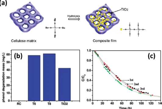
Zeng et al. [ 158 ] prepared TiO
2 /cellulose nanocomposite
fi lms using a sol–gel method through the hydrolysis of pre-cursor TiO 2 sol solutions in regenerated cellulose (RC) fi lms.
Figure 12 a shows the porous RC substrate providing cavities for the growth and immobilization of TiO 2 nanoparticles
through electrostatic and hydrogen bonding interactions.
Figure 11. a-i) SEM and ii) HRTEM images of Si/PEDOT nanowires. b) Relative band structures of Si/PEDOT and the proposed CT processes for photoelectrochemical water splitting. c-i) J – V curves of various photoanodes recorded in 1 M KOH in the dark and under light illumination (AM 1.5 G, 100 mW cm −2 ) and ii) J – t curves of different photoelectrodes recorded at a fi xed potential of +0.5 V (vs SCE). Reproduced with permission. [ 132 ] Copyright 2013, Royal Chemical Society.
Figure 12 b shows these TiO 2 /RC composite fi lms exhibited notable photocatalytic performance for the degradation of phenol under irradiation with weak UV light; their photocat-alytic activities were even comparable to that of anatase TiO 2
nanoparticles under the same experimental conditions, sug-gesting that the structure and properties of the TiO 2
nanopar-ticles were protected effectively. Moreover, Figure 12 c shows the TiO 2 /RC composite fi lms had good mechanical
proper-ties, allowing them to be used as recyclable catalysts for the photodegradation of organic pollutants.
3.5. Polymer-Immobilized ZnO-Based Composite Photocatalysts
An atomic layer deposition (ALD) approach was used to either decorate nylon nanofi bers with ZnO nanoparticles or to coat nylon nanofi bers with a thin layer of ZnO, depending on the ALD parameters. [ 165 ] When highly dense ZnO
nano-particles were decorated upon the nylon nanofi bers, they exhibited higher effi ciency for the photocatalytic decom-position of Rhodamine B (RhB), due to their large surface area. In addition to the ALD approach, the hydrothermal method is another practical method for immobilizing ZnO on polymeric supports. A combination of electrospinning and hydrothermal methods was employed for the preparation of hierarchical composites featuring oriented ZnO nanowires grown around electrospun nanofi bers. [ 171 ] The electrospun
nanofi bers were composed of cellulose acetate (CeAc), poly-vinyl acetate (PVAc), and polyethylene glycol (PEG). These hierarchical composites were highly effective photocatalysts, as evidenced by the almost complete removal of the test pollutant, methylene blue, after 30 min of UV irradiation.
Because the ZnO nanowires were grown on the CeAc/PVAc/ PEG polymeric supports, the need for separation of the pho-tocatalyst from the reaction solution was eliminated.
3.6. Other Types of Polymer-Immobilized Composite Photocatalysts
Figure 13 a shows that D201, a macroporous resin of poly-styrene-divinylbenzene matrix, was adopted as a support to fabricate D201-CdS composite photocatalysts using an ion exchange process. [ 179 ] Figure 13 b displays the as-obtained
D201-CdS beads were yellow, characteristic of the light absorption of CdS. Figure 13 c exhibits the composite pho-tocatalysts exhibited excellent photocatalytic activity for the degradation of RhB under irradiation with visible light. Furthermore, the photocorrosion of CdS was inhibited after immobilization within the D201 matrix. Figure 13 d shows the D201-CdS composite photocatalysts employed for repeated use without noticeable loss in effi ciency; in addition, they could be separated readily from the reaction solutions through simple fi ltration, suggesting their use as promising photocatalysts for practical applications in environmental remediation.
4. Conclusion
Conjugated polymer/nanocrystal QDs solar cells can exhibit PCEs of over 4% when using Cd- and Pb-based nanocrys-tals. Control over the polymer–nanocrystal QDs interface is a crucial factor affecting device performance. From a com-mercial point of view, postproduction treatment (ligand
Figure 12. a) Schematic representation of the growth and immobilization of TiO 2 nanoparticles in an RC matrix. b) Phenol photodegradation behavior of various samples under UV irradiation for 120 h. T6 and T8 represent TiO 2 /RC composite fi lms prepared from different volumes of the sol solution. c) Recycling tests of TiO 2 /RC fi lms for phenol degradation. Reproduced with permission. [ 158 ] Copyright 2010, American Chemical Society.
exchange; washing with acids) and methods for fi lm forma-tion (solvents choice) are considered more straightforward and tunable fabrication processes for improving effi ciency. It is also important to completely remove the capping ligands from the surfaces of the nanocrystal QDs to ensure more-intimate contact with the conjugated polymer. Such novel approaches include polymer grafting and the in situ synthesis of nanocrystal QDs in polymer solutions or polymer fi lms. These methods can provide important information regarding charge generation and recombination in highly effi cient next-generation devices. After optimization of device effi ciency, long-term stability is an issue that must be considered to minimize oxidation on the nanocrystals’ surfaces. For photo-catalysis using nanocrystal composites, structural and band gap engineering are both necessary to further improve light absorption from the solar spectrum. A fundamental under-standing of the CT processes occurring in composite photo-catalysts will be critical for maximizing the carrier utilization effi ciency in photocatalytic systems. Furthermore, developing generalized synthetic processes for solar fuel production in industrial settings will be the most important challenge for the practical applicability of reliable polymer/semiconductor nanocrystal composites.
[1] M. Helgesen , R. Sondergaard , F. C. Krebs , J. Mater. Chem. 2010 , 20 , 36 .
[2] J. Boucle , P. Ravirajan , J. Nelson , J. Mater. Chem. 2007 , 17 , 3141 .
[3] O. E. Semonin , J. M. Luther , M. C. Beard , Mater. Today 2012 , 15 , 508 .
[4] M. A. Green , Third Generation Photovoltaics , Springer, Berlin-Heidelberg 2003 .
[5] R. D. Schaller , M. A. Petruska , V. I. Klimov , Appl. Phys. Lett. 2005 , 87 , 253102 .
[6] R. J. Ellingson , M. C. Beard , J. C. Johnson , P. Yu , O. I Micic , A. J. Nozik , A. Shabaev , A. L. Efros , Nano Lett. 2005 , 5 , 865 . [7] J. J. H. Pijpers , R. Ulbricht , K. J. Tielrooij , A. Osherov , Y. Golan ,
C. Delerue , G. Allan , M. Bonn , Nat. Phys. 2009 , 5 , 811 . [8] D. Qi , M. Fischbein , M. Drndi , S. Šelmi , Appl. Phys. Lett. 2005 ,
86 , 093103 .
[9] A. J. Moule , L. Chang , C. Thambidurai , R. Vidu , P. Stroeve , J. Mater. Chem. 2012 , 22 , 2351 .
[10] T. Xu , Q. Qiao , Energy Environ. Sci. 2011 , 4 , 2700 . [11] F. Gao , S. Ren , J. Wang , Energy Environ. Sci. 2013 , 6 , 2020 . [12] J. Patel , F. Mighri , A. Ajji , T. K. Chaudhuri , Nano Energy 2014 , 5 ,
36 .
[13] J. Albero , J. N. Clifford , E. Palomares , Coord. Chem. Rev. 2014 , 263–264 , 53 .
[14] J. N. Freitas , A. S. Goncalves , A. F. Nogueira , Nanoscale 2014 , 6 , 6371 .
[15] Y. Park , R. C. Advincula , Chem. Mater. 2011 , 23 , 4273 .
[16] X. Chen , S. Shen , L. Guo , S. S. Mao , Chem. Rev. 2010 , 110 , 6503 .
[17] A. Furube , L. Du , K. Hara , R. Katoh , M. Tachiya , J. Am. Chem. Soc. 2007 , 129 , 14852
[18] S. K. Cushing , J. Li , F. Meng , T. R. Senty , S. Suri , M. Zhi , M. Li , A. D. Bristow , N. Wu , J. Am. Chem. Soc. 2012 , 134 , 15033 . [19] P. A. DeSario , J. J. Pietron , D. E. DeVantier , T. H. Brintlinger ,
R. M. Stroud , D. R. Rolison , Nanoscale 2013 , 5 , 8073 . [20] N. Zhang , S. Liu , Y.-J. Xu , Nanoscale 2012 , 4 , 2227 . [21] Y. Qu , X. Duan , Chem. Soc. Rev. 2013 , 42 , 2568 .
[22] Y. Wang , Q. Wang , X. Zhan , F. Wang , M. Safdar , J. He , Nanoscale 2013 , 5 , 8326 .
[23] S. R. Forrest , Nature 2004 , 428 , 911 .
[24] Y.-W. Su , S.-C. Lan , K.-H Wei , Mater. Today 2012 , 15 , 554 . [25] J.-M. Jiang , M. -C. Yuan , K. Dinakaran , A. Hariharan , K.-H. Wei ,
J. Mater. Chem. A 2013 , 1 , 4415 .
[26] L. Manna , E. C. Scher , A. P. Alivisatos , J. Am. Chem. Soc. 2000 , 122 , 12700 .
Figure 13. a) Schematic representation of the preparation of a D201-CdS composite photocatalyst. b) Photographs of pure D201 and D201-CdS. c) RhB degradation under various conditions: i) in the absence of D201-CdS, ii) in the presence of D201-CdS in the dark, and iii) in the presence of D201-CdS under irradiation with visible light. d) Recycling tests of CdS and D201-CdS for the degradation of RhB. Reproduced with permission. [ 179 ] Copyright 2011, IOP Publishing.
[27] X. Peng , L. Manna , W. Yang , J. Wickham , E. Scher , A. Kadavanich , A. P. Alivisatos , Nature 2000 , 404 , 59 .
[28] P. Reiss , J. Bleuse , A. Pron , Nano Lett. 2002 , 2 , 781 .
[29] E. Zillner , S. Fengler , P. Niyamakom , F. Rauscher , K. Köhler , T. Dittrich , J. Phys. Chem. C 2012 , 116 , 16747 .
[30] N. C. Greenham , X. Peng , A. P. Alivisatos , Phys. Rev. B 1996 , 54 , 17628 .
[31] Y. Wang , Nature 1992 , 356 , 585 .
[32] A. Biebersdorf , R. Dietmüller , A. S. Susha , A. L. Rogach , S. K. Poznyak , D. V. Talapin , H. Weller , T. A. Klar , J. Feldmann , Nano Lett. 2006 , 6 , 1559 .
[33] P. Brown , P. V. Kamat , J. Am. Chem. Soc. 2008 , 130 , 8890 . [34] J. H. Bang , P. V. Kamat , ACS Nano 2011 , 5 , 9421 .
[35] A. K. Bansal , F. Antolini , M. T. Sajjad , L. Stroea , R. Mazzaro , S. G. Ramkumar , K. J. Kass , S. Allard , U. Scherf , I. D. W. Samuel , Phys. Chem. Chem. Phys. 2014 , 16 , 9556 .
[36] W. U. Huynh , X. Peng , A. P. Alivisatos , Adv. Mater. 1999 , 11 , 923 .
[37] W. U. Huynh , J. J. Dittmer , A. P. Alivisatos , Science 2002 , 295 , 2425 .
[38] I. Gur , N. A. Fromer , C.-P. Chen , A. G. Kanaras , A. P. Alivisatos , Nano Lett. 2006 , 7 , 409 .
[39] B. Sun , N. C. Greenham , Phys. Chem. Chem. Phys. 2006 , 8 , 3557 .
[40] J. D. Olson , G. P. Gray , S. A. Carter , Sol. Energy Mater. Sol. Cells 2009 , 93 , 519 .
[41] J. Yang , A. Tang , R. Zhou , J. Xue , Sol. Energy Mater. Sol. Cells 2011 , 95 , 476 .
[42] Y. Zhou , F. S. Riehle , Y. Yuan , H. F. Schleiermacher , M. Niggemann , G. A. Urban , M. Krüger , Appl. Phys. Lett. 2010 , 96 , 013304.
[43] J. Albero , P. Riente , J. N. Clifford , M. A. Pericàs , E. Palomares , J. Phys. Chem. C 2013 , 117 , 13374 .
[44] L. Qian , J. Yang , R. Zhou , A. Tang , Y. Zheng , Tseng, T.-K. D. Bera , J. Xue , P. H. Holloway , J Mater Chem 2011 , 21 , 3814 .
[45] S. Ren , L.-Y. Chang , S.-K. Lim , J. Zhao , M. Smith , N. Zhao , V. Bulovic´ , M. Bawendi , S. Gradeˇcak , Nano Lett. 2011 , 11 , 3998 .
[46] R. Zhou , R. Stalder , D. Xie , W. Cao , Y. Zheng , Y. Yang , M. Plaisant , P. H. Holloway , K. S. Schanze , J. R. Reynolds , J. Xue , ACS Nano 2013 , 7 , 4846 .
[47] M. D. Heinemann , K. Von Maydell , F. Zutz , J. Kolny-Olesiak , H. Borchert , I. Riedel , J. Parisi , Adv. Funct. Mater. 2009 , 19 , 3788 .
[48] D. S. Ginger , N. C. Greenham , Phys. Rev. B 1999 , 59 , 10622 . [49] B. Sun , E. Marx , N. C. Greenham , Nano Lett. 2003 , 3 , 961 . [50] B. Sun , H. J. Snaith , A. S. Dhoot , S. Westenhoff , N. C. Greenham ,
J. Appl. Phys. 2005 , 97 , 014914.
[51] H. J. Snaith , G. L. Whiting , B. Sun , N. C. Greenham , W. T. S. Huck , R. H. Friend , Nano Lett. 2005 , 5 , 1653 .
[52] M. L. Böhm , R. J. P. Kist , F. S. F. Morgenstern , B. Ehrler , S. Zarra , A. Kumar , Y. Vaynzof , N. C. Greenham , Adv. Energy Mater. 2014 , DOI 10.1002/aenm.201400139 .
[53] F. S. F. Morgenstern , A. Rao , M. L. Böhm , R. J. P. Kist , Y. Vaynzof , N. C. Greenham , ACS Nano 2014 , 8 , 1647 .
[54] P. Wang , A. Abrusci , H. M. P. Wong , M. Svensson , M. R. Andersson , N. C. Greenham , Nano Lett. 2006 , 6 , 1789 . [55] S. Dayal , N. Kopidakis , D. C. Olson , D. S. Ginley , G. Rumbles ,
Nano Lett. 2009 , 10 , 239 – 242 .
[56] R. Zhou , Y. Zheng , L. Qian , Y. Yang , P. H. Holloway , J. Xue , Nanoscale 2012 , 4 , 3507 .
[57] J. Albero , Y. Zhou , M. Eck , F. Rauscher , P. Niyamakom , I. Dumsch , S. Allard , U. Scherf , M. Kruger , E. Palomares , Chem. Sci. 2011 , 2 , 2396 .
[58] Y. Zou , A. Najari , P. Berrouard , S. Beaupré , B. Réda Aïch , Y. Tao , M. Leclerc , J. Am. Chem. Soc. 2010 , 132 , 5330 .
[59] C.-Y. Kuo , M.-S. Su , G.-Y. Chen , C.-S. Ku , H.-Y. Lee , K.-H. Wei , Energy Environ. Sci. 2011 , 4 , 2316 .
[60] S. A. McDonald , G. Konstantatos , S. Zhang , P. W. Cyr , E. J. D. Klem , L. Levina , E. H. Sargent , Nat. Mater. 2005 , 4 , 138 . [61] A. A. R. Watt , D. Blake , J. H. Warner , E. A. Thomsen ,
E. L. Tavenner , H. Rubinsztein-Dunlop , P. Meredith ,. J. Phys. D: Appl. Phys. 2005 , 38 , 2006 .
[62] K. M. Noone , E. Strein , N. C. Anderson , P.-T. Wu , S. A. Jenekhe , D. S. Ginger , Nano Lett. 2010 , 10 , 2635 .
[63] J. Seo , M. J. Cho , D. Lee , A. N. Cartwright , P. N. Prasad , Adv. Mater. 2011 , 23 , 3984 .
[64] A. E. Colbert , E. M. Janke , S. T. Hsieh , S. Subramaniyan , C. W. Schlenker , S. A. Jenekhe , D. S. Ginger , J. Phys. Chem. Lett. 2012 , 4 , 280 .
[65] E. Strein , A. Colbert , S. Subramaniyan , H. Nagaoka , C. W. Schlenker , E. Janke , S. A. Jenekhe , D. S. Ginger , Energy Environ, Sci 2013 , 6 , 769 .
[66] C. Piliego , M. Manca , R. Kroon , M. Yarema , K. Szendrei , M. R. Andersson , W. Heiss , M. A. Loi , J. Mater. Chem. 2012 , 22 , 24411 .
[67] J. M. Luther , M. Law , M. C. Beard , Q. Song , M. O. Reese , R. J. Ellingson , A. J. Nozik , Nano Lett. 2008 , 8 , 3488 .
[68] W. Ma , J. M. Luther , H. Zheng , Y. Wu , A. P. Alivisatos , Nano Lett. 2009 , 9 , 1699 .
[69] M. Nam , S. Kim , S. Kim , S.-W. Kim , K. Lee , Nanoscale 2013 , 5 , 8202 .
[70] M. Nam , J. Park , S.-W. Kim , K. Lee , J. Mater. Chem. A 2014 , 2 , 3978 .
[71] H. Nagaoka , A. E. Colbert , E. Strein , E. M. Janke , M. Salvador , C. W. Schlenker , D. S. Ginger , J. Phys. Chem. C 2014 , 118 , 5710 . [72] A. Maria , P. W. Cyr , E. J. D. Klem , L. Levina , E. H. Sargent , Appl.
Phys. Lett. 2005 , 87 , 213112.
[73] Y. Zhang , Z. Li , J. Ouyang , S.-W. Tsang , J. Lu , K. Yu , J. Ding , Y. Tao , Org. Electron. 2012 , 13 , 2773 – 2780 .
[74] R. D. Schaller , V. I. Klimov , Phys. Rev. Lett. 2004 , 92 , 186601 . [75] D. Cui , J. Xu , T. Zhu , G. Paradee , S. Ashok , M. Gerhold , Appl.
Phys. Lett. 2006 , 88 , 183111 .
[76] X. Jiang , R. D. Schaller , S. B. Lee , J. M. Pietryga , V. I. Klimov , A. A. Zakhidov , J. Mater. Res. 2007 , 22 , 2204 .
[77] K. M. Noone , N. C. Anderson , N. E. Horwitz , A. M. Munro , A. P. Kulkarni , D. S. Ginger , ACS Nano 2009 , 3 , 1345 .
[78] G. I. Koleilat , L. Levina , H. Shukla , S. H. Myrskog , S. Hinds , A. G. Pattantyus-Abraham , E. H. Sargent , ACS Nano 2008 , 2 , 833 .
[79] C.-Y. Kuo , M.-S. Su , Y.-C. Hsu , H.-N. Lin , K.-H. Wei , Adv. Funct. Mater. 2010 , 20 , 3555 .
[80] C.-Y. Kuo , M.-S. Su , C.-S. Ku , S.-M. Wang , H.-Y. Lee , K.-H. Wei , J. Mater. Chem. 2011 , 21 , 11605 .
[81] N. Zhao , T. P. Osedach , L.-Y. Chang , S. M. Geyer , D. Wanger , M. T. Binda , A. C. Arango , M. G. Bawendi , V. Bulovic , ACS Nano 2010 , 4 , 3743 .
[82] R. Debnath , J. Tang , D. A. Barkhouse , X. Wang , A. G. Pattantyus-Abraham , L. Brzozowski , L. Levina , E. H. Sargent , J Am. Chem. Soc. 2010 , 132 , 5952 .
[83] W. Yoon , J. E. Boercker , M. P. Lumb , D. Placencia , E. E. Foos , J. G. Tischler , Sci. Rep. 2013 , 3 , 2225.
[84] A. G. Pattantyus-Abraham , I. J. Kramer , A. R. Barkhouse , X. Wang , G. Konstantatos , R. Debnath , L. Levina , I. Raabe , M. K. Nazeeruddin , M. Grätzel , E. H. Sargent , ACS Nano 2010 , 4 , 3374 .
[85] J. Tang , K. W. Kemp , S. Hoogland , K. S. Jeong , H. Liu , L. Levina , M. Furukawa , X. Wang , R. Debnath , D. Cha , K. W. Chou , A. Fischer , A. Amassian , J. B. Asbury , E. H. Sargent , Nat. Mater. 2011 , 10 , 765 .
[86] A. H. Ip , S. M. Thon , S. Hoogland , O. Voznyy , D. Zhitomirsky , R. Debnath , L. Levina , L. R. Rollny , G. H. Carey , A. Fischer , K. W. Kemp , I. J. Kramer , Z. Ning , A. J. Labelle , K. W. Chou , A. Amassian , E. H. Sargent , Nat. Nanotechnol. 2012 , 7 , 577 . [87] G.-H. Kim , B. Walker , H.-B. Kim , J. Y. Kim , E. H. Sargent , J. Park ,