圓弧齒線圓柱型齒輪之特性研究
68
0
0
全文
(2) 圓弧齒線圓柱型齒輪之特性研究 A Characteristic Study on Cylindrical Gears with Circular Arc Tooth Traces 研 究 生:曾瑞堂. Student:Jui-Tang Tseng. 指導教授:蔡忠杓. Advisor:Chung-Biau Tsay. 國 立 交 通 大 學 機械工程學系 博 士 論 文 A Dissertation Submitted to Department of Mechanical Engineering College of Engineering National Chiao Tung University in Partial Fulfillment of the Requirements for the Degree of Doctor of Philosophy in Mechanical Engineering. June 2005. Hsinchu, Taiwan, Republic of China. 中華民國九十四年六月.
(3) 圓弧齒線圓柱型齒輪之特性研究 研究生:曾瑞堂. 指導教授:蔡忠杓博士 國立交通大學機械工程學系. 摘要 曲線齒輪(具有圓弧齒線之圓柱型齒輪)通常是由專用機配合盤 狀銑刀來加工製作,其切削效率較低,本研究提出另一種製造方式, 即利用六軸 CNC 滾齒機配合一般滾刀來切製曲線齒輪。由於滾齒切削 過程為連續分度,其切削效率將大幅提高。使用六軸 CNC 滾齒機來創 成曲線齒輪是一新的製造方式,在創成的過程中,滾刀座之角速度必 須是可以控制的,而使得滾刀座之旋轉角速度可與滾刀軸向進給速度 互相配合來滾製曲線齒輪。然而,本研究所提以滾刀來創成曲線齒輪 之新方法,必須克服齒面過切及齒面二次切削等問題。 本文依據六軸 CNC 滾齒機之創成機構及滾刀之幾何外形來建立曲 線齒輪之齒面數學模式,並探討製造過程中的齒面過切現象及齒面二 次切削等問題。其中,曲線齒輪之齒面過切問題係以 Litvin 教授所提 之方法來分析,而本文也建立分析齒面二次切削之程式,討論齒面發 生二次切削時滾刀外徑與圓弧齒線半徑之間的關係。由於本研究所探 討之曲線齒輪其齒面為雙參數之包絡曲面,對於齒面之曲率分析,目 前文獻中並無相關之計算式,故本文亦推導曲線齒輪之齒面曲率分析. -i-.
(4) 計算式及其電腦模擬程式。齒輪接觸分析技術將應用於討探曲線齒輪 對之齒面嚙合特性。對於曲線齒輪對在具有水平軸、垂直軸及中心距 組裝偏差時,其齒面接觸位置、運動誤差及接觸齒印之變化情形均加 以研究。最後,依據所推導出之曲線齒輪數學模式,發展建構具有三 對齒之有限單元應力分析模型程式,並利用有限單元分析軟體 ABAQUS,進行三對齒之齒面接觸應力及齒根彎曲應力分析。 分析結果顯示曲線齒輪之齒面寬兩端容易產生較嚴重的齒面過 切。在相同的齒線圓弧半徑下,使用較大的壓力角或較小的滾刀外徑 可以避免齒面發生二次切削。本研究之曲線齒輪組為點接觸,故齒輪 組對於組裝偏差並不敏感。應力分析之結果則顯示當接觸點接近節點 時,齒面將有最大的接觸應力及齒根彎曲應力,而使用較大的齒線圓 弧半徑將可降低齒面接觸應力及齒根彎曲應力。. -ii-.
(5) A Characteristic Study on Cylindrical Gears with Circular Arc Tooth Traces Student: Jui-Tang Tseng. Advisor: Dr. Chung-Biau Tsay. Department of Mechanical Engineering National Chiao Tung University. ABSTRACT In general, the tooth surfaces of the curvilinear-tooth gear (cylindrical gears with circular arc tooth trace) are generated by the special machine with gear milling cutters. However, the efficiency of this type of gear generation is lower than that of hobbing. The curvilinear-tooth gear cut by a hob cutter is proposed in this study. Since the generation of gear teeth is a continuous-indexing process, the cutting efficiency of the curvilinear-tooth gear generated by hobbing will be increased substantially. Therefore, the proposed hobbing method is applicable to mass production for the curvilinear-tooth gear. The proposed method by applying a 6-axis CNC hobbing machine to generate the curvilinear-tooth gear is a novel method. The angular velocity of the hob’s swivel must be controllable and correlative with the linear velocity of the axial feeding motion in the process of gear generation. However, the problems of tooth undercutting and secondary cutting of tooth surfaces by a hob cutter in the proposed novel generating process need to be solved. In this study, the geometry of a hob cutter was constructed at first, and then the mathematical model of the curvilinear-tooth gear cut by a hob cutter based on proposed the cutting mechanism for a 6-axis CNC hobbing machine was developed. Sequentially, the theoretical analysis on the tooth undercutting and secondary cutting of the gear teeth in the generating process were also investigated. The method -iii-.
(6) proposed by Litvin was used to analyze the tooth undercutting of the curvilinear-tooth gear. The computer algorithm for investigation on the relationship between the outside diameter of the hob cutter and nominal radius of circular arc tooth trace without secondary cutting was developed. Because the tooth surfaces of the curvilinear-tooth gear are the envelope as two-parameter family of surfaces, literature search for the curvature analysis of the proposed curvilinear-tooth gear is not available. An algorithm for computerized determination of principal curvatures and directions of the curvilinear-tooth gear, as the envelope to two-parameter family of surfaces, was also proposed. Tooth contact analysis was applied to find the contact characteristic of the curvilinear-tooth gear pair such as bearing contacts, kinematic errors, contact ellipses of the curvilinear-tooth gear having center distance assembly errors, horizontal axialmisalignments, and vertical axial misalignments. Finally, The input file for the commercial software, ABAQUS/Standard, was generated automatically by the integrated computer programs. A pair of three-meshing-teeth finite element model was formed to investigate the contact stresses and bending stresses of the curvilinear-tooth gears. The analysis results show that the serious tooth undercutting is at the both-end sections of face width of the curvilinear-tooth gear, and increasing the normal pressure angle or decreasing the outside diameter of the hob cutter can avoid secondary tooth cutting under the same nominal radius of circular arc tooth traces. The KE of the gear pair is not sensitive to axial misalignments because the contact type of the proposed curvilinear-tooth gear pair is in point contacts. The maximum contact stress and bending stress occur when the contact point is near the pitch point, and increasing the nominal radius of circular arc tooth trace reduces the contact stresses and bending stresses.. -iv-.
(7) Acknowledgement (誌謝) 本論文承蒙指導教授 蔡忠杓博士殷切指導,在論文上諸多啟 發,並逐字斧正,使得本論文終能順利完成。感謝您在研究工作上不 斷地指引與鼓勵,在論文寫作方面不厭其煩地指導與指正,而您在待 人處事面所展現的誠懇與執著,更讓學生深感佩服,學生除了由衷的 感激外,並時時刻刻記得您的諄諄教誨。 感謝我的口試委員:國科會國家實驗研究院翁董事長政義、清華 大學陳副校長文華、中央大學王院長國雄、清華大學宋教授震國、工 研院機械所陳副所長正、交通大學曾教授錦煥及洪教授景華,謝謝您 能於百忙之中撥冗前來主持學生的博士論文口試,並提供學生許多論 文修正上的寶貴建議,學生在此表示衷心的感謝。 感謝怡呈及家彰學長在研究上的幫助,與您互相討論讓我獲益良 多。感謝冠宇、明達、志榮、立碁、偉旭、俊諭、政豪及嘉宏等學弟 在課業或生活上的幫助,使我在學習的過程中有互相切磋的機會。有 學長及學弟的幫助使得本論文更臻完善。另外,也要感謝陳經理義 仁,謝謝您提供齒輪加工方面的經驗。 在求學過程中,父母親與姊弟總是默默地支持與關懷,而靜芳多 年來的陪伴與包容,使得我的研究工作,能心無旁騖地向目標前進, 在此謹將此論文獻給至愛的父母、姊弟與靜芳,以表示我對你們的感 激。. -v-.
(8) Table of Contents ABSTRACT………………………………………………………………………. i. ACKNOWLEDGEMENT………………………………………………………... v. TABLE OF CONTENTS…………………………………………………………. vi. LIST OF TABLES………………………………………………………………... viii. LIST OF FIGURES………………………………………………………………. x. NOMENCLATURE……………………………………………………………... xiii. CHAPTER 1 Introduction……………………………………………………... 1. 1.1 Features of Curvilinear-Tooth Gears……………………………………. 1. 1.2 Literature Reviews………………………………………………………. 3. 1.3 Motivation………………………………………………………………. 6. 1.4 Overview………………………………………………………………... 7. CHAPTER 2 Mathematical Model of Cylindrical Gears with Circular Arc Tooth Traces……………………………………………………. 10. 2.1 Introduction……………………………………………………………. 10. 2.2 Generation Method for Curvilinear-Tooth Gears…………………….... 11. 2.3 Equation of the Hob Cutter…………………………………………….. 14. 2.4 Relative Velocity and Equation of Meshing………………………….. .. 19. 2.5 Mathematical Model of the Curvilinear-Tooth Gear…………………... 23. 2.6 Computer Graphs of the Curvilinear-Tooth Gear. …………………….. 23. 2.7 Surface Deviations of the Curvilinear-Tooth Gear…………………….. 25. 2.8 Remarks………………………………………………………………... 26. CHAPTER 3 Tooth Undercutting and Secondary cutting………………….. 30. 3.1 Introduction…………………………………………………………….. 30. 3.2 Tooth undercutting of the Curvilinear-Tooth Gear……………………... 31. 3.3 Numerical Examples for Tooth Undercutting of Curvilinear-Tooth Gear. 38. 3.4 Secondary tooth Cuttings……………………………………………….. 41. 3.5 Remarks……………………………………………………..………….. 48. CHAPTER 4 Curvature Analysis………………………………………..……. 51. 4.1 Introduction…………………………………………………………….. 51. 4.2 Relations Between Relative Velocities…………………………………. 52. -vi-.
(9) 4.3 Relations Between Mating Surface Curvatures…………………………. 54. 4.4 Principal Curvatures and Directions of the Hob Cutter……………….. 60. 4.5 Numerical Examples ………………………………………………….. 62. 4.6 Remarks……………………………………………………………….. 67. CHAPTER 5 Tooth Contact Analysis……………………………………….. 68. 5.1 Introduction…………………………………………………………... 68. 5.2 Simulation of Gear Meshing………………………………………….. 69. 5.3 Kinematic Errors……………………………………………………... 72. 5.4 Contact Ellipses………………………………………………………. 74. 5.4.1 Curvature Analysis Method……………………………………. 74. 5.4.2 Surface Topology Method……………………………………... 76. 5.5 Numerical Examples for Gear Meshing Simulations…………………. 81. 5.6 Remarks……………………………………………………………….. 96. CHAPTER 6 Finite Element Stress Analysis……………………………….. 99. 6.1 Introduction……………………………………… …………………... 99. 6.2 Finite Element Contact Model……………………………………….. 100. 6.2.1 Finite Element meshes………………………………………... 100. 6.2.2 Surface Definition and Interaction Properties………..……….. 101. 6.2.3 Boundary Conditions and Loads……………………………... 103. 6.3 Simulation Results and Discussions…………………………………. 105. 6.4 Remarks………………………………………………………………. 107. CHAPTER 7 Conclusions and Future Work………………………………. 116. 7.1 Conclusions………………………………………………………….. 116. 7.2 Future Work…………………………………………………………. 118. REFERENCES………………………………………………………………. 120. VITA………………………………………………………………………….. 125. -vii-.
(10) List of Tables Table 2.1. Some major design parameters for cylindrical gears with circular arc tooth traces………………………………………………………….. Table 3.1 Location of singular points under different design parameters………. 24 39. Table 4.1 Some major design parameters for cylindrical gears with circular arc tooth traces……………………………………………………………. 64. Table 4.2 Principal curvatures and directions at cross section Z f =0 mm on tooth surface Σ 2 L when nominal radius Rc =110 mm……………... 65. Table 4.3 Principal curvatures and directions at cross section Z f =0 mm on tooth surface Σ 2 R when nominal radius Rc =110 mm……………... 66. Table 4.4 Principal curvatures and directions at cross section Z f =0 mm on tooth surface Σ 2 L when nominal radius Rc =5000 mm…………….. 66. Table 4.5 Principal curvatures and directions at cross section Z f =0 mm on tooth surface Σ 2 R when nominal radius Rc =5000 mm…………….. 66. Table 5.1 Some major design parameters for cylindrical gears with circular arc tooth traces……………………………………………………………. 82. Table 5.2 kinematic errors and bearing contacts under the ideal meshing condition ( Rcp = Rcg = 110 mm) ……………………………………... 82. Table 5.3 kinematic errors and bearing contacts due to horizontal axial misalignment Δγ h = 3′ ( Rcp = Rcg = 110 mm)…………………….. 85. Table 5.4 kinematic errors and bearing contacts due to horizontal axial misalignment Δγ h = 3′ ( Rcp = 110 mm and Rcg = 113 mm)………... 89. Table 5.5 kinematic errors and bearing contacts due to vertical axial misalignment Δγ v = 3′ ( Rcp = 110 mm and Rcg = 113 mm)………... 89. Table 5.6 kinematic errors and bearing contacts due to center distance variation ΔC = 0.2 mm ( Rcp = 110 mm and Rcg = 113 mm)……………………. 90. Table 5.7 kinematic errors and bearing contacts due to assembly error -viii-.
(11) ΔZ = 0.1 mm ( Rcp = 110 mm, Rcg = 113 mm)………………………... 92. Table 5.8 kinematic errors and bearing contacts under Δγ h = 3′ , Δγ v = 3′ , and ΔC = 0.2 mm ( Rcp = 110 mm, Rcg = 113 mm)…………………... 93. Table 5.9 kinematic errors and bearing contacts under Δγ h = 3′ , Δγ v = 3′ , ΔC = 0.2 mm, and ΔZ = 0.1 mm ( Rcp = 110 mm, Rcg = 113 mm)…... 95. Table 6.1 Major design parameters for the curvilinear-tooth gear……………... 103. Table 6.2 Material properties for the gears…………………………..…………. 105. Table 6.3 Finite element models for the investigated gear pair………………… 106. -ix-.
(12) List of Figures Fig. 1.1. Various types of tooth traces for parallel axis gears………………... 2. Fig. 2.1. A schematic drawing of a 6-axis CNC hobbing machine…………... 11. Fig. 2.2. Generating method of a curvilinear-tooth gear cut by hob cutters…………………………………………………………..…. Fig. 2.3. Geometry of the straight-edged cutting blade and worm-type hob cutter……………………………………………………………... Fig. 2.4. 15. Relations between the hob cutter and cutting blade coordinate system……………………………………………………………. Fig. 2.5. 12. 17. Coordinate systems of the hob cutter and CNC hobbing machine………………………………………………………..…. 20. Fig. 2.6. Computer graph of the curvilinear-tooth gear………………….... 24. Fig. 2.7. Different tooth profiles of the curvilinear-tooth gear generated by Rc =100 mm, 120 mm and 200 mm…….………………………... 27. Fig. 2.8. Transverse chordal thickness on different cross section…………. 28. Fig. 2.9. Thickness of tooth at addendum circle on different cross section. 28. Fig. 3.1. Simulation of a generation mechanism with two-parameter motion…………………………………………………………….. Fig. 3.2. Location of singular points under different numbers of teeth……………………………………………………………….. Fig. 3.3. Location. of. singular. points. under. different. 42. Secondary cutting occurs on the tooth surface Σ 2b when the tooth surface Σ 2 a is generated……………….………………….. Fig. 3.5. 42. nominal. radii………………………………………………………………. Fig. 3.4. 34. 44. Relations between the vector r f(1) − r f( 2) and unit normal vector n (f2) ………………………………………………………………... 46. Flowchart for determination of secondary cutting……………….. 47. Fig. 3.7 (a) An example for secondary tooth cutting…………………………. 49. Fig. 3.6. Fig. 3.7 (b) The analysis result for secondary tooth cutting region on tooth -x-.
(13) surfaces…………………………………………………………... Fig. 3.8. 49. Relationship between the outside diameter of hob cutter and nominal radius of circular arc tooth trace for secondary cutting…………………………………………………………….. Fig. 4.1. Simulation of a generation mechanism with two-parameter motion…………………………………………………………….. Fig. 4.2. 53. Principal direction of mating surfaces represented in tangent plane………………………………………………………………. Fig. 4.3. 50. 55. Flowchart for the determination of the principal curvatures and directions for the envelope surface of family of tool surface…………………………………………………………….. Fig. 4.4. 63. The concave surface and convex surface of the curvilinear-tooth gear…………………………………………………………….….. 64. Fig. 5.1. Simulation of gear meshing with assembly errors………………... 70. Fig. 5.2. Orientation and dimension of contact ellipse…………………….. 75. Fig. 5.3 (a) Common tangent plane and polar coordinates……………………. 78. Fig. 5.3 (b) Measurement on surface separation……………………………..... 78. Fig. 5.4. Relationship among coordinate system S f , S p , S q , and ST …….. 80. Fig. 5.5. Kinematic errors of the curvilinear-tooth gear pair under ideal meshing condition……………………..………………………….. Fig. 5.6. 83. Contact ellipses and bearing contacts on the pinion surface under ideal assembly condition……………………………….…………. 84. Fig. 5.7. Relationship between the ratio a / b and nominal radius Rc ….. 84. Fig. 5.8. Contact ellipses and bearing contacts on the pinion surface under. Fig. 5.9. Fig. 5.10. idea assembly condition…………………………………………... 87. Contact ellipses and bearing contacts on the pinion surface under horizontal axial misalignment Δγ h = 3′ …………………………. 88. Contact ellipses and bearing contacts on the pinion surface under vertical axial misalignment Δγ v = 3′ ……………………………. 91. -xi-.
(14) Fig. 5.11. Fig. 5.12. Fig. 5.13. Contact ellipses and bearing contacts on the pinion surface under an assembly error ΔZ = 0.1 mm…………………………………. 94. Contact ellipses and bearing contacts on the pinion surface with assembly errors Δγ h = 3′ , Δγ v = 3′ , and ΔC = 0.2 mm…….…. 97. Contact ellipses and bearing contacts on the pinion surface with assembly errors Δγ h = 3′ , Δγ v = 3′ , ΔC = 0.2 mm, and. ΔZ = 0.1 mm…………………………………………………….... 98. Fig. 6.1. A pair of three-teeth finite element meshing model…..…………... 102. Fig. 6.2. FEA model of a pair of three-meshing-teeth with boundary conditions…………………………………………………………. Fig. 6.3. Bearing contacts and stress distributions at beginning point of contact on the gear concave surfaces……………………………... Fig. 6.4. 110. Variations of contact stresses during one tooth of gear pair meshing………………………………………………………….... Fig. 6.7. 109. Bearing contacts and stress distributions at the end point of contact on the gear concave surfaces………………………….….. Fig. 6.6. 108. Bearing contacts and stress distributions at the mean point of contact on the gear concave surfaces………………………….….. Fig. 6.5. 104. 111. Variation of bending stresses during one tooth of gear pair meshing…………………………………………………………... 112. Fig. 6.8. Effects of nominal radius Rc on the maximum von Mises stress. 113. Fig. 6.9. Stress distributions on gear tooth surfaces as nominal radius Rc equals 50000 mm…………………………………………………. -xii-. 114.
(15) Nomenclature a. half length of the major axes of the contact ellipse, as shown in Fig. 5.2. b. half length of the minor axes of the contact ellipse, as shown in Fig. 5.2. bn. normal groove width of the hob cutter, as shown in Fig. 2.3. e f , eh. unit vectors of the principal directions of surface Σ1 , as shown in Fig. 4.2. es , eq. unit vectors of the principal directions of surface Σ 2 , as shown in Fig. 4.2. e Ι(i ) , e ΙΙ(i ). principal directions of surface Σ i ( i = p, g ). l. surface parameter of the hob cutter. l1. parameter of the straight-lined cutting blade surface. lh. shift along the hob’s spindle axis. lL. parameter of the surface coordinate of the convex tooth surface. lg , l p. tooth surface parameters of the gear and pinion. lx. center distance between the hob cutter and work piece. lz. axial feed displacement. lE. tip of addendum on the tooth surface. lR. parameter of the surface coordinate of the concave tooth surface. lS. starting point of the working curve on the tooth surface. mc. contact ratio. n. unit normal vector. nxf , n yf , nzf components of the unit normal vector represented in coordinate system Sf n (f p ) , n (fg ) unit normal vectors of pinion and gear represented in coordinate system. Sf p x , p y , p z coordinate components of the instantaneous contact point (r , θ ). auxiliary polar coordinate system, as shown in Fig. 5.3(a). r1. pitch radius of the hob cutter (in mm), as shown in Fig. 2.3. r2. radius of operating pitch cylinder of the work piece (in mm). rf. root radius of the hob cutter (in mm), as shown in Fig. 2.3. ro. outside radius of the hob cutter (in mm), as shown in Fig. 2.3. -xiii-.
(16) rll , rlφ , rφφ partial derivative of surface equation r1(1) r1(1). surface equation of the hob cutter represented in coordinate system S1. r2( 2 ). locus of the hob cutter surface represented in coordinate system S 2. ta. thickness of tooth at the addendum circle (in mm). tc. transverse chordal thickness (in mm). x f , y f , z f components of the position vector represented in coordinate system S f C. ideal center distance of the gear pair (in mm), as shown in Fig. 5.1. C′. operational center distance of the gear pair (in mm), as shown in Fig. 5.1. D. relative-position vector, as shown in Fig. 2.5. Do. outside diameter of the hob cutter (in mm). FEM. finite element method. H. mean curvature. K. Gaussian curvature. KE. kinematic error of the mating gear pair. L ij. vector transformation matrix transforming from S j to Si. Mn. normal module (in mm). M ij. homogeneous coordinate transformation matrix transforming from coordinate system S j to Si. N (ij ). normal vector of surface represented in coordinate system S j. P1. lead-per-radian revolution of the hob cutter’s surface. P (1) , P ( 2). position vectors, as shown in Fig. 2.5. Rc. nominal radius of circular arc tooth trace (in mm). Rcg , Rcp nominal radii of circular arc tooth trace of the gear and pinion (in mm) Rcmin. minimum nominal radius of circular arc tooth trace without secondary cutting (in mm). R. (i ). position vector of the surfaces Σ i ( i = 1, 2 ), as shown in Fig. 3.1. TCA. tooth contact analysis of the gear pair. T1. number of threads of the hob cutter. T2. number of teeth of the generated gear. Tg , Tp. numbers of teeth of gear and pinion -xiv-.
(17) Si ( X i , Yi , Z i ) coordinate system i ( i = 1, 2, b, v, h, p, g , f , q, T ) Vz. linear velocity of axial feed motion of the hob cutter. (i ) Vabs. absolute velocity of the contact point on tooth surface Σ i. V f(12 ). relative velocity of body 1 and body 2, represented in coordinate system Sf. V f( i ). velocity of point M attached to the body i represented in coordinate system S f. Vr( 2 ). relative velocity of the contact point over the generated surface. V (12, j ). relative velocity of body 1 and body 2, at the instantaneous common contact point, when parameter j = θ (or ψ ) is varied and parameter. ψ (or θ ) is fixed V (i , j ). velocity of point M attached to the body i when parameter j = θ (or ψ ) is varied and parameter ψ (or θ ) is fixed. αn. half-apex blade angle, as shown in Fig. 2.3. β. lead angle of the hob cutter, as shown in Fig. 2.3. γ. angle measured from the minor axis of the contact ellipse to the first principal direction of the pinion, as shown in Fig. 5.2. δ. elastic deformation of the material. θ. rotational angle about hob’s swivel axis, as shown in Fig. 2.2. k f , kh. principal curvatures of tool surface Σ1. ks , kq. principal curvatures of tooth surface Σ 2. k Ι(i ) , k ΙΙ(i ) principal curvatures of surfaces Σ i ( i = p, g ). λ. angle measured from axis Z q to axis Z T , as shown in Fig. 5.4. ρ(1) , ρ ( 2 ) position vectors, as shown in Fig. 3.1. σ. angle formed by the vectors e f and e s , as shown in Fig. 4.2. σ. angle measured from axis Z p to axis Z q , as shown in Fig. 5.4. σ. angle formed by the first principal directions, e Ι(1) and e (Ι 2 ) , of the pinion and gear tooth surfaces, as shown in Fig. 5.2. φ. surface parameters of the hob cutter. φ1. rotational angle in relevant screw motion, as shown in Fig. 2.4(b) -xv-.
(18) φ2. rotational angles of the work piece, as shown in Fig. 2.2. φg , φ p. tooth surface parameters of the gear and pinion. φ1′. rotational angles of the pinion, as shown in Fig. 5.1. φ2′. rotational angles of the gear, as shown in Fig. 5.1. φ1′B. rotational angle of the pinion corresponding to the point of contact in the beginning of meshing. φ1′E. rotational angle of the pinion corresponding to the point of contact in the end of meshing for the same pair of profiles. φ2′ (φ1′). actual rotational angle of the gear meshing under various assembly conditions. ψ. rotational angle of the hob cutter’s spindle, as shown in Fig. 2.2. ω2. angular velocity of work piece. ωA. angular velocity with respect to hob’s swivel axis. ωB. angular velocity with respect to hob’s spindle axis. ω (1). angular velocity of hob cutter (vector). ω ( 2). angular velocity of work piece (vector). ω (i , j ). angular velocity of body i when parameter j = θ (or ψ ) is varied and parameter ψ (or θ ) is fixed (vector). ΔC. center distance variations (in mm). ΔZ. assembly error along the rotational axis Z g , measured from Og′ to Og , as shown in Fig. 5.1. Δγ h. horizontal axial misaligned angle, as shown in Fig. 5.1. Δγ v. vertical axial misaligned angle, as shown in Fig. 5.1. Δφ2. additional angle of work piece rotation due to the hob’s feed motion. Δφ 2′ (φ1′). kinematic error of the gear pair (in arc-sec.). Σ1 , Σ 2. surfaces of cutter and tooth. Σ 2i. concave surfaces of the curvilinear-tooth gear ( i = a, b ), as shown in Fig.3.4. Σ 2 L , Σ 2 R concave and convex tooth surfaces of the curvilinear-tooth gear, as shown. in Fig. 4.4 -xvi-.
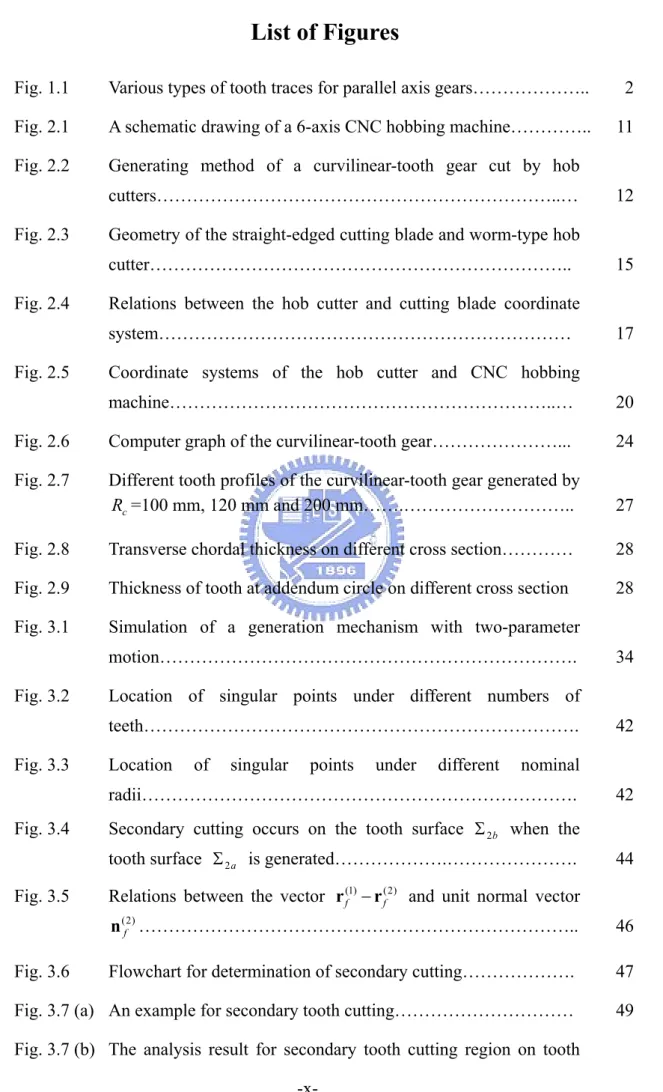
(19) CHAPTER 1 Introduction. 1.1 Features of the Curvilinear-Tooth Gear Cylindrical gears are frequently used in industry for transmitting powers with high efficiency. There are several types of cylindrical gears, such as spur gear, helical gear, and herringbone gear, that can be used to transmit powers for parallel axis gearing. The tooth traces on the spur gear, helical gear, and herringbone gear are shown in Fig. 1.1(a), 1.1(b), and 1.1(c), respectively. The tooth traces of spur gears are parallel to the rotational axis of the cylindrical gear as shown in Fig. 1.1(a). Helical gears are widely used as parallel-axis power transmission devices due to its high contact ratio and thus having a smoother transmission action than that of a spur gear. However, helical gears transmit powers with induced axial thrust forces. Herringbone gears are employed to obtain the lower noise advantages of helical gears without the effects of thrust loading. Nevertheless, they need a special machine for manufacturing and a high assembly requirement for gear meshing. The spur, helical, and herringbone gear pairs with parallel axes are in line contact, and thus their kinematic errors are sensitive to the gear axial misalignments. When a gear set without tooth crowning is axially misaligned, tooth edge contact will occur and this results in serious stress concentration, and may increase the noise and vibration levels. The tooth traces of the curvilinear-tooth gears [1], i.e., cylindrical gears with circular arc tooth traces, are shown in Fig. 1.1(d). Compared with spur gears of the same size and number of teeth, the curvilinear-tooth gears result in a lower contact stress and bending stress, and higher contact ratio [1], and offer an improvement in power density over spur gears and without the axial forces in helical gears. In general, -1-.
(20) (a) Spur gear. (b) Helical gear. (c) Herringbone gear. (d) Circular-arc tooth gear Fig. 1.1 Various types of tooth traces for parallel axis gears. -2-.
(21) the tooth surfaces of the curvilinear-tooth gear are generated by using gear milling cutter. In this study, the curvilinear-tooth gear pair with point contacts is proposed, and the characteristics of this type of gears with circular arc tooth traces generated by hobbing are investigated. Thus, gear edge contact can be avoided because the contact paths on gear tooth surfaces are located near the middle region of the tooth flank even when the gear set is meshed with axial misalignments.. 1.2 Literature Reviews The tooth surface of a curvilinear-tooth gear was known in past years. Recently, there are several successful generating methods to fabricate the curvilinear-tooth gear. Liu [1] proposed the manufacture of the cylindrical gear with curvilinear shaped teeth by using a face mill-cutter with a special machine, and stated that the merits of curvilinear-tooth gears include higher bending strength, lower noise, better lubrication effect, and no axial thrust force. Dai et al. [2] proposed the manufacture of a cylindrical gear with curved teeth by using a CNC hobbing machine with an attachment for the hob head, male and female flying cutters. Andrei et al. [3] developed a special cutting tool to generate the curved face width gears for non-metallic materials. As to theoretically study on the curvilinear-tooth gear, Tseng and Tsay [4] considered an imaginary rack cutter with a curved-tooth to develop the mathematical model of cylindrical gears with curvilinear shaped teeth, and investigated the tooth undercutting of curvilinear-tooth gears. Owing to easy tool settings, high efficiency and reliable quality, hob cutters have been widely used for manufacturing a variety of gears such as spur, helical, and worm gears. A hob cutting mechanism is a mechanism with multiple degrees of freedom in the process of gear generation. Chang et al. [5] proposed a general gear mathematical. -3-.
(22) model simulating the generation process of a 6-axis CNC hobbing machine when the hob’s swivel axis is fixed. Fang and Tsay [6] applied an oversized hob cutter to generate the worm gear and investigated the bearing contacts of the ZN-type worm gear set. The geometry of a hob and generating simulation of cylindrical gears are proposed by Kim [7]. However, the tooth surfaces of spur, and helical gear, cut by hobbing with a feed motion, are one parameter enveloping. The necessary and sufficient conditions of the envelope for a two-parameter family of surfaces were proposed by Litvin and Seol [8]. They applied the developed theory to study the generation of helical gears by a ground involute worm. As is well known, gears with tooth undercutting may decrease the load capacity of a gear pair. Kin [9] applied the contact-line envelope and the pressure-angle limit concepts to prevent the tooth undercutting of worm and worm gear surfaces. Fong and Tsay [10] utilized surface unit normal vectors to investigate the tooth undercutting of spiral bevel gears. Bair and Tsay [11] evaluated the undercutting line of a ZK-type dual-lead worm gear set by searching the zero unit-normal vectors on the tooth surfaces. An important contribution to the avoidance of tooth undercutting was made by Litvin [12-14] who proposed a detailed investigation on the condition of tooth nonundercutting by considering the relative velocities and the differential equation of meshing. The approach proposed by Litvin to predict tooth undercutting has been applied to study the undercutting phenomenon of various types of gears. The tooth undercutting analysis for noncircular gears generated by shaper cutters was investigated by Chang and Tsay [15]. Liu and Tsay [16] applied Litvin’s method to study the tooth undercutting of beveloid gears. Chen and Tsay [17] presented a mathematical model for modified circular arc helical gears generated by an imaginary. -4-.
(23) circular arc rack cutter and discussed the tooth undercutting of the proposed helical gears. Determination of principal curvatures and directions for conjugate surfaces is an important issue in tooth surface design. It can be applied to evaluate the contact deformation, contact stress [18], and minimum oil film thickness of lubricant of the meshing gears [19]. Litvin and Gutman [20] proposed a local synthesis method based on the equations relating the principal curvatures of the two mating surfaces and additional conditions for providing the contact path coincided with a geodesic line on the gear tooth surface. Colbourne [21] constructed the Mohr’s circle to represent the curvature at any point of a helicoids, assuming the shapes and the curvatures are known in the transverse section. Litvin et al. [22] proposed a general approach for determination of the principal curvatures and directions of two surfaces being in continuous tangency along a line at every instant. Kang and Yan [23] derived the equations for evaluating the curvature of variable pitch lead screw transmission mechanism based on the theory of gearing and curvature theory. They further applied the relative normal curvatures to discuss tooth undercutting on the surfaces of variable pitch lead screw. Yan and Cheng [24] presented the general equations of curvature analysis for spatial cam-follower mechanisms with various type of motions. The shape and level of kinematic errors (KE) induced by gear axial misalignments are the important and efficient factors to predict the noise and vibration of a mating gear pair. If the KE is a discontinuous function, the jumps of gear angular velocity will be induced. Tsay [25] applied tooth contact analysis (TCA) techniques to simulate the meshing conditions for involute helical gears and proposed the compensation method to reduce the KEs induced by horizontal axial-misalignments. Liu and Tsay [26] investigated the KE, bearing contact and contact ellipse for. -5-.
(24) beveloid gears with intersected, crossed and parallel axes. Tseng and Tsay [27] studied the contact characteristics of cylindrical gears with curvilinear shaped teeth generated by a rack cutter with a curved-tooth. To reduce the jumps of gear angular velocity, Litvin et al., [28-32] developed a method for localization of bearing contacts for various gear pairs, and proposed a surface synthesis method by utilizing a predesigned parabolic kinematic-error function to absorb the transmission errors of an approximately linear function of the designed gear pair induced by gear axial-misalignments. Some researchers minimized KEs of the mating gears by using the optimization method. Chen and Tsay [33] proposed a generating method for helical gears with a pre-designed transmission error and applied the optimization technique to find the adequate gear design parameters to provide the gear pair with a prescribed transmission error. Fong and Tsay [34] studied the sensitivity of the tooth profile of spiral bevel gears due to machine settings, and minimized the KEs of the mating gears. Chang et al. [35] discussed the kinematic optimization for a modified helical gear train. The contact analysis of the mating gears with a load is much more realistic. Zhang and Fang [36-37] considered the elastic deformation of tooth surfaces to estimate the transmission errors of helical gears under a load. Umeyama et al. [38] investigated the loaded transmission errors of helical gears and the relationship between the actual contact ratio and effective contact ratio.. 1.3 Motivation The curvilinear-tooth gear generated by a hob cutter is a new generating method. The generating method considered the cutting mechanism of a 6-axis CNC hobbing machine with multiple degrees of freedom may result in complex tooth surfaces. The. -6-.
(25) problems of tooth undercutting and secondary tooth cutting in the new generating process need to overcome. The important work for curvature analysis was proposed by Litvin. He developed a simplified algorithm for computerized determination of principal and normal curvatures of complex gear tooth surfaces. However, the case for which the surfaces as the envelope of two-parameter family of surfaces was not considered. In this study, a complete mathematical model of the curvilinear-tooth gear cut by a hob cutter is developed firstly, and then the theoretically analyses on tooth undercutting and secondary cutting in the generating process are also investigated. An approach to evaluate principal curvatures and directions for the surfaces of curvilinear-tooth gear is proposed. Besides, the contact characteristics such as contact path, KE, dimension and orientation of contact ellipses of the curvilinear-tooth gear pair under assembly errors are also investigated by utilizing TCA technology. Finally, the finite element model is constructed to investigate the contact and bending stresses of the curvilinear-tooth gears.. 1.4 Overview This dissertation totally includes seven chapters. Chapter 1 is the introduction to the contents of the thesis that contains the feature of curvilinear-tooth gear, reviews of related literatures, research background and the motivation of this thesis. Chapter 2 derives the mathematical model for ZN worm-type hob cutter surfaces. According to the cutting mechanism of a CNC hobbing machine, the kinematic relationship between the hob cutter and work piece can be obtained. The mathematical model of the curvilinear-tooth gear hobbing simulation for a 6-axis CNC hobbing machine can be developed based on the proposed cutting mechanism,. -7-.
(26) generation concept with multiple degrees of freedom, and theory of mechanisms. Using computer graphics, a three-dimensional tooth surface of curvilinear-tooth gears can be plotted. In addition to developing a mathematical model for cylindrical gears with curvilinear shaped teeth cut by a hob cutter, this chapter investigates the relationship between tooth surface deviations and nominal radius of circular arc tooth traces. In Chapter 3, tooth undercutting of the curvilinear-tooth gear surfaces are investigated by considering the singularity of the generated tooth surfaces proposed by Litvin [12]. The kinematic method to calculate the differentiated equations of meshing is developed for analyzing tooth undercutting. Numerical examples are presented to demonstrate the tooth undercutting. Due to the geometry character of the hob cutter, The secondary cutting of the gear tooth surface by the hob cutter occurs when the surface of the curvilinear-tooth gears with a small nominal radius of circular arc tooth trace are generated by the hob cutter with a larger outside diameter. To find the relationship between the outside diameter of the hob cutter and the nominal radius of circular arc tooth trace without secondary generating, a computer algorithm for investigation of the secondary cutting is also developed. Chapter 4 presents investigations on the curvature analysis. An algorithm for computerized determination of principal curvatures and directions of the curvilinear-tooth gear with two-parameter family of surfaces is proposed. Rodrigues’ equation and two differential meshing equations are considered to establish the curvature relationship between the generating surface and the generated surface. Some illustrative numerical examples are presented to investigate the principal curvatures and directions of the curvilinear-tooth gear surface. In Chapter 5, the tooth contact analysis technique is applied to find the contact -8-.
(27) characteristic of the curvilinear-tooth gear pair such as bearing contacts, kinematic errors, and contact ellipses. Tooth contact simulation model including horizontal axial misalignment, vertical axial misalignment, and center distance variation of the gear pair is established. In this thesis, two methods are used to evaluate the contact ellipses. Several numerical examples are presented to demonstrate the influence of the assembly errors and gear design parameters on the kinematic errors and contact ellipses of the mating gear pair. Chapter 6 investigates the contact stress and the bending stress of the proposed curvilinear-tooth gear pair by using the commercial software, ABAQUS/Standard. Firstly, an automatic mesh-generation program is developed to discretize the three-dimensional tooth model. Then, the finite element models are set up by constructing the finite element meshes, setting the material properties, defining the contact surface, and applying the boundary conditions for loading the gear drive with the desired torque. The input file for ABAQUS computation is generated automatically by a computer program. Some numerical examples are presented to demonstrate the tooth stress with different gear design parameters. Chapter 7 concludes this study by summarizing the major findings of the accomplished work, and also discusses potential subjects for future study.. -9-.
(28) CHAPTER 2 Mathematical Model of Cylindrical Gears with Circular Arc Tooth Traces. 2.1 Introduction The hobbing is an economical method for gear manufacturing due to its versatility and high efficiency. Hobbing method can be used to cut various types of gears such as spur, helical, and worm gears. A hob cutter with a given pitch can generate the tooth surface of all involute spur and helical gears with the same normal pitch and pressure angle, including all numbers of teeth and helix angles. Different gear tooth profiles can be generated on the same CNC machine by changing the profile of the hob. The hobbing process is complicated because of the generating motion with multi-degree of freedom. The tooth surface equations such as spur, helical, and worm can be derived as the envelop to the one-parameter family of hob surfaces. It is not easy to manufacture curvilinear-tooth gears by using an ordinary hobbing machine because the motion of the hob cutter is determined with two independent parameters. In addition to a rotational motion about the hob’s spindle, the hob rotates with an angular velocity ω about the hob’s swivel axis, and the hob’s swivel translates with a velocity v along the worktable axis as the curvilinear-tooth gear is generated. It is noted that the linear velocity v is correlated with angular velocity ω . In this chapter, we derived tooth surface equation of the curvilinear-tooth gear is derived based on the cutting mechanism of the 6-axis CNC hobbing machine, generation concept with multiple degrees of freedom, and theory of mechanisms.. -10-.
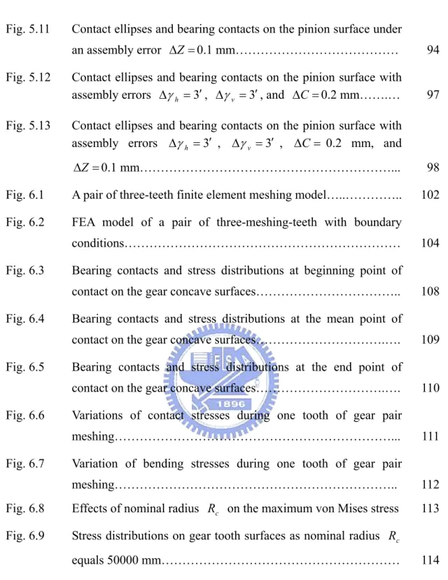
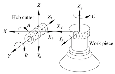
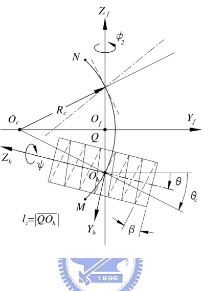
(29) Z. Zf. Xf. X Xh. Y. B. C. Zh. Hob cutter A. Yf. Work piece. Yh. Fig. 2.1 A schematic drawing of a 6-axis CNC hobbing machine. 2.2 Generation Method for Curvilinear-Tooth Gears Figure 2.1 depicts a schematic drawing of a 6-axis CNC hobbing machine, where axes X, Z, and Y represent the functions of the radial feed, axial feed, and hob shift of the hob cutter, respectively; axes A, B, and C are the hob’s swivel axis, hob’s spindle axis, and worktable axis, respectively. Some axes of the CNC hobbing machine are fixed while some axes are rotated with a specific relationship during the gear manufacturing process. For example, in the manufacturing of helical and spur gears, axes X and A are fixed and in the manufacturing of worm gears, axes A, X, and Z are fixed. Figure 2.2 illustrates the generating method of a curvilinear-tooth gear cut by hob cutters. Axes Z h and Z f are the rotation axis of hob cutter and work piece, respectively. Point O f is located on the middle section of a work piece width. Oh. -11-.
(30) Zf 2. N. Rc. Oc. Of. Yf. Q Zh Oh c. M. Sz= QOh. Yh. Fig. 2.2 Generating method of a curvilinear-tooth gear cut by hob cutters. ︵ denotes the rotational center of the hob’s swivel. Circular-arc MN stands for the. tooth trace of a curvilinear-tooth gear, Oc indicates the curvature center of circular ︵ arc MN , and Rc represents the nominal radius of the circular arc tooth trace.. In addition to a rotation motion about axis Z h for the hob’s spindle, the rotation center of the hob’s swivel Oh translates along axis Z f and the swivel axis rotates about point Oh .. The rotational angle of the hob’s swivel and the axial feed. displacement motion are designated by θ and l z , and they are related by the equation: -12-.
(31) l z = QOh = Rc sin θ c = Rc sin(θ + β ) ,. (2.1). where β is the lead angle of the hob cutter, and θ c = θ + β as shown in Fig. 2.2. Differentiating Eq. (2.1) with respect to time, the relationship between the linear velocity of axial feed motion Vz and the angular velocity of hob’s swivel ω A =. dθ dt. can be expressed as follows:. d lz k f = −ω A Rc cos(θ + β )k f . dt. Vz = −. (2.2). The rotational angles between the work piece and hob can be represented as follows:. φ2 =. T1 ψ + Δφ2 . T2. (2.3). where φ 2 and ψ denote rotational angles of the work piece and the spindle of hob cutter.. T1 and T2 are the numbers of threads of the hob cutter and the number of. teeth of the generated gear, respectively. Δφ2 represents an additional angle of work piece rotation due to the feed motion of the hob.. According to Fig. 2.2, the. additional angle for cutting curvilinear-tooth gears can be represented by: Δφ2 =. Rc (1 − cos(θ + β )) , r2. (2.4). where r2 indicates the radius of operating pitch cylinder of the work piece. Differentiating Eq. (2.3) with respect to time, then the relationship among the angular velocities ω A , ω B , and ω 2 can be obtained as follows:. ω2 =. R sin(θ + β ) dφ2 T1 = ωB + c ωA , dt T2 r2. where ω B =. (2.5). dψ . Equation (2.5) represents the work piece rotation ω 2 in terms of dt. -13-.
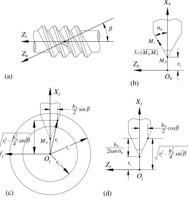
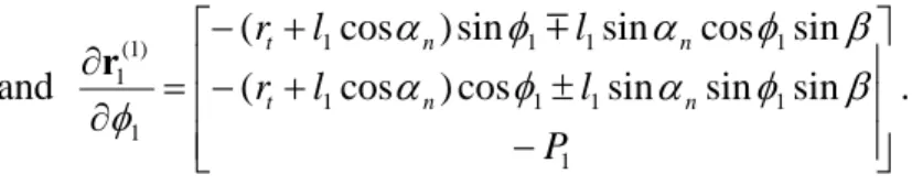
(32) two independent variables ω A and ω B .. To generate the curvilinear-tooth gear by a. hob cutter, axes A, B, C, and Z of a hobbing machine must be controllable in the process of gear generation.. 2.3 Equation of the Hob Cutter The axial profile of the ZA worm-type hob and the normal profile of the ZN worm-type hob are in straight-lined shapes. These types of hobs are easier to manufacture the profiles at axial or normal section with straight-lined shapes. Therefore, the ZA worm-type or ZN worm-type hobs are chosen instead of the ZI worm-type hob for generation of involute gears. The ZN worm-type hob cutter is widely used in the gear manufacturing. A right-hand ZN worm-type hob cutter is used to simulate the manufacture of curvilinear-tooth gears in this study. The surfaces of the hob cutter can be generated by a blade with the straight lined shape, performing a screw motion with respect to the rotational axis of hob cutter. The cutting blade is installed on the groove normal section of the ZN-type worm, as shown in Fig. 2.3(a). Parameter β designates the lead angle of the worm. The generating lines can be represented in the coordinate system Sb ( X b , Yb , Z b ) that is rigidly connected to the blade, as shown in Fig. 2.3(b), expressed by:. rb( B ). ⎡rt + l1 cos α n ⎤ ⎥ ⎢ 0 ⎥, ⎢ = ⎢ ± l1 sin α n ⎥ ⎥ ⎢ 1 ⎦ ⎣. (2.6). where symbol l1 is one of the design parameters of the. straight-lined cutting blade. surface which represents the distance measured from the initial point M o , moving. -14-.
(33) Xb. 1. Z. n. M1. S1 = M 0 M 1. Zb. Zb. M0. (a). rt. Ob. (b) X1 X1. bn sin 2. bn cos 2. 2. 2 r12 b n sin 4. Y1. M0. r1. bn 2tan. ro. O1. rf. Z1. 2. 2 r12 b n sin 4. n. rt. O1. (c). (d). Fig. 2.3 Geometry of the straight-edged cutting blade and worm-type hob cutter. -15-.
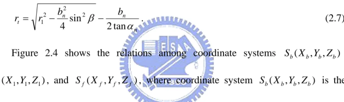
(34) along the straight line M o M 1 , to any point M 1 on the X b − Z b section of the cutting blade surface. Design parameter α n symbolizes the blade’s half apex angle formed by the straight-lined blade and X b -axis, as illustrated in Fig. 2.3(b). In Eq. (2.6), the upper sign represents the left-side cutting blade while the lower sign indicates the right-side cutting blade. In Fig. 2.3(c), the symbols ro , r1 , and r f represent the outside radius, pitch radius, and root radius of the ZN worm-type hob cutter, respectively. The cutting blade width bn equals the normal groove width of the hob cutter, and the design parameter rt can be obtained from Fig. 2.3(c) and (d) as follows: rt = r12 −. bn2 bn . sin 2 β − 4 2 tan α n. (2.7). Figure 2.4 shows the relations among coordinate systems Sb ( X b , Yb , Z b ) , S1 ( X 1 , Y1 , Z1 ) , and S f ( X f , Y f , Z f ) , where coordinate system Sb ( X b , Yb , Z b ) is the. blade coordinate system, coordinate system S1 ( X 1 , Y1 , Z1 ) is rigidly connected to the hob cutter’s surface, and coordinate system S f ( X f , Y f , Z f ) is the reference coordinate system. Axes Z b and Z f form an angle β that is equal to the lead angle on the worm pitch cylinder as shown in Fig. 2.4(a). Figure 2.4(b) shows that the movable coordinate system S1 ( X 1 , Y1 , Z1 ) performs a screw motion with respect to the fixed coordinate system S f ( X f , Y f , Z f ) along the rotational axis of the hob cutter, Z1 -axis. The locus of the cutting blade can be represented in coordinate system. S1 ( X 1 , Y1 , Z1 ). by. applying. the. transformation matrix equation:. -16-. following. homogeneous. coordinate.
(35) Xb , X f Zb Zf Ob,O f. Yb Yf (a) Relationship between coordinate systems Sb and S f. X1 Z f , Z1. 1. Xf. O1. Of. O f O1 = P1. 1. Yf. Y1. (b) Relationship between coordinate systems S1 and S f. Fig. 2.4 Relations between the hob cutter and cutting blade coordinate systems. -17-.
(36) r1(1) = M1 f M fb rb( B ) ,. 0 ⎡1 ⎢0 cos β where M fb = ⎢ ⎢0 sin β ⎢ 0 ⎣0. and M1 f. (2.8) 0 − sin β cos β 0. ⎡ cos φ1 sin φ1 ⎢− sin φ cos φ 1 1 =⎢ ⎢ 0 0 ⎢ 0 ⎣ 0. 0⎤ 0⎥⎥ , 0⎥ ⎥ 1⎦. 0 0 ⎤ 0 0 ⎥⎥ , 1 − P1φ1 ⎥ ⎥ 0 1 ⎦. where P1 denotes the lead-per-radian revolution of the hob cutter’s surface, and φ1 indicates the rotational angle of the hob cutter in relevant screw motion. Substituting Eq. (2.6) in to Eq. (2.8), the surface equation of the ZN worm-type hob cutter r1(1) , represented in coordinate system S1 ( X 1 , Y1 , Z1 ) , can be expressed as: ⎡ (rt + l1 cos α n ) cos φ1 m l1 sin α n sin φ1 sin β ⎤ ⎢− (r + l cos α ) sin φ m l sin α cos φ sin β ⎥ n 1 1 n 1 (1) ⎥, r1 (l1 , φ1 ) = ⎢ t 1 ⎥ ⎢ ± l1 sin α n cos β − P1φ1 ⎥ ⎢ 1 ⎦ ⎣. (2.9). where l1 and φ1 are the surface parameters of the hob cutter. In Eq. (2.9), the upper sign represents the right-side hob cutter surface while the lower sign indicates the left-side hob cutter surface. The surface normal vector N1(1) of the hob cutter can be obtained and represented in coordinate system S1 ( X 1 , Y1 , Z1 ) as follows: N1(1) =. ∂r1(1) ∂r1(1) , × ∂l1 ∂φ1. (2.10). ⎡ cos α n cos φ1 m sin α n sin φ1 sin β ⎤ ∂r1(1) ⎢ where = ⎢− cos α n sin φ1 m sin α n cos φ1 sin β ⎥⎥ , ∂l1 ⎥⎦ ⎢⎣ ± sin α n cos β. -18-.
(37) ⎡− (rt + l1 cos α n ) sin φ1 m l1 sin α n cos φ1 sin β ⎤ ∂r1(1) ⎢ and = ⎢ − (rt + l1 cos α n ) cos φ1 ± l1 sin α n sin φ1 sin β ⎥⎥ . ∂φ1 ⎥⎦ ⎢⎣ − P1. 2.4 Relative Velocity and Equation of Meshing Between Hob Cutter and Work Piece. Figure 2.5 reveals the schematic relationship among coordinate systems S1 ( X 1 , Y1 , Z1 ) , S h ( X h , Yh , Z h ) , S 2 ( X 2 , Y2 , Z 2 ) , and S f ( X f , Y f , Z f ) for the gear. generation mechanism. Coordinate system S1 ( X 1 , Y1 , Z1 ) is attached to the hob cutter while coordinate system S 2 ( X 2 , Y2 , Z 2 ) is attached to the gear blank. Coordinate system S h ( X h , Yh , Z h ) is the reference coordinate system and coordinate system S f ( X f , Y f , Z f ) is the fixed coordinate system attached to the machine housing.. Symbols. ψ and φ2 are rotational angles of the hob cutter and gear blank,. respectively. θ depicts the rotational angle of hob’s swivel axis. The homogeneous coordinate transformation matrix M ij. transforms the. coordinates from coordinate system S j ( X j , Y j , Z j ) to Si ( X i , Yi , Z i ) . According to the relations as illustrated in Fig. 2.5, matrices M h1 , M fh , and M 2 f can be obtained as follows: ⎡cosψ ⎢ sin ψ M h1 = ⎢ ⎢ 0 ⎢ ⎣ 0. − sin ψ cosψ 0 0. 0 ⎡− 1 ⎢ 0 − sin θ M fh = ⎢ ⎢ 0 − cosθ ⎢ 0 ⎣0. 0 0⎤ 0 0 ⎥⎥ , 1 lh ⎥ ⎥ 0 1⎦. 0 − cosθ sin θ 0. (2.11). lx ⎤ 0 ⎥⎥ , − lz ⎥ ⎥ 1 ⎦. -19-. (2.12).
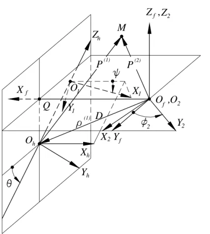
(38) Z f , Z2 M. Zh P. (1). O1. Xf Q. P. (2). X1. Y1 (1). Of ,O2. D 2. Y2. X2 Yf. Oh Xh Yh. Fig. 2.5 Coordinate systems of the hob cutter and CNC hobbing machine. -20-.
(39) and M 2 f. ⎡ cos φ 2 ⎢− sin φ 2 =⎢ ⎢ 0 ⎢ ⎣ 0. sin φ 2 cos φ 2 0 0. 0 0 1 0. 0⎤ 0⎥⎥ , 0⎥ ⎥ 1⎦. (2.13). where lh = O1Oh , l x = O f Q , and l z = QOh . In Fig. 2.5, point M is a common point to both hob cutter and work piece. The surface coordinates of the hob cutter can be transformed to the fixed coordinate system S f ( X f , Y f , Z f ) as follows: P ( 2) = O f M = M fh M h1r1(1) = x f i f + y f j f + z f k f .. (2.14). The velocity of point M attached to the work piece can be obtained by: V f( 2) = ω 2 × P ( 2) = − y f ω 2 i f + x f ω 2 j f ,. (2.15). where ω 2 = ω 2k f indicates the angular velocity of the work piece. The velocity of point M attached to the hob cutter can be represented as follows: V f(1) = (ω A + ω B ) × P (1) + Vz ,. (2.16). where ω A = −ω Ai f , ω B = −ω B cosθ j f + ω B sin θ k f , P (1) = P ( 2 ) − (l x i f − l z k f ) = ( x f − l x )i f + y f j f + ( z f + l z )k f .. and Vz was expressed in Eq. (2.2). After some mathematical operations, Eq. (2.16) can be simplified as follows:. V. (1) f. ⎡ ⎤ − ( z f + l z )ω B cosθ − y f ω B sin θ ⎢ ⎥ =⎢ ( x f − l x )ω B sin θ + ( z f + l z )ω A ⎥. ⎢− y f ω A + ( x f − l x )ω B cosθ − Rcω A cos(θ + β )⎥ ⎣ ⎦. (2.17). Based on Eqs. (2.15) and (2.17), the relative velocity V f(12 ) represented in coordinate system S f ( X f , Y f , Z f ) can be expressed by:. -21-.
(40) V f(12 ) = V f(1) − V f( 2) ⎡ − ( z f + l z )ω B cosθ − y f ω B sin θ + y f ω 2 ⎤ ⎥. ⎢ =⎢ ( x f − l x )ω B sin θ + ( z f + l z )ω A − x f ω 2 ⎥ ⎢− y f ω A + ( x f − l x )ω B cosθ − Rcω A cos(θ + β )⎥ ⎦ ⎣. (2.18). Equation (2.18) shows the relative velocity of hob cutter and work piece at their common point M .. At the common contact point, the common surface normal N (f1). is perpendicular to the relative velocity V f(12 ) . Therefore, the following equation must be observed [12,13]: N (f1) ⋅ V f(12 ) = 0 .. (2.19). Equation (2.19) is the equation of meshing of the gear and hob cutter. This equation guarantees the tangency of the hob and gear at any instant during the gear generating process. Substituting Eqs. (2.10) and (2.18) into Eq. (2.19) yields:. (−( z f + l z )ω B cosθ − y f ω B sin θ + y f ω 2 )nxf + (( x f − l x )ω B sin θ + ( z f + l z )ω A − x f ω 2 )n yf + (− y f ω A + ( x f − l x )ω B cosθ − Rcω A cos(θ + β ))nzf = 0 ,. (2.20). where nxf , n yf , and nzf symbolize the components of the unit normal vector. Substituting Eq. (2.5) into Eq. (2.20) and rearranging in terms of two independent variables, ω A and ω B , yields the following equation:. ω B [(−( z f + l z ) cosθ − y f sin θ + y f + ( x f − l x ) cosθnzf ] + ω A [ y f. T1 T )nxf + (( x f − l x ) sin φ A − x f 1 )n yf T2 T2. Rc sin(θ + β ) R sin(θ + β ) nxf + ( z f + l z − x f c )n yf r2 r2. (2.21). + (− y f − Rc cos(θ + β ))nzf ] = 0 .. Since ω A and ω B are independent variables, two equations of meshing are obtained and represented in coordinate system S f ( X f , Y f , Z f ) as follows:. -22-.
(41) f (l , φ ,θ ,ψ ) = n ⋅ V (12,θ ) = y f + ( z f + lz − x f. Rc sin(θ + β ) r2. Rc sin(θ + β ) r2. nxf (2.22). )n yf + (− y f − Rc cos(θ + β ))nzf = 0.. g (l , φ ,θ ,ψ ) = n ⋅ V (12,ψ ) = (−( z f + l z ) cosθ − y f sin θ + y f. T1 )nxf T2. T + (( x f − l x ) sin θ − x f 1 )n yf + ( x f − l x ) cosθ nzf = 0. T2. (2.23). Equations (2.22) and (2.23) are the equations of meshing that relate the hob cutter’s surface parameters to the cutting motion parameters.. 2.5 Mathematical Model of the Curvilinear-Tooth Gear The surface equation of the curvilinear-tooth gear is derived as the envelope to the two-parameter family of hob thread surfaces. The locus of hob cutter surface, expressed in coordinate system S 2 ( X 2 , Y2 , Z 2 ) , can be obtained by applying the following homogeneous coordinate transformation matrix equation: r2( 2 ) = M 2 f M fh M h1r1(1) .. (2.24). According to the gear theory [12], the mathematical model of the generated gear tooth surfaces is the combination of the equation of meshing and the locus of hob cutter surfaces. Hence, the mathematical model of the gear tooth surfaces can be obtained by considering Eqs. (2.22), (2.23), and (2.24), simultaneously.. 2.6 Computer Graphs of the Curvilinear-Tooth Gear The tooth surface equation proposed herein for curvilinear-tooth gears can be verified by plotting the gear profile.. The coordinates of the curvilinear-tooth gear. surface points can be calculated by solving the developed gear mathematical model using numerical methods.. -23-.
(42) Table 2.1 Major design parameters for cylindrical gears with circular arc tooth traces Hob cutter Curvilinear-tooth gear Number of teeth 1 25 Normal module 3 mm 3 mm 25° 25° Normal pressure angle 2.866° ━ Lead angle ━ Face width 60 mm Nominal radius of circular ━ 100 mm arc tooth trace Pitch radius 30 mm 37.5 mm Outside diameter 67.5 mm 81 mm. Fig. 2.6 Computer graph of the curvilinear-tooth gear. -24-.
(43) Table 2.1 lists some major design parameters of a curvilinear-tooth gear. Based on the developed gear mathematical model, a three-dimensional tooth profile of the curvilinear-tooth gear is plotted as displayed in Fig. 2.6.. The figure shows that the. right- and left-side tooth surfaces of a curvilinear-tooth gear are convex and concave teeth, respectively.. 2.7 Surface Deviations of Curvilinear-Tooth Gear The gear design parameters are chosen the same as those listed in Table 2.1. Figure 2.7 shows the tooth profiles of the curvilinear-tooth gear generated by nominal radii of circular arc tooth trace Rc =100 mm, 120 mm, and 200 mm at the cross section Z 2 =0 mm and Z 2 =30 mm, respectively. The tooth profiles generated by a hob cutter with different nominal radii of circular arc tooth trace are the same at the cross-section Z 2 =0 mm as illustrated in Fig. 2.7(a).. The proposed curvilinear-tooth. gear can be viewed as the gear with a varying helical angle across the whole face width, and the helical angle at the cross section Z 2 =0 mm is zero. Therefore, the tooth profiles of the curvilinear-tooth gear generated by different Rc at cross section Z 2 =0 mm is the same as that of spur gears. The results illustrated in Fig. 2.7(a). verify that the mathematical models proposed herein are correct.. Figure 2.7(b). shows the tooth profiles generated by a hob cutter with different Rc are not the same at the cross section Z 2 =30 mm. Figure 2.8 reveals the transverse chordal thickness deviations of the curvilinear-tooth gear generated by nominal radii of circular arc tooth trace Rc =100 mm, 120 mm, and 200 mm, respectively. It is found that the transverse chordal thickness at the middle section of face width, i.e., tc =4.709 mm, is larger than those -25-.
(44) at other sections.. A smaller Rc results in a smaller transverse chodal thickness at. the ends of face width as shown in Fig. 2.8. Figure 2.9 illustrates the relationship between the Z 2 component of the tooth cross section and the tooth thickness at the addendum circle, ta . It reveals that the tooth thickness at the middle section of face width, i.e., ta =1.599 mm, is smaller than those at other sections, and a smaller Rc induces a larger tooth thickness ta at the ends of face width. The tooth thickness of the curvilinear-tooth gear generated by hob cutters with different nominal radii of circular arc tooth trace are the same at the middle section of the tooth flank, i.e., Z 2 =0 mm. The analysis results shown in Figs. 2.8 and 2.9 indicated that the deviation of tooth thicknesses, tc and ta , at the both ends of the face width decreased when the nominal radius of circular arc tooth trace Rc is increased. It is noted that the herringbone gears are in line contact, however, the curvilinear-tooth gear pair proposed herein is in point contact. Therefore, the advantage of the proposed gear pair is not sensitive to the axial misalignments. According to the analysis result shown in Fig. 2.8, the curvilinear shapes of the teeth are similar to those of crowned gear tooth surfaces. Thus, the phenomenon of gear edge contact of the curvilinear-tooth gears can be avoided.. 2.8 Remarks The mathematical model of curvilinear-tooth gears has been developed on the basis of the CNC hobbing machine cutting mechanism and the gear theory. The model is represented as a function of hob cutter design parameters and generating motion parameters. The developed mathematical model provides the industry with an. -26-.
(45) 8 (mm). 6. Pitch circle. 4. 2. 0. R c =100 mm R c =120 mm R c =200 mm. 2. 4. 6. 8 (mm). (a) Tooth profile at cross section Z 2 =0 mm. 8 (mm). 6. Pitch circle. 4. 2. 0. R c =100 mm R c =120 mm R c =200 mm. 2. 4. 6. 8 (mm). (b) Tooth profile at cross section Z 2 =30 mm. Fig. 2.7 Different tooth profiles of the curvilinear-tooth gear generated by Rc =100 mm, 120 mm and 200 mm -27-.
(46) tc. (mm). 4.709. Rc =100 mm Rc =120 mm Rc =200 mm. 4.468. Z2. 0 -30. -20. -10. 0. 10. 20. 30 (mm). Fig. 2.8 Transverse chordal thickness on different cross section. ta. (mm). 2.004 R c =100 mm R c =120 mm R c =200 mm. 1.599. Z2 -30. -20. -10. 0. 10. 20. 30 (mm). Fig. 2.9 Thickness of tooth at addendum circle on different cross section. -28-.
(47) efficient method to design and manufacture curvilinear-tooth gears.. The illustrated. approach can be further extended to derive the mathematical model of non-circular face width gears, for example, parabolic or elliptical curved tooth traces. The tooth surface deviations induced by different nominal radii of circular arc tooth traces are also investigated. The transverse gear chordal thickness measured at the middle section is larger than those of other sections, but the tooth thickness at the addendum circle in the middle section of face width is smaller than those of other sections. The developed tooth mathematical model helps to explore the possibility for further investigations, such as sensitivity, kinematic errors and contact stress analyses.. -29-.
數據
+7
相關文件
Students are provided with opportunities to learn and develop the skills, strategies and confidence needed to participate in Guided and Independent Reading as well as the
Wang, Solving pseudomonotone variational inequalities and pseudocon- vex optimization problems using the projection neural network, IEEE Transactions on Neural Networks 17
volume suppressed mass: (TeV) 2 /M P ∼ 10 −4 eV → mm range can be experimentally tested for any number of extra dimensions - Light U(1) gauge bosons: no derivative couplings. =>
Define instead the imaginary.. potential, magnetic field, lattice…) Dirac-BdG Hamiltonian:. with small, and matrix
• Formation of massive primordial stars as origin of objects in the early universe. • Supernova explosions might be visible to the most
For R-K methods, the relationship between the number of (function) evaluations per step and the order of LTE is shown in the following
Finally, adding the discussion of cultural causes and the rise of Rome typeface, the relationship between the gothic script and the renaissance typeface design for the future study
The difference resulted from the co- existence of two kinds of words in Buddhist scriptures a foreign words in which di- syllabic words are dominant, and most of them are the
