Increasing Payload in Reversible Data Hiding Scheme for Image Steganography
Chin-Feng Lee
Department of Information
Management, Chaoyang
University of Technology
[email protected]
Chi-Yao Weng
Department of Computer
Science, National Tsing-Hua
University
[email protected]
Aneesh Sharma
Department of Communication
and Computer Engineering,
LNM Institute of Information
Technology, India
[email protected]
Abstract
Reversible data hiding is the technique that allows embedding (hiding) data in an image and later the hidden data as well as the exact copy of the image can be recovered at the receiver’s end. Two important aspects of reversible data hiding are high quality and good capacity. The distortions to the original signal should be such that artifacts are not visible since these distortions may create problems in some fields such as medical, astronomical, and military images due to legal reasons. To efficiently solve the above-mentioned observations, we propose yet another reversible algorithm that embeds the secret upon the histogram of grayscales of image pixels, where the secret is embedded using the related information near to peak area in histogram. The proposed algorithm removes some extra data which were previously needed as in Ni et al.’s algorithm. Experimental results demonstrate that our proposed algorithm has noticeable capacity improvement when compared to Ni et al.’s algorithm although it has some quality degradation. The stego image quality from proposed method is still quite good and far better than the established standards.
Keywords: Reversible data hiding, histogram modification,
neighbor information, embedding capacity.
1. Introduction
Reversible data hiding is mainly used for the content authentication of multimedia data like images, videos, electronic documents etc. because of its emerging demands in various fields such as medical imagery, law enforcement, astronomical research, etc. One of the most important requirements in this field is to have the original image during judgment to take the right decision. Other synonyms
of reversible scheme are distortion-free, lossless, invertible scheme.
Nowadays, research in reversible data hiding has become quite important. Several reversible data hiding schemes have been proposed. These schemes can be divided according to three approaches: spatial domain [1, 2, 4-8], frequency domain [9, 10], and index-based domain [11, 12].
Recently, some reversible marking techniques have been reported in the literature [3]. The first method is carried out in the spatial domain. It uses modulo 256 addition assuming here that eight-bit grayscale images are considered to embed the hash value of the original image for authentication. The embedding formula is Iw=(I+W) mod 256, in which I denotes the original image, Iw the marked image, and the watermark W = W (H(I), k), where H(I) denotes the hash function operated on the original image I, and the secret key
k. The usage of modulo 256 addition, the over/underflow is
prevented and the reversibility is achieved.
The histogram based reversible data hiding scheme was proposed by Ni et al. in 2006 [1]. The peak and zero pair of the histogram were searched. The peak pixel or zero pixel is so-called ‘point’ meaning pixel-value corresponding to the statistic peak/zero. The pixels between the peak and zero pair were modified in the embedding processing. The pixel in the peak point was used to carry a bit of the secret message. The others were modified and no secret data were embedded. In the histogram-based data hiding, the number of pixels in the peak point is the maximal hiding capacity for the secret message to be embedded and the pair information of peak-point and zero-point needs extra space to be stored. The extra space is kind of some redundant information to downgrade the capacity of embedding secret. In this paper, we proposed a reversible data hiding scheme to improve the embedding capacity in Ni et al. [1].
The idea is to minimize the extra data and leading to increase the embedding points. The scheme uses neighborhood of the peak to store the information instead of a peak and uses the end pixels of the histograms as zero points. This technique reduces the overhead of storing peak and zero pair. Further multiple peaks are used to enhance the capacity. This technique can virtually be applied to all types of images. Up to now, it has been successfully tested on different types of images, including some commonly used images, medical images, texture images and aerial images. The proposed algorithm performs much better on the images with compact histograms than other kind of images. Moreover, the computation of our proposed technique is also quite simple.
The rest of this paper is organized as follows: In Section 2, a histogram-based reversible data hiding proposed by Ni et al. is briefly described. Our contribution is then presented in Section 3. In Section 4, the experimental results are given. Finally, some conclusions are stated in Section 5.
2. Backgrounds
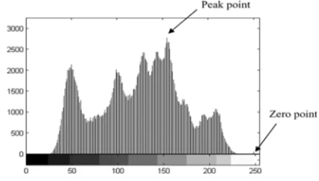
In 2006, Ni et al. [1] proposed a histogram-based reversible data hiding scheme. In their scheme, some of pixel values from the histogram are selected and modified to carry the secret data. The modified pixel values can be recovered when the embedded data is extracted, such that the reversible data hiding is achieved. In the embedding procedure, first of all, the pair of peak-point and zero-point from the image histogram is searched. The peak- point is the pixel value with maximum occurrences in the histogram. The zero-point is the one with zero or minimum occurrences in the histogram. A histogram of a sample image is shown in Figure 1 in which the peak and zero points are also pointed out. In the histogram-based reversible data hiding scheme, pixels lying between the range of peak-point and zero-point need to be modified. Pixels outside the range are left unchanged. The length of the secret data is decided by the number of the peak-points.
Before beginning embedding procedure, the zero pixels are recorded if the value of the histogram zero point is not equal to zero. Accordingly, this extra data is needed to be embedded along with the secret data stream.
The rule for pixel modification is based on the location of pixels in the image histogram. Two scenarios are considered. First, find out the pair of peak-point (P) and zero-point (Z) and keep the pair information for extracting producer. Then, the value of each pixel x, i =1, 2, …., n, is between the
point and zero-point but those not equal to the peak-point is also shifted by 1 closer to the zero-peak-point. For instance, if the value of peak-point is more than value of zero-point, the range of [Z+1, P-1] is shifted by 1; otherwise, the range of [P+1, Z-1] is shifted by 1. Second, the secret bitstream data si, i =1, 2, …., n, is embedded. For each pixel value
x
i=
P
, if the value of si equals 0, the value of xi is kept unchanged; otherwise, the value of xi is adjusted by ±1 to the value. After all pixels in the image histogram are sequentially processed, the stego-image is generated. Finally, the stego-image and the peak and zero points are transmitted to the receiver.In the recovery procedure, the stego-image and the pair information of peak-point and zero-point are required. Each stego-pixel with value x is processed in following manner. i' If 'x is located in the peak-point, 1-bit secret data valued at i
0 is extracted and the value of
x
i'
is unchanged. But, if the absolute difference betweenx
i'
and the peak-point is 1 andit also lied in between peak and zero pair, 1-bit secret data valued at 1 is extracted and the value of
x
'
is replaced by the value of the peak point. Lastly, the range of [Z+1, P-1] or [P+1, Z-1] is shifted by 1 according to the value of peak-point and zero-peak-point that are recorded after data embedding. After that, the embedded secret data is extracted from the stego-image and the original cover image can be exactly restored.Figure 1: Histogram of a sample image
An example of the histogram is shown in Figure 2. In the example, the pair of peak and zero point is (5, 8). From the histogram, there are 6 pixels with value 5.
Figure 2: Original sample histogram
Suppose the secret data (S) is (001010) 2 to be embedded.
Firstly, each pixel value falling within the range [5+1, 8-1] is increased by 1 according to pair information of peak-point and zero-peak-point. Then, we scan the image and when we encounter a pixel with the value 5, then, we will look up the
ith secret bit (si), if si is 0 then the pixel is kept intact. Otherwise, the pixel value is shifted to the right by ‘1’ unit. When the pixel values are not equal to 5, then no secret data are embedded in and the pixel value is unchanged. The resulting histogram can be seen in Figure 3 after secret data is embedded.
Figure 3: Stego histogram
The final stego-image is quite similar to the original cover in this scheme. This is because only pixels with their values within the range from the peak-point to the zero-point are modified. In addition, the modification of the pixel value is
less than or equal to 1. Also, the pixels with their values outside the range are not to be modified.
The hiding capacity of the histogram-based data hiding is limited in the number of pixels in the peak-point. To increase the hiding capacity, more number of peak and zero pairs can be used. Sometimes, it is difficult to find out more pairs of peak and zero points because of the unavailability of zero points, and need more extra data to keep the pairs information for exactly extracting secret bits. The bin (the x-axis in histogram) with the min histogram value is usually selected as the zero-point. If the value of histogram at zero- point is not equal to zero then we have to store the information of the pixels at zero-point. In this scheme, to recover the image the pair of peak-point and zero-point must be recorded and that is the overhead/extra data. Large overhead reduces the actual embedding capacity of the image.
3. The Proposed Scheme
The proposed scheme takes full advantage of neighbor information around the peak-point to embed the data instead of the peak-point itself. Hence, it increases the embedding sites. The goal of the proposed scheme is to provide a higher hiding capacity while keeping the good quality of the stego-image.
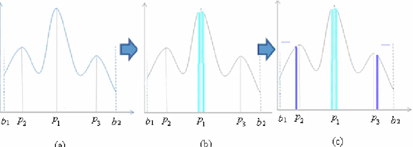
To enlarge the hiding capacity of the histogram-based scheme, multiple peak-points are searched. Secret data are then embedded in the neighborhood information of the peak-points by using a modified histogram-based approach. The proposed scheme consists of two procedures: the secret embedding procedure and the secret extraction and image recovery procedure. An overview of the proposed secret embedding is shown in Figure 4. The light blue and blue colors indicate the pixels where the secret data will be embedded.
Figure 4: The embedding procedure of proposed scheme: (a) original histogram; (b) embedding secret data in the neighbors of maximum peak; (c) embedding secret data in the neighbors of second peaks.
3.1 Embedding procedure
Secret data is embedded in the pixels which have value equal to the either neighbor of the bin with peak-point. This approach increases the embedding capacity of the histogram while maintaining the image quality. The performance of this approach increases as the compactness of the histogram increases.
To embed the secret data, firstly the histogram (H(x)) of the cover image is generated. The secret data is embedded in the pixels with value equal to the either neighbors of the peak-points in the histogram. Multiple peak-points are further used to increase the capacity. In this paper, we use 3-peak-points as an example, and our proposed technique can further be extended to n multi-peak-points.
The pseudo-code of the embedding procedure with 3-peak histogram points for an M × N image, each grayscale value
] 255 , 0 [ ∈ i x is as follows:
(1.) Generate histogram H(x) from whole cover image. (2.) In the histogram, find out 3 peak-points: h(p1), h(p2)
and h(p3) where p1, p2, p3 ∈[0,255] such that
h(p1)>h(p2), h(p1)>h(p3) and p2< p1< p3. The
example is depicted in Figure 4.
(3.) The zero-points are the leftmost (h(b1)) and rightmost
(h(b2)) points of the histogram where b1 < b2. Note, if
b1 = 0 or b2 = 255, record all the coordinate (i, j) of
those pixels, which pixel grayscale value is b1 or b2,
as overhead bookkeeping information.
(4.) Move the right part of the histogram H(x) with
x
∈
[p1+2, b2-1] to the right by one unit. This step
makes each right-shift pixel have the grayscale value
∈
x
[p1+3, b2]. Another left part of the histogramH(x) with
x
∈
[b1+1, p1-2] is also moved to the leftby one unit. Afterward, each pixel of this part has the value whose grayscale value
x
∈
[b1, p1-3].(5.) Scan the image to process the pixel with grayscale value xi, i ∈1, 2, …., M×N, and run the following sub-steps.
(5.1) When pixel value xi=p1−1 and the secret bit
to be embedded is “1”, the pixel grayscale value xi is changed to be “xi-1”; otherwise, when the pixel value xi =p1−1 and the secret
bit to be embedded is “0”, the grayscale value
xi remains unchanged.
(5.2) In case of pixel value xi =p1+1, if the secret
bit is “1” then the pixel grayscale value is changed to “xi+1”. Otherwise, if the secret bit is “0”, then the grayscale value xi remains unchanged.
(5.3) Considering the pixel value xi ≠p1±1, we do nothing and keep the pixel value xi as unchanged.
The newly generated histogram H' x( )can be used to embed more data as following steps.
(6.) Look for the peak points p and 2' p respectively in 3'
the left and right part of the peak (p1) and the
zero-points b1'and 'b of the histogram where 2 b1'<b2'. (7.) Move a part of the histogram H' x( ) with pixelx∈
] 1 ' , 2 '
[p3+ b2− to the right by 1 unit. This means all the pixels with grayscale values fall within the range
] ' , 3 '
[p3+ b2 . Another part of the histogram H' x( )
with pixel
x
∈
[b1'+ p1, 2'−2] is moved to the left by 1 unit such that the values of this part lie in the range1 2
[ ',b p ' 3]− . The second data segment can be embedded using the following sub-steps:
(7.1) In case of pixel value xi =p2' 1− , if the secret
changed to be“xi - 1”, otherwise, the grayscale value xi will remain unchanged. (7.2) In case of pixel value xi=p3' 1+ , if the secret
bit is “1” then the pixel grayscale value xi is changed to be“xi+1”, if the secret bit is “0” then the grayscale value xi remains unchanged. (7.3) In case of pixel value xi≠p2' 1− or xi ≠p3' 1+ .
Nothing to do and the pixel value is kept as unchanged.
(8.) The final generated histogram of the stego-image is known as H' x'( ).
The above method requires more compact histogram as it relies on the neighbors of peak-points to embed data. So, the method achieves greater performance when applied to the difference histogram. Since, the difference histograms are more compact than the original.
The scheme uses neighbor of the peak-point to embed the data instead of peak-point, therefore, no extra data or overhead information is needed to keep track of peak and zero pairs.
3.2 Extraction procedure
To recover the cover image and secret data, the extracting scheme is an inverse operation of the embedding scheme except for image coming form stego-image. The pseudocode algorithm is shown as follows.
(1.) Generate the histogram H'' x( ) of the stego-image.
(2.) In the histogram, find out 3 peak-points: h(p1'') , )
'' (p2
h and h(p3'') such that h(p1'')>h(p2'') ,
) '' ( ) '' (p1 h p3 h > , where p1'',p2'',p3'' ∈[0 ,255] and '. ' '' '' 1 3 2 p p p < <
(3.) The leftmost and rightmost end points of the histogram are considered as zero-points b1'' and b2'', respectively.
(4.) Scan the stego-pixel with grayscale value x , i =1, i' 2, …., M×N, and run the following sub-steps for extracting message and recovering the image.
(4.1) If pixel value x'i =p2'' 2− , the secret bit “1” is extracted and the pixel grayscale value x is i' changed to be “ xi'+1 ”. If pixel value
1 '' '= p2 −
xi then the secret bit “0” is extracted and the pixel grayscale value xi' remains
unchanged.
(4.2) If pixel value xi'= p3''+2 then the secret bit “1” is extracted and the pixel grayscale value x is i' changed to be “ xi'−1 ”. If pixel value
1 '' '= p3 +
xi , then the secret bit “0” is extracted, and the pixel grayscale value xi' remains unchanged.
(4.3) If the gray value 'x does not satisfy with i
either one of the following four cases as shown below, nothing will be done, and the pixel value is kept as unchanged.
Case 1: xi'≠ p2''−1. Case 2: xi'≠ p2''−2. Case 3: xi'≠ p3''+1. Case 4: xi'≠ p3''+2.
(5.) Move a part of the histogram H '' x( ) with ] ' ' , 2 ' ' [p3 b2
x∈ + to the left by 1 unit. Similarly, another part of the histogram H'' x( ) with
] 2 ' ' , ' ' [ 1 2 − ∈ b p
x is moved to the right by 1 unit. Note, if there is overhead bookkeeping information found in the extracted data, restore the value of the pixel (i,
j) to respective zero-point in the histogram.
(6.) Newly generated histogram H' x( )is used to extract further secret data. Look for the peak-points p and 2'
'
3
p in the left and right part of the peak-point (p1''), and the zero-point are leftmost ( h(b1') ) and rightmost (h(b2')) points of the histogram where
' ' 2
1 b
b < , respectively.
(7.) Rescan the image for the pixels with grayscale values '
i
x , and run the following sub-steps for extracting
message and recovering the image.
(7.1) If pixel value x'i= p1''−2, the secret bit “1” is extracted and then the pixel grayscale value
' i
x is changed to be “xi'+1”. If pixel value 1
'' '= p1 −
xi , the secret bit “0” is extracted and then the pixel grayscale value xi' remains unchanged.
(7.2) If pixel value xi'= p1''+2, the secret bit “1” is extracted and then the pixel grayscale value
' i
x is changed to be “xi'−1”. If pixel value
1 ' '= p1+
xi , the secret bit “0” is extracted and then the pixel grayscale value xi' remains unchanged.
(7.3) If the gray value 'x does not satisfy with the i
conditions of xi'≠ p1''±2and xi'≠ p1''±1, the
pixel value just keeps itself unchanged. (8.) Finally, for the pixel with grayscale value
] 2 '' , ' [1 1 − ∈b p
x , x is increased by 1. For the pixel with grayscale value x∈[p1''+2,b2'], x is decreased by 1. (9.) The final generated histogram of the cover image is
returned as H(x) and the extracted bits are the secret data.
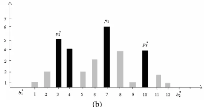
An example of the histogram is shown in Figure 5. In the example, three peak points p1=7, p2=4 and p3=9, and zero
Figure 5: A sample of original histogram.
Suppose that the secret message can be treated as a concatenation of two segments which are 0010010100 and 001001, respectively. The first step shifts the gray values falling within the range [3 (=2+1), 5 (=7-2)] and [9 (=7+ 2),10 (=11 - 1)] into [2, 4] and [10, 11] for embedding secret bits. According to Step 5 of embedding procedure, the first secret data segment with 10 (=5+5) bits will be embedded into the pixels with values equal to 6 (=7-1) and 8 (=7+1) and the result is shown as Figure 6 (a). Further, the modified histogram data will be inserted at the pixels with values 2 (= p2'−1=3−1) and 11 (= p3'+1=10+1); namely, the second secret data segment with 6 (3+3) secret bits will be embedded into the histogram according to Step 7 of embedding producer. Note, all the pixel values lying in the rage of [b1'+ p1, 2'−2](= [1, 1]) and[p3'+ b2, 2'−1] (= [12, 12]) had been shifted into [b1',p2'−3] (= [0, 0]) and
] ' , 3 '
[p3+ b2 (= [13, 13]) before the second data segment is embedded. Finally, the resultant histogram can be seen in Figure 6 (b).
(a)
(b)
Figure 6: The example performances for using proposed procedure: (a) the result of histogram by using maximum peak embedding; (b) stego-histogram by using our scheme.
4. Experimental Results
In our experiments, three grey cover images (Lena, Baboon and Boat) of size with 512 × 512, are shown in Figure 7. Figure 8 shows the histogram of the cover images. In our procedure, secret data is random bits. Figure 9 shows the stego-images by using our proposed scheme along with their histograms. The estimation function of PSNR (peak signal-to-nose ratio) is applied to evaluation the quality of stego-image.
The performance of proposed method depends on the compactness of the histogram. More the capacity of the histogram is more the performance and the results are shown in Table 1. The reason is as described, the hiding procedure uses neighbors of the peak-points so if the histogram is more compact, less number of pixels are needed to be shifted so as to embed the secret data and the extract data is free because the peak-point information are still to be kept. Also, the value of the neighbors will not drop much as compared to the peak-point value and hence, the proposed scheme can hide more data than Ni et al.’s histogram-based scheme [1].
5. Conclusions
In this paper, a reversible data hiding scheme based on using neighbor information of multiple peak-points is presented.Instead of directly embedding secret data into the peak-points of the histogram, the secret data are embedded near the peak-points of the histogram to achieve a higher embedding capacity since the quantities of neighbors near the peak-points are larger than the number of peak points for secret embedding. The proposed scheme increases the hiding capacity by notable amount by small compromise in the PSNR value.
The results show that the proposed reversible data hiding scheme provides a higher hiding capacity while making a small compromise on the image quality of stego-images. That is because of two reasons, first is the increase in number of hiding sites, and second is the reduction in the additional overhead needed for coordination information as
required in Ni et al.’s scheme. Besides, the computational cost of the proposed scheme is very small. Since the embedding algorithm is based on the value of the neighbors of the peak-point, it produces better result when histogram is more compact i.e. difference histogram etc. The application of this algorithm can further be exploited in the residual histogram produced from the difference.
Acknowledgments: This research was partially supported by the National Science Council of the Republic of China under the Grants the NSC 98-2221-E-324-020-
References
[1] Z. Ni, Y.Q. Shi, N. Ansari, and W. Su, “Reversible Data Hiding,” IEEE Transactions on Circuits and
Systems for Video Technology, Vol. 16, No. 3, pp.
354–361, 2006.
[2] P. Tsai, Y. C. Hu, and H. L. Yeh, “Reversible Image Hiding Scheme using Predictive coding and histogram shifting,” Signal Processing, Vol. 89, pp. 1129–1143, 2009.
[3] C. W. Honsinger, P. Jones, M. Rabbani, and J. C. Stoffel, “Lossless Recovery of an Original Image Containing Embedded Data,” US Patent, No. US6278791, Aug. 21, 2001.
[4] C. C. Lin, W. L. Tai, and C. C. Chang, “Multilevel Reversible Data Hiding based on Modification Histogram of Difference Images,” Pattern
Recognition, Vol. 41, pp. 3582–3591, 2008.
[5] H. W. Tseng, and C. P. Hsieh, “Prediction-based Reversible Data Hiding,” Information Sciences, Vol.
41, pp. 2460–2469, 2009.
[6] J. Tian, “Reversible Data Embedding using Difference Expansion,” IEEE Transactions on
Circuits and Systems for Video Technology, Vol. 13,
pp. 890–896, 2003.
[7] A. M. Alattar, “Reversible Watermark using the Difference Expansion of a Generalized Integer Transform,” IEEE Transactions on Image Processing, Vol. 13, No. 8, pp. 1147–1156, 2004.
[8] D. M. Thodi and J. J. Rodriguez, “Expansion Embedding Techniques for Reversible Watermarking,” IEEE Transactions on Image
Processing, Vol. 16, No. 3, pp. 721–7300, 2007.
[9] L. Kamstra and H. J. A. M. Heijjmeans, “Reversible Data Embedding into Images using Wavelet Techniques and Sorting,” IEEE Transactions on
Image Processing, Vol. 14, No. 12, pp. 2082–2090,
2005.
[10] C. C. Chang, C. C. Lin, C. S. Tseng, and W. L. Tai, “Reversible Hiding in DCT-based Compressed Images,” Information Sciences, Vol. 171, pp. 2768– 2786, 2007.
[11] C. H. Yang and Y. C. Lin, “Reversible Data Hiding of a VQ Index Table based on Referred Counts,”
Journal of Visual Communication and Image Representation, Vol. 20, No. 6, pp. 399–407, 2009.
[12] C. C. Chang, Y. P. Hsieh, and C.Y. Lin, “Lossless Data Embedding with High Embedding Capacity Based on Declustering for VQ-Compressed Images,”
IEEE Transactions on Information Forensics and Security , Vol. 2, No. 3 , pp. 341–349, 2007.
(a.) (b.) (c.) Figure 7: Cover images of size 512 x 512: (a.) Lena; (b.) Baboon; (c.) Boat.
(a.) ( b.) (c.) Figure 8: Histogram of the cover images: (a.) Lena; (b.) Baboon; (c.) Boat.
(a.) (b.)
(c.) (d.)
(e.) (f.)
Figure 9: Stego-images : (a.) Lena; (b.)Lena stego-histogram; (c.) Baboon; (d.) Baboon stego-histogram; (e.) Boat; (f.) Boat stego- histogram.
Table 1: Performance comparisons of capacity and PSNR bewteen Ni et al.’s scheme [1] and the proposed scheme
Method Image Capacity(bits) PSNR(dB)
Lena 5,460 48.2 Boat 7,301 48.2 Ni et al.’s scheme [1] Baboon 5,421 48.2 Lena 9,127 45.2 Boat 19,781 45.3 Our scheme Baboon 8,657 45.2

![Table 1: Performance comparisons of capacity and PSNR bewteen Ni et al.’s scheme [1] and the proposed scheme](https://thumb-ap.123doks.com/thumbv2/9libinfo/8915765.261323/8.892.266.626.372.885/table-performance-comparisons-capacity-bewteen-scheme-proposed-scheme.webp)
