Design and Evaluation of Light Spread Function for
Area-Adaptive LCD System
Yu-Kuo Cheng, Yen-Hsing Lu, Chung-Hao Tien, and Han-Ping Shieh, Fellow, IEEE
Abstract—A methodology, based on two-dimensional
super-Gaussian light spread functions (LSFs), was studied for the light-emitting-diode (LED) backlighting system in the high dy-namic range (HDR) liquid crystal displays (LCDs). We proposed a novel LED-based optomechanical configuration to implement the desirable luminous pattern. A dual-liquid-crystal-panel system was constructed as a pseudo-HDR LCD to evaluate the super-Gaussian illumination. The proposed HDR scheme was verified via the current platform: overall luminance uniformity, contrast ratio and processing speed could be improved by factors of 1.55, 1.95–4.15, and 4.82, respectively. The design flexibility made the methodology applicable to any panel dimension and backlight division of the HDR LCDs, and to the conventional full-on backlighting LCDs as well.
Index Terms—Light spread function (LSF), local-dimming
back-light, high dynamic range liquid crystal display (HDR LCD).
I. INTRODUCTION
M
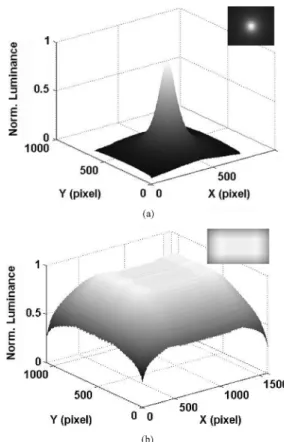
ANY studies have been addressed on the implemen-tation of a high dynamic range (HDR) liquid crystal display (LCD) [1] in various subjects such as optomechan-ical setup, image process algorithm, empiroptomechan-ical testing, etc [2]–[4]. However, the discussion will be incomplete without considering a practical but unique issue: the impact of the luminous distribution of the area-adaptive lighting scheme in the backlighting system of the HDR LCDs. The free-spreading or Gaussian-shaped light spread function (LSF), for instance, is regarded tacitly as the primitive LSF, which can provide convenience in the processes of light-emitting diode (LED) driving signal, LC compensation signal, etc. However, due to the optomechanical limitations, the free-spreading LSF, as shown in Fig. 1(a), for example, may lead to several impacts on the system performance. First, the accuracy of compensated LC signals will deteriorate as the backlight module is not a spatially shift-invariant system. Second, the overall backlight uniformity, as shown in Fig. 1(b), is in general not as uniform as the conventional full-on backlight, which is treated as an entirety so the optomechanical layout can be optimized. Finally, the computational consumption and processing algorithm areManuscript received April 22, 2008; revised July 14, 2008. Current version published January 28, 2009. This work was supported in part by National Sci-ence Council, Taiwan, under Contract NSC 96-2221-E-009-114-MY3 and by Ministry of Economic Affair, Technology Development Program for Academia, the Republic of China, under Contract 96-EC-17-A-07-S1-046.
The authors are with the Department of Photonics & Institute of Electro-Optical Engineering, National Chiao Tung University, 1001 University Road, Hsinchu 300, Taiwan (e-mail: [email protected]).
Color versions of one or more figures are available online at http://ieeexplore. ieee.org.
Digital Object Identifier 10.1109/JDT.2008.2004279
Fig. 1. Intensity distributions of the Gaussian LSF of (a) single light source and (b) the overall panel area, which is computed using convolution calculation with the Gaussian LSF as the impulse response function. Overall intensity dis-tribution is, in general, decreased from the center toward the panel edges.
strongly relevant to the size of the LSF and to the compensation of the undesirable luminous variation.
In this paper, a feasible methodology, based on a moderate LSF, is proposed to solve the aforementioned issues. Ideally, a rectangular LSF is supposed to be the optimized choice in the systematic point of view [5], [6]; however, perfect rectangular luminous distribution is not possible to be realized via current state-of-the-art backlit setup. The super-Gaussian LSF, instead, is a reasonable approximation to the ideal one. Therefore, the procedures are introduced to define, optimize, and realize the desired LSF, which is implemented in a pseudo-HDR platform, a dual-liquid-crystal-panel (DLCP) system. Some system pa-rameters are then measured on the platform to verify the ap-plicability of the proposed design.
II. LGUOFSUPER-GAUSSIANLSF
A. Design Flow
The applicable super-Gaussian light spread functions (LSFs) can be attained via two successive assessments along a
CHENG et al.: DESIGN AND EVALUATION OF LSF FOR AREA-ADAPTIVE LCD SYSTEM 67
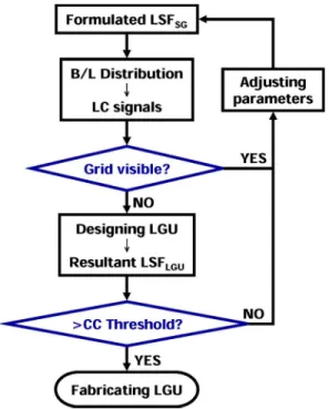
Fig. 2. The flow chart of optimization process, via the DLCP system, for de-termining adequate super-Gaussian LSFs.
ical design flow. The design flow, as shown in Fig. 2, is com-menced with a formulated LSF, denoted as expressed by (1) (see Section II-B), which is then applied to the DLCP system (see Section III-A) to simulate the resultant backlight distribution. The initial values of the parameters A and in (1) are deduced according to the panel dimension and the number of backlight division. The undesirable grid pattern, detrimental to the implementation of super-Gaussian LSF method, arises from the superposition of the tail intensity beyond the flat-topped re-gion across the adjacent backlight divisions. The first assess-ment, therefore, is to perceptually judge the visibility of the grid lines. A set of qualified , obtained by iteratively adjusting the parameters in (1) to make grid pattern invisible as illustrated in Fig. 3(a) and (b), is treated as the target for designing the op-tomechanical part, the light guide unit (LGU) (Section II). The similarity, calculated by the correlation coefficient (CC) (Sec-tion II.D) between the qualified and the emitting light profile of the LGU, denoted as , is the second assess-ment to ensure the acceptability of designed LGU. Finally, the qualified LGU will be fabricated and pieced together to form the complete backlighting system for the HDR LCD.
B. Mathematical Framework
The general formation of a square super-Gaussian light spread function, (x,y), can be expressed as (1) [7], [8]
(1)
where is the maximum luminance value at the center, and and roughly represent the dimensions of the in and directions, respectively. Particularly, the initial values of
and are determined by the quotient of panel resolution divided by the number of backlight partition. The dimension-less parameters, and , determine the edge decay from the central region. A cross-section family of super-Gaussian LSFs, being of identical luminance power with different values of A and p, is illustrated in Fig. 4. As the value of p is approaching to infinity, the (x,y) will change into an ideal rectangle function with the width of and in and directions, respectively. Finally, after perceptual judgment of grid pattern visibility, the set of qualified is treated as the designated light profile for optomechanical design.
C. Optomechanical Configuration
We proposed a novel optomechanical layout, LGU, whose light spreading profile, denoted as , was subject to the qualified . The LGU consisted of three major compo-nents: a side-emitting LED, a quadratic light guide (QLG), and a concentric prismatic sheet (CPS), as shown in Fig. 5. About 80% luminous flux from the side-emitting LED was confined within 20 deg in the azimuthal direction [9]. The LED was located at the cavity center of a QLG, which was mainly facil-itated to redirect the azimuthal flux into the normal direction of the backlight surface. Each QLG unit featured a set of cen-tric micro prismatic bumps on the bottom coated with highly reflective material, silver (Ag), underneath. The set of concen-tric prismatic bumps was arranged in parallel with increasing pitches and heights away from the LED. Detailed optical ray tracing scheme could refer to the literatures [10], [11]. A con-centric prismatic sheet (CPS) was employed to further collimate the divergent light from QLG toward the surface normal. The prismatic structure not only enhanced the optical throughput but kept the nearly square shape illuminating the front LC panel. The structure of a CPS was identical to that of the conventional prismatic sheet by 3M™ [12], merely in the concentric arrange-ment.
Based on the proposed configuration of CPS and QLG, the luminous flux from the side-emitting LED could be transformed into a nearly square pattern, e.g., the desired . Since each LED module could be regarded as an isolated secondary light source, the luminous pattern would be space-shift invariant and easily modified by changing the parameters of each unit.
D. Correlation
In order to evaluate the similarity between the LSF generated by the LGU and the qualified super-Gaussian func-tion , a correlation coefficient (CC), is introduced as (2), shown at the bottom of the next page [13], where
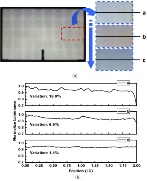
Fig. 3. (a) Photographed image on the left is the intensity distribution of backlight by virtue of super-Gaussian LSF without compensation of the second LC panel. Nevertheless, the visible grid lines, shown in the photos on the right, can be gradually reduced from top to bottom (a to c) by modifying the parameters of the super-Gaussian LSF and the corresponding compensation of the second LC panel. (b) The corresponding cross-section profiles of central lines a through c. In the case of c, the adjusted parameters can achieve variation of 1.4%, which is less than the empirical value of 2% in the current DLCP system.
and are the mean values of the two LSFs. The correla-tion coefficient provides an important measure for the LGU de-sign. After finding the qualified via the testing platform, we can iteratively adjust the optical parameters of the LGU to ensure that the correlation coefficient is at least higher than 95%, which ensures the indistinguishable difference between the two LSFs.
III. EXPERIMENTS
A. Testing Platform
A dual-liquid-crystal-panel (DLCP) platform was con-structed to attain the qualified as the design target, and then to verify the system performance with the resultant . The pseudo-HDR display was composed of two com-mercially available LCDs, ASUS VW193D [14], as depicted in Fig. 6. With a diffusing sheet on top, the rear LCD was served as a pseudo backlight module with 8 by 5 local partition. Meanwhile, the front LC panel with resolution 1440 by 900 pixels, after removing the backlight module, was functioned as the substantial LC panel. The resultant uniformity, based on the
Fig. 4. A cross-section family of a super-Gaussian distribution with different parameters, A and p, based on the (1). In addition, all the super-Gaussian LSFs have identical energy in this figure.
ANSI-thirteen-points specification, of the DLCP system was 68% due to placement of the diffusing sheet. The maximum
CHENG et al.: DESIGN AND EVALUATION OF LSF FOR AREA-ADAPTIVE LCD SYSTEM 69
Fig. 5. Schematic diagram of the LGU consists of a side-emitting LED in cen-tral, a quadratic LG (QLG) at bottom, and a concentric prism sheet (CPS) on the top.
Fig. 6. Schematic diagram of the DLCP system which is composed of an LCD, a diffuser and an LC panel.
and minimum luminances of the DLCP system were 10.2 and 0.01 cd/m , respectively, which was able to provide a sufficient contrast range over 1 000:1 for the testing.
B. Testing Items
The overall backlight uniformity was first investigated, and so was the similarity between the and the . Then, luminance uniformity, contrast ratio, and processing speed were the three key parameters for evaluation and comparison between the resultant super-Gaussian LSF, , and the commonly-applied Gaussian LSF. Different LSFs were offered by the rear LCD in the DLCP system. The kernel was of size 220-by-220 pixels, including the tails out of the ideal image area of size 180 by 180 pixels. Meanwhile, the Gaussian LSF kernel was of size 540 by 540 pixels where the standard deviation, , was 90 pixels, which was half the size of the ideal LSF width. In addition to kernel size, the summation of luminance value of each kernel was set equal for energy conservation.
IV. RESULTS ANDDISCUSSION
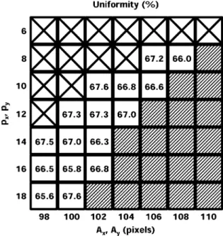
In addition to invisibility of grid lines, the set of qualified could imply high system uniformity, calculated by ANSI-thirteen-points specification, as well. Certain range of equation parameters ( and ) were summarized to explain the situation, as shown in Fig. 7. The cross-sign region denoted untested parameters where the superimposed luminous intensity at the division boundary was less than the central value and thus insufficient for backlighting requirement.
Fig. 7. The uniformities of super-Gaussian LSFs with different parameters. The regions with cross-sign, slash, and blank field denote the untested, the un-qualified, and the passed parameters, respectively. The average uniformity of the passed regions is 66.8%.
The slash regions indicated where the grid lines, incapable of being compensated by the front LC panel, were visible to degrade the panel uniformity. Subsequently, blank regions, representing the acceptable values, companied with high uni-formity approaching to the value, 68%, of the DLCP system with full-on backlighting. The uniformity 68% of the DLCP system arose from precision loss during manual construction. Furthermore, the uniformities, shown on the blank regions, were indistinguishable visually, so we could arbitrarily choose one of the qualified for design convenience.
The proposed optomechanical layout, the LGU, was verified in terms of the correlation coefficient (CC) between the resultant
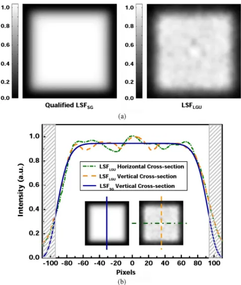
and an example qualified , with
pixels, and . The intensity pro-files of the two LSFs were shown in Fig. 8(a). The ripples at the flat-top region of the , as shown in Fig. 8(b), could be confined within % average luminance . In this case, the CC was 96.67%. The redundant light, trailing over the slash re-gions in Fig. 8(b) and attributed to the inadequate design of the QLG edge, was the main cause to reduce the similarity between the two LSFs. Except for the slash area, the CC could achieve 98.91% which was more capable of representing the . Therefore, we concluded that the proposed optical setup could create a nearly square light distribution for area-adaptive back-light.
According to the ANSI-thirteen-points specification, the uni-formity was 40.8% when the whole screen was illuminated by the conventional Gaussian LSF ( pixels, and .). The backlight uniformity resulted from the with the optimal parameters pixels and was 66.8%, whereas the one of the corre-sponding was 63.3%. All the three cases were mea-sured after the compensation of the front LC panel. Compared
Fig. 8. (a) A qualified, formulated light spread function,LSF , with Lav = 0:95; A = 102, and p = 10, in comparison with the corresponding emitting profile,LSF , produced by the optimized light guide unit. (b) The comparison of corresponding cross-section. The redundant light in slash region arisen from the inadequate design of the QLG edge is the main defect to reduce the similarity.
Fig. 9. Test images for evaluating the contrast ratio at: (a) testing points a and b; (b) testing points c and d; and (c) testing points e and f.
with the uniformity, 68%, of the full-on backlighting DLCP system, the proposed super-Gaussian luminous pattern and cor-responding optomechanical setup were able to render an ade-quate backlighting solution for HDR-LCD without the expense of uniformity and optical efficiency.
To further examine the performance in contrast ratio (CR), three testing images were displayed and measured under the il-lumination by the aforementioned Gaussian LSF and , respectively. The measurement was made at the two-pair test points (TPs) in each image, as shown in Fig. 9, and the CR was tabulated in Table I. The improvement factor of CR by using ranged between 1.95 and 4.15. In comparison with the Gaussian LSF, the had the superiority to maintain the
luminance of the white areas and to suppress the luminance of the dark area adjacent to the white ones. The results asserted that the proposed LSF was in general useful to achieve high CR for images with sharp luminance variation.
Finally, the processing time was tested using the same compu-tation procedure and program. The difference mainly occurred at the size of the LSF kernel. In current situation, speed for the convolution computation with was a factor of 4.82 faster than with current Gaussian LSF. In fact, the super-Gaussian LSF was potential to improve the computation efficiency since the extent of overlapping between the adjacent super-Gaussian LSFs was much less than that of the general Gaussian LSF, so was the computation consumption.
CHENG et al.: DESIGN AND EVALUATION OF LSF FOR AREA-ADAPTIVE LCD SYSTEM 71
TABLE I
COMPARISONS OF THECONTRASTBETWEENGAUSSIAN ANDSUPER-GAUSSIAN
LSFS IN THESIXTESTPOINTS, WHERE“G” DENOTED THEGAUSSIANLSF
AND“S-G”THEOTHER
V. CONCLUSION
The applicability of the proposed methodology, based on two-dimensional super-Gaussian LSFs, was demonstrated by means of the DLCP system. In the experimental setup, luminance uniformity, contrast ratio and processing speed of the proposed HDR scheme could be improved by factors of 1.55, 1.95–4.15, and 4.82, respectively. The enhancement on contrast ratio showed that such LSF was particularly effective to improve image contents subject to the abrupt luminance variance in an HDR system. In addition, the methodology was capable of scaling the LGU to meet any panel dimension with moderate design parameters. Finally, the proposed optome-chanical layout was applicable to both the HDR LCD and the conventional full-on backlighting LCD as well.
Two further considerations will be helpful to improve the methodology and to extend the applications. Firstly, the vis-ibility of backlight grid pattern is being evaluated directly by visual discrimination. Although the result is accurate, this method is time-consuming. Some vision-based color appear-ance models, like CIECAM02 or iCAM, may be useful to promote the efficiency of the design flow with acceptable assessment. The other concern will be the thickness of the complete backlight module. Thinner LC monitor or LCD TV is highly desirable. However, limited thickness of the backlight module will affect the tolerance of LGU design, and, conse-quently, the yield. Therefore, more trade-offs should be made on LED emitting profile, optomechanical tolerance, etc.
ACKNOWLEDGMENT
The authors would like to thank P.-I Lu of National Chiao Tung University, Hsinchu, Taiwan, for his technical assistance.
REFERENCES
[1] H. Seetzen, W. Heidrich, W. Stuerzlinger, G. Ward, L. Whitehead, M. Trentacoste, A. Ghosh, and A. Vorozcovs, “High dynamic range dis-play system,” Proc. ACM SIGGRAPH, vol. 23, no. 3, pp. 760–768, 2004.
[2] F. C. Lin, C. Y. Liao, L. Y. Liao, Y. P. Huang, H. P. D. Shieh, P. J. Tsai, T. M. Wang, and Y. J. Hsieh, “Inverse of mapping function (IMF) method for image quality enhancement of high dynamic range LCD TVs,” in SID Symp. Dig. Tech. Papers, 2007, vol. 38, pp. 1343–1346. [3] T. Shirai, S. Shimizukawa, T. Shiga, S. Mikoshiba, and K. Käläntär,
“RGB-LED backlights for LCD-TVs with 0D, 1D, and 2D adap-tive dimming,” in SID Symp. Dig. Tech. Papers, 2006, vol. 37, pp. 1520–1523.
[4] H. J. Peng, W. Zhang, C. K. Hung, C. J. Tsai, K. W. Ng, S. I. Chen, D. Huang, Y. L. Chueng, and Y. Liu, “High contrast LCD TV using active dynamic LED backlight,” in SID Symp. Dig. Tech. Papers, 2007, vol. 38, pp. 1336–1338.
[5] Y. H. Lu, Y. K. Cheng, and C. H. Tien, “A localized pattern approach for high-dynamic-range display,” in SID Symp. Dig. Tech. Papers, 2007, vol. 38, pp. 449–452.
[6] S. Swinkels, R. Muijs, E. Langendijk, and F. Vossen, “Effect of back-light segmentation on perceived image quality for HDR display,” in
Proc. IDW’06, 2006, pp. 1451–1454.
[7] J. A. Hoffnagle and C. M. Jefferson, “Beam shaping with a plano-as-pheric lens pair,” Opt. Eng., vol. 42, no. 11, pp. 3090–3099, 2003. [8] A. Parent, M. Morin, and P. Lavigne, “Propagation of super-Gaussian
field distributions,” Opt. Quantum Electron., vol. 24, pp. S1071–S1079, 1992.
[9] Philips Lumileds, Luxeon III Emitter Technical Datasheet (03/31/ 2006) [Online]. Available: http://www.lumileds.com/pdfs/DS45.PDF (Retrieved Mar. 17, 2008)
[10] K. Käläntär, “Functional light-guide plate for backlight unit,” in SID
Symp. Dig. Tech. Papers, 1999, vol. 30, pp. 764–767.
[11] C. H. Tien, Y. H. Lu, and Y. J. Yao, “Tandem light-guides with micro line-prism arrays for field-sequential-color scanning backlight module,” J. Display Technol., to be published.
[12] Vikuiti™ Business Partner Website, Vikuiti™ BEF III. [Online]. Avail-able: http://multimedia.3m.com/mws/mediawebserver?66666UuZjcF-SLXTtlx&2MXfcEVuQEcuZgVs6EVs6E666666 (Retrieved Mar. 17, 2008)
[13] K. Erwin, Introductory Mathematical Statistics. New York: Wiley, 1970.
[14] ASUSTek Computer Inc., LCD Monitors, 19 Widescreen VW193D [Online]. Available: http://usa.asus.com/products. aspx?l1=10&12=87&13=545&14=0&model=1688&modelmenu=2 (Retrieved Nov. 23, 2008)
Yu-Kuo Cheng received the B.S. degree in electrophysics from National Chiao Tung University, Hsinchu, Taiwan, in 1997. Since 2003, he has been working toward the Ph.D. degree in Institute of Electro-Optical Engineering at National Chiao Tung University.
In 2001 and 2002, he was an electronic engineer responsible for projector system design in BenQ Corporation., Taiwan. In 2006, he was granted for a year as a visiting researcher in Munsell Color Science Laboratory, Rochester, NY. His current researches are color engineering, and color vision-based system design of field sequential color (FSC) LCDs and high dynamic range (HDR) LCDs.
Yen-Hsing Lu received the B.S. degree in communication engineering from National Chiao Tung University, Hsinchu, Taiwan, in 2004, and is currently working toward the Ph.D. degree in the Institute of Electro-Optical Engineering, National Chiao Tung University.
His current research interests are the optical design for high-dynamic-range display and the color appearance model for LCD.
Chung-Hao Tien received the B.S. degree in communication engineering and the Ph.D. degree in electro-optical engineering from National Chiao Tung Uni-versity, Hsinchu, Taiwan, in 1997 and 2003, respectively.
He joined National Chiao Tung University as an assistant professor at Depart-ment of Photonics and Display Institute since 2004, after as a post-doctoral re-search staff at Carnegie Mellon University, Pittsburgh, PA. His current rere-search interests are in optical data storage and non-imaging optics.
Han-Ping D. Shieh (S’79–M’86–SM’91–F’08) received the B.S. degree from National Taiwan University in 1975 and Ph.D. in electrical and computer engi-neering from Carnegie Mellon University, Pittsburgh, PA, in 1987.
He joined National Chiao Tung University (NCTU), Hsinchu, Taiwan, as a professor at Institute of Opto-Electronic Engineering and Microelectronics and Information Research Center (MIRC) in 1992 after as a Research Staff Member at IBM TJ Watson Research Center, Yorktown Heights, NY, since 1988. He was an Associate Director, at MIRC, NCTU. He founded and served as the Director, Display Institute at NCTU in 2003, the first such kind of graduate academic institute in the world dedicated for display education and research. He is also holding a joint-appointment as a Research Fellow at Center for Applied Sciences and Engineering, Academia Sinica since 1999. He was appointed as a co-PI of “Display Science and Technology Large-Scale Project” in 2004, a national project to drive Taiwan display into new era. He is currently the Dean, College of Electrical and Computer Engineering, NCTU and AU Optronics Chair Pro-fessor.
Dr. Shieh is a Fellow of Optical Society of America (OSA) and of Society for Information Display (SID).