computer
ELSEVIER Computer Communications 21 (1998) 445-459
Design and analysis of delay control for CBR services in ATM networks
Y.C. Chen*, C.T. Chan, S.C. HuDepartmenr of Computer Science and Information Engineering, National Chiuo Tung University, tfsinchu, Taiwan 30050, ROC Received 2 September 1997; revised 9 December 1997
Abstract
Asynchronous transfer mode (ATM) networks are designed to provide end-to-end transport of user data via virtual connections with specified quality of services (QOS), which is expected to be satisfied through effective traffic control mechanisms. This paper presents an adaptive delay-jitter control (ADJC) method that guarantees the delay bounds of constant bit rate (CBR) services in ATM networks. Our proposed method is based on a node-by-node time-frame scheme. Through both mathematical derivation and simulation, we have demon- strated that ADJC features a significant improvement over existing approaches in jitter delay, which can be reduced to one time-frame
from end-to-end for CBR traffic. Simulation results have shown that CBR services receive satisfactory delay performance using our
approach. 0 1998 Elsevier Science B.V.
Keywords: ATM; CBR services; Adaptive delay-jitter control
1. Introduction
The asynchronous transfer mode (ATM) is selected as the
basis of B-ISDN due to its flexibility and efficiency for
accommodating a wide range of services. The high band-
width offered by ATM networks makes real-time appli-
cations, such as audio/video transport, feasible. To support
these applications, ATM networks are designed to provide
end-to-end transport of user data with specified quality of
services (QOS), which is expected to be satisfied through
effective traffic control. Usually, in high-speed networks
such as ATM, the propagation delay between intermediate
nodes is relatively long compared with the packet (cell)
transmission time, thus the reactive control method may
not be effective to accommodate delay-sensitive traffic
(e.g. constant bit rate (CBR) traffic, real-time traffic). On
the other hand, preventive control approaches [l-7] which
try to avoid network congestion in advance are more pro-
mising. The cell scheduling discipline at each intermediate
node determines whether a cell is ready to be transmitted
based on its QOS requirement. There are work-conserving
and non-work-conserving cell scheduling disciplines. In the
former the transmission is never idle as long as there is a cell
waiting to be sent. Several well-known examples are
weighted fair queuing (WFQ) (81, virtual clock [lo],
* Corresponding author. Tel.: 00886 3573 1864; fax: 00886 3572 7842; e-mail: [email protected]
0140-3664/98/$19.00 0 1998 Elsevier Science B.V. All rights reserved
PII SO l40-3664(98)001 19-4
packet-by-packet generalized processor sharing (PGPS)
[9,24] and self-clocked fair queuing (SCFQ) [ 11,12,25].
While in the latter, the transmission may be idle even
when there are cells ready to send; some popular examples are stop-and-go framing (S&G) [ 15-171, hierarchical round
robin (HRR) [18], rate control static priority (RCSP)
[ 11,19,20] and traffic-controller rate-monotonic priority
scheduling (TCRM) [21]. Work-conserving disciplines pro-
vide lower average queuing delay and larger end-to-end
delay jitter than non-work-conserving disciplines. In
work-conserving discipline, traffic needs to be characterized
inside the network on a per connection basis to derive end-
to-end delay bounds and buffer space requirements.
However, the traffic pattern is usually distorted inside the
network due to the cell transmission contention, and it is
difficult to restore the original traffic pattern after the
distortion.
The non-work-conserving disciplines have several advan-
tages for supporting CBR services. These advantages
include : (1) the end-to-end queuing delay can be easily
derived through local delay analysis at each intermediate switch; (2) the required buffer space to prevent cell overflow at each switch can be reduced through traffic regulation inside the network; (3) it features shorter delay jitter perfor-
mance and smaller buffer requirement for playing back at
the end system. However, the non-work-conserving
disciplines suffer lower bandwidth utilization because the
446 Y.C. Chen et al./Computer Communications 21 (1998) 445-459 waiting. This problem can be improved by accounting for
non-delay-sensitive traffic in an integrated-services envir- onment. A well-known non-work-conserving discipline, S&G frame strategy, has a remarkable end-to-end delay bound and delay-jitter bound compared to HRR, but its bandwidth management is inflexible and it is difficult to choose a proper time-frame size to meet various application needs. While RCSP provides a nearly optimum packet delay-jitter control for real-time traffic, however, it needs to pass the delay information (cell eligible time) from node to node and to synchronize the clock time of all intermediate nodes precisely, which is extremely difficult in an ATM wide-area network environment. TCRM provides a bounded end-to-end delay for real-time communications. It provides lower average queuing delay compared with S&G, but its delay-jitter control is worse than that in S&G.
This paper presents a feasible traffic control approach that guarantees both end-to-end delay bound and delay-jitter bound for CBR services in ATM networks. Apparently, we can reconstruct the characteristics of a CBR stream at the end system as long as its delay-jitter bound is guaran- teed. We proposed a cell scheduling method based on time- frame synchronization and non-preemptive priority sorting, and demonstrated through mathematical derivation and system simulation that our cell scheduling method achieves a significant improvement over existed approaches in end- to-end delay jitter, as well as provides an adaptive delay- jitter control with end-to-end delay jitter reduced to one time-frame. The organization of this paper is as follows. Section 2 addresses the traffic control framework. In Section 3 the mathematical analysis of the proposed method is pre- sented. The system simulation and performance evaluation are discussed in Section 4. Section 5 concludes the work.
2. The traffic control framework
Constant bit rate (CBR) services such as CBR audio and video are expected to comprise a significant portion of the traffic on ATM networks. Two important QOS measures for CBR traffic are the end-to-end delay and the delay-jitter, which can be guaranteed with an effective strategy for bandwidth reservation and traffic control. We use a time- frame-based technique that combines both call admission and cell scheduling policies to accomplish the task. The former decides whether to accept or to reject an incoming connection request, so that network loading can be kept below the congestion level, and the delay bounds of those accepted connections can all be satisfied, while the latter
reconstructs the time property of the admitted traffic in each intermediate node, and this is essential to guarantee the queuing delay bound. The source traffic must be shaped through a regulator as smooth traffic pattern in which the cell interarrival time is restricted. Before presenting the proposed traffic control scheme, it is necessary to define the simple-smooth traffic in the ATM network as follows.
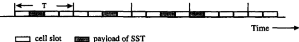
Definition 1. In ATM network, the cell stream of a con- nection is defined as simple-smooth trafJic (SST) with time frame T (in cell slot) if, during each non-trivial period T (i.e.
T > l), there is at most one cell transmission of the same stream. A connection that carries an SST in the network is called an SST connection or an SST stream.
Assume a CBR connection has a guaranteed bandwidth R
with time frame T, which is obtained through negotiation during the connection setup based on the cell interarrival characteristics, where T = [C/R], and C is the link capacity. Fig. 1 shows an SST stream, the traffic of a CBR connection in the network will be regulated as an SST stream through- out the network using our proposed strategy.
Before we proceed to the discussion, it has to define the terminology of eligibility.
Definition 2. A cell of an SST connection with time frame T is said to be eligible in an intermediate node if it is ready to be scheduled, and its preceding cell of the same connection was scheduled no shorter than T ago.
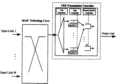
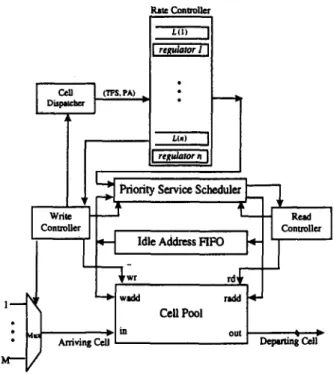
Fig. 2 shows the CBR transmission control configuration of our traffic control architecture. The transmission control- ler (TC) consists of a cell dispatcher (CD), a rate controller (RC) and a priority service scheduler (PSS). The CD dis- tributes a cell to its associated FIFO queue. The RC provides a set of regulators to accommodate each CBR connection. Each regulator shapes the input traffic of the associated connection as SST according to the eligibility rule. The PSS schedules all eligible cells for transmission. Through such traffic regulation, the TC can provide a bounded end- to-end queuing delay for CBR services. Assume that shared memory is used, then each output buffer can be logically partitioned into n separate FIFO queues for holding the incoming cells of the associated CBR connections. In addi- tion, we can assign N priority levels to accommodate the eligible cells from their corresponding CBR service classes. Our proposed strategy is similar to the S&G scheme, Zhang’s RCSP [20] and TCRM [21] in the objective of transmission-control. However, our service discipline pro- vides a significant improvement in the average end-to-end queuing delay compared with the first scheme, and features
Time e 0 cell slot payload of SST
Y.C. Chen et al./Computer Communications 21 (1998) 445-459 447 Input Link 1 . . Input Link M I 1 MM4 Switching Core :
I
IR
I 1K
Fig. 2. Proposed CBR transmission control in an ATM switching node.
a more realistic time-frame based method for delay-jitter
control compared with the latter two. The main difference between the S&G approach and ours is that ADJC avoids
the extra waiting time through node-by-node synchroniza-
tion, which allows arbitrary time-frame sizes that are not
supported in S&G, while the difference between the delay- jitter control in RCSP and ours is the time synchronization
method. ADJC does not need the cell eligibility time infor-
mation from the upstream node; therefore, not only the
implementation becomes feasible, but also the overhead is
greatly reduced, since per cell time-stamping and time
synchronization between different switching nodes are not
realistic under ATM network environment. While the rate-
jitter regulator in RCSP controls delays jitter by partially
reconstructing the traffic pattern, it introduces large delay
and buffer space requirement at a single switch node.
Although the RCSP avoids the dependencies between prior-
itized scheduling and bandwidth allocation, its stringent
admission control conditions for satisfying the delay-
bound requirement restrict the resource utilization. The
main difference between the TCRM approach and ours is
that ADJC is time-frame based which can be realized using
counters, thus it is more feasible as well as provides a better delay-jitter control.
3. Analysis of proposed traffic control method
First, we propose a simple delay-jitter control strategy
(SDJC), then we will enhance SDJC to an adaptive delay- jitter control strategy (ADJC).
3.1. Simple delay-jitter control (SDJC) strategy
The SDJC deals with two issues: the resolution of
transmission contention among multiple SSTS, and the
maintenance of the outgoing cell stream of each connection
as SST. We set three rules for intermediate nodes. (1) In
order to meet the delay requirement among various service
types, the priority ordering of transmission will prefer the
cell with the smallest time-frame. Of course, this priority
ordering can be adjusted flexibly for practical needs. (2) To keep the traffic pattern of a connection as SST throughout the network, only one cell can be granted eligibility within one time-frame interval for each connection. (3) The transmission for CBR service will be idle if there is no eligible cell.
Let N be the time-frame priority level and nj be the
number of connections with time-frame Tj, where T1 < T2
< ... < TN, 0 5 nj and 1 I j 5 N. When a new CBR connection request is received by the network, a CAC proce- dure is executed to decide whether to accept or to reject the call. If there already existed xr= Ink CBR connections in any
node along the end-to-end path, the newly requested CBR
connection with time-frame Ti can be accepted by that node if the following conditions are satisfied. The first condition,
(1)
ensures that the total traffic load will not exceed the link capacity. It implies that the new CBR connection can obtain
the required bandwidth, while the second condition,
P
I Ti
> Ti and x
fcdll, T,ST, _ ,
< Ti- 19
is necessary to guarantee the queuing delay bound of a CBR
448 Y.C. Chen et al./Computer Communications 21 (1998) 445-459
contention among connections with various priority levels,
the maximum number of cell arrivals within time-frame Ti
from those connections with time-frame less or equal to Ti
must be not greater than Ti(Zq,r)nj X ([T,)/(q)]) 5 Ti) to
guarantee the bounded delay. However, it can also provide the bounded delay in the case that the maximum number of
arriving cells within time-frame 7’i from those connections
with time-frame less than or equal to Ti is greater than Ti. This is because there is an idle cell slot during the Ti_ 1 time- interval. For example, assume there already existed three
connections with T, = 2, T2 = 4 and T3 = 8. When a new
request with T4 = 9 arrives, it will be accepted. This will not deteriorate the QOS of the CBR connection because the new connection will use the idle slot within the time-frame T3. In this case, the CAC must determine whether
~~~~11~ c [;:;I $[# $Ym:!n tlmann~;h~,n,oti.d~~
slot cad be used within Ti_1 time duration. Therefore, the new request connection can be accepted as long as the num-
ber of connections with time-frame Ti is no greater than
[(Ti_ I)/TJ (i.e. ni 5 [(Ti_ I)/TiJ)*
A new connection request is accepted if the network has
enough resources to provide the QOS requirements of the
connection without affecting the QOS already established in the network. Hence, when a new connection request satisfies
the above two conditions, the CAC procedure must further
decide whether admitting the new connection causes the
QOS violation of the existing connection or not. The algo-
rithm for the CAC is stated as follows:
Algorithm Call-Admission-Control:
Declaration:
N: the number of time-frame priority levels Ti: the time-frame size of the new request,
which belongs to class i (1 I i 5 N)
nj: the number of connections with time-frame Tj, where TI < T2 < ..’ < TN
Et= ,nk: the number of existing CBR connections
in an intermediate node
R-Flag: the recursive status flag, it is 0 if the
recursive process is terminated, and 0 otherwise
A-Flag: the output status flag, it is 1 if the new
connection is accepted. and 0 otherwise
Initialization: A-Flag = 0; R-Flag = 1; Begin if l/Ti + xt= 1 (nk X l/Tk) I 1 then CAC(i, Ti); endif end
Procedure CAC(i, Ti): Begin if (R-Flag) then if (i = N) then if ~r,~r,5 X ([TN/q]) 5 TN then A-Flag = 1; R-Flag = 0; else
if &sr,_,nj X ([TN- l/TjI) > TN- I and ni 5 [TN/TN _ 1 ] then A-Flag = 1; R-Flag = 0; endif endif else if xqSTnj X (rTi/Ti]) 5 Ti then CAC(i+ 1, Ti+ 1); else if Zr+r,+, 4 X ([Ti _ ,lTl]) < T; _ 1 and Al; 5 [(Ti)l(Ti _ I)]) then
CAC(i+ l,Ti+,); else R-Flag = 0; endif endif endif endif End
Assume an SST cell has a higher transmission priority
than a non-SST cell, we can show that an SST cell with
time-frame Tk can be transmitted within Tk time interval
once it becomes eligible.
Lemma 1. Given an SST connection k with time-frame Tk, let W;’ be the delay time for its jth cell to be transmitted in node i once it becomes eligible, then 1 I W: I Tk.
Proof. Since the TC transmits eligible cells only, thus
according to the traffic regulation, each SST connection
will have at most one cell ready within each associated
time-frame interval. An SST connection with a smaller
time-frame has higher priority than that with a larger
time-frame, cell transmissions of these connections with
a time-frame no greater than Tk will not be affected by
those with a time-frame larger than Tk. According to our
call admission strategy and priority scheduling, the incom-
ing cell with time-frame T, eligible at time t can always be transmitted within [t + 1,t + Tk]. This assertion is also true
for an arbitrarily chosen time-frame. QED.
Given a connection i with time-frame Ti, we use the
counter C,,(i) to track the cell-eligibility. Once a cell of
connection i becomes eligible, C,,(i) is set to T;, which
then counts down to zero in Ti cell-slot time. When a cell arrives, it checks whether C,,(i) is equal to 0 or not. If yes,
Y.C. Chen et al./Computer Communications 21 (1998) 445-459 449
the arriving cell will become eligible immediately, other- wise it has to wait. Through such a mechanism, the TC can regulate each cell stream to be an SST pattern. The algo- rithm for the TC is stated as follows:
Algorithm for CBR transmission controller: Declaration:
n: the total number of connections
C,,(i): the traffic regulation counter of the ith connection (1 5 i I n)
N: the number of priority levels
T(i): the timeframe of ith connection (1 SiSn,T(i)E {T,,T2;**,T,})
L(i): the ith FIFO queue status. It is 0 if the queue is empty, and 1 otherwise
Initialization:
C,,(i) = 0; i = 1 *aen /* for accepted connections with time-frame Tj */ Begin for (i = 1 to n) do if C,,(i) > 0 C,,(i) = C,,(i) - 1; endif
if (L(i) # 0) and (C,,(i) = 0) then
insert the HOL cell of ith FIFO to the PSS for priority transmission service;
C,,(i) = z-(i) endif
endfor End
Assuming that a connection k with time-frame Tk
routes through H hops, let r1 represent the fixed-time overhead including the cell processing time in the Ith switching node and the propagation delay in the outgoing link, where 1 = l...H, and r. be the propagation delay of the source access link. It is obvious that the end-to-end delay of jth cell for connection k is L$ = rk + QD;,
where .Tk = zr_ ari is the total propagation delay between two end systems plus the total processing time in the intermediate nodes; Q$ = XI”= 1 (I$ where Qi is the total queuing delay of the jth cell in the ith switching node. a includes 4, the queuing delay (excluding the fixed processing time) of jth cell waiting for eligibility after it finishes the necessary processing in the ith node, and W{, the delay time for the jth cell to be transmitted once it becomes eligible at node i. Then we have the follow- ing lemma.
Lemma 2. For any SST connection k with time-frame Tt,
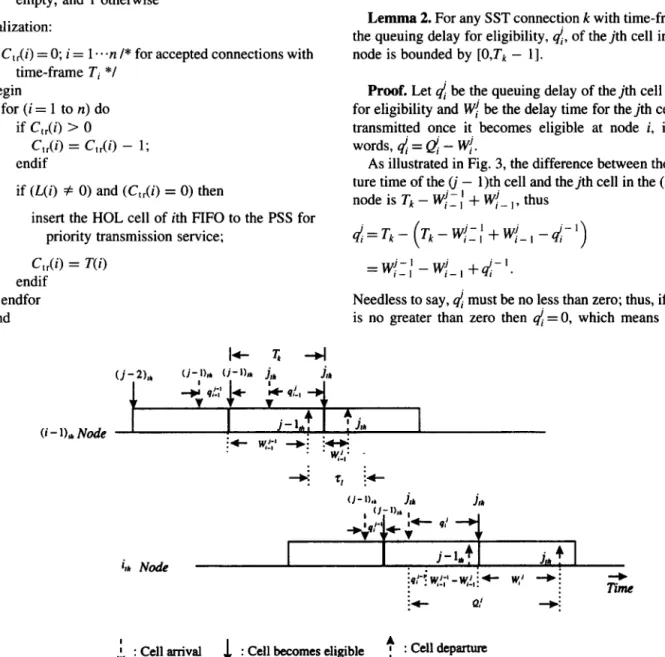
the queuing delay for eligibility, 4, of the jth cell in the ith node is bounded by [O,Tk - 11.
Proof. Let 4 be the queuing delay of the jth cell waiting for eligibility and Wi be the delay time for the jth cell to be transmitted once it becomes eligible at node i, in other words, 4 = & - W/.
As illustrated in Fig. 3, the difference between the depar- ture time of the (j - 1)th cell and thejth cell in the (i - 1)th nodeisTk-IV-’ r_, + W;_,, thus
d=T,-(T,-Wj_:+Wlj_,-d-‘)
= w{J - w;_i +d-‘. (3)
Needless to say, 4 must be no less than zero; thus, if Eq. (3) is no greater than zero then di = 0, which means that the
U - 1h Node
(j-Ile (i-h +h . Ilk
I*- 9!., * irk Node j-1,. “1 : - i”’ lyy - W,!, ; 4- w,’ -+ : TZ + Q! *:
1 : Cellarrival 1 : Cell becomes eligible + , : cell departure
450 Y.C. Chen et al./Computer Communications 21 (1998) 445-459
arriving cell is eligible immediately; otherwise
4 = d- ’ + W{_: - W:_ , , hence the following equation
QL$ = xy=, a and @ is the total delay of the jth cell in the ith node.
w;:; -w{_, +q/-’ >o
, where qf =O, i= l...H, j= 1,2, .*a. (4)
otherwise
must hold for any cell j of connection k in the ith node. It is evident that 4 should have a positive value from Eq. (3). To derive the upper bound of d, we expand Eq. (4) as follows
4 =qj-‘+W/~; -w;_,
- Wi-t+Wj-1-W’
1-l t-l i-l’
(3 Since C,,(i) is preset to 0, when the first cell of a connection arrives, it becomes eligible immediately, i.e.,q! = 0, where i = 1 . ..H. Therefore, the maximum value of 4 can be derived as follows:
where i 2 2. (6)
Since the traffic from the source is in SST pattern, thus 4 will have the same property as 4 for i 2 2. From Lemma 1, it is clear that d is bounded by [O,Tk - 11. QED.
Theorems regarding the traffic property under the SDJC strategy are given as follows:
Theorem 1. For any SST connection k with time-frame T,, the maximum delay, a of the jth cell in the ith node is bounded by [1,2Tk - 11.
Proof. Since & consists of two parts, the queuing delay waiting for eligibility and the delay to complete the trans-
mission, from Lemma 1 and Lemma 2, the following
inequality
O<ej=W;+q+2Tk-1 (7)
must hold for any cell of connection k. Clearly, the queuing delay @ of thejth cell in the ith node is bounded by [ 1 ,2Tk - 11. This completes the proof. QED.
If the jth cell becomes eligible immediately after its arri- val at the ith node (i.e. d = 0), the total queuing delay of the jth cell will be no greater than Tk. Otherwise (i.e. 4 # 0), the total queuing delay of the jth cell may be larger than Tk in the ith node. It is obvious that the end-to-end delay of thejth
cell of a given connection k is 0; = .Tk + QDf, where
Theorem 2. For any SST connection k with time-frame Tk, which routes through H hops, the end-to-end delay 0; = 7k + QDj” is bounded by [.7k + H, .Tk + HTk + Tk - I],
where QD;Zf!=, a.
Proof. The delay time, QD~~~f, & of the jth cell can be substituted by
QD;= &q{+W;)=q;+W;+q;+W;+...+q:, i=l
If the CBR source traffic is regulated as a constant traffic pattern (i.e. fixed interarrival), the values of q! and 4 ,will be equal to 0. From Lemma 1 and Lemma 2, W: and 4 are
bounded by [l,Tk] and [O,Tk - 11, respectively, thus Eq. (8)
becomes H-l QD;=d;+ 1 Wi’ +W+HTk ( 1 (9) i= 1
It should be pointed out that if a source traffic is not regu- lated as a constant traffic pattern, the time intervals between
any two data cells in consecutive time-frames may be not
identical (i.e. 0 5 di 5 Tk - l), thus
HsQD;‘(Tk-l)+HTk. (10)
As a sequel, the maximum end-to-end delay of the jth cell
for connection k is bounded by
#+H&+QD;&+(Tk-l)+HTk. This completes the proof. QED.
(11)
From Theorem 2, we can find out that the delay-jitter of SDJC is (H + l)(Tk - 1). In order to achieve a better delay-
jitter performance, we improve SDJC to the adaptive delay-
jitter control described as follows.
3.2. Adaptive delay-jitter control (ADJC) strategy
As stated in the previous subsection, once an incoming
SST cell with time-frame Ti becomes eligible at time t, it
can be transmitted within the eligible time interval [t + 1,t + Ti]. To achieve our adaptive delay-jitter control, we intro- duce a specific time interval T,(l 5 T, I Ti) which is used
Y.C. Chen et al./Computer Communications 21 (1998) 445-459 451
Deparhmfmmingintbc
upmwm node via link I’
Arrival fiatning in the yr,-*:r,+
: I-r--
_____
curtent node via link I’ I f I I
I +Gi4-
Dcpamuefmminginlbc I
cuttent ncdc via link I
Depattutc framing in the upsucam node via link I’
Attival fmming in the
7 q + r, + I-” --- CuffeOt node via link I’ : I *l I I
I ;*-rr+
Deplrturr mng in the ’
current no& via link 1
I
I f
Cdlbecomes eligible (b) $ >T,
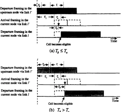
Fig. 4. Illustration of the adaptive delay-jitter control.
to determine when an incoming cell should become eligible in the current node. Assume that the current node i has an
outgoing link 1, and an incoming link I’ connecting to the
upstream node i - 1. If an incoming cell j is served at time t’ + T, (i.e. TP = W{_ ,) in the upstream node after it became eligible at time t’, where Tp I T,, then it will be delayed for a duration T, - Tg, before it becomes eligible in the current node, as shown in Fig. 4(a). Otherwise, if To > T, due to the
transmission contention in the upstream node, the incoming
cell will become eligible immediately, as illustrated in
Fig. 4(b).
The question is, how can an intermediate node know
the time interval T, which is used to determine the delay
(i.e. T, - To) for an incoming cell to be eligible? To resolve
this problem, we investigated the behavior of any two con-
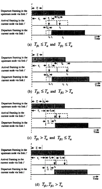
secutive SST cells under ADJC. Assume that two consecu- tive SST cells A and B arriving via link 1’ and heading for link 1 were served in the upstream node at times t’ + Tpl and t’ + Ti + To2 after they became eligible at times t’ and t’ + Ti respectively. In the first case, TB,, To2 5 T,, the incom- ing cell A with time-frame Ti will be delayed a time duration T, - To, (i.e. tl - to) before it becomes eligible at time lI in the current node, then the cell A can be transmitted within the time interval [t, + l,t, + Ti] and the following cell B will become eligible as soon as this time interval is over.
The waiting time for eligibility of cell B in the current
node is T, - To2 (i.e. t3 - tz), as shown in Fig. 5(a). The second case is T,, 5 T, and Tb2 > T,. Owing to the trans-
mission contention in the upstream node, cell B’s arrival
time, t4, is later than the ending time of cell A’s eligible
region (i.e. t3 or (tr + Ti)), thus it becomes eligible
immediately, as shown in Fig. 5(b). Similarly, the other
two cases are To, > T,, To2 5 T, and ToI, Tp > T, as
illustrated in Fig. 5(c) and Fig. 5(d), respectively. It can
be found that no matter how early or how late cell B arrives, it will not be eligible until the eligible time interval of cell A is over.
Since an arriving cell immediately becomes eligible only
when the eligible time interval of the preceding cell is over,
the feasibility consideration of ADJC is regarding the com-
plexity imposed on each intermediate node to set the time
framing of the first data cell for each SST connection. To
alleviate the extra loading of intermediate nodes, a leading RM cell can be used to indicate the start of an SST cell stream, and a reserved field can be used to carry the queuing delay information T, of the RM cell itself in the upstream node. Before a CBR traffic source starts the cell trans- mission, it needs to send an RM cell first. When the leading RM cell is received by an intermediate node, the cell trans-
mission delay information Tp of an SST stream in each
intermediate node can be carried to the next downstream
node. Since the parameter T, can be set during the connec- tion setup, the queuing delay for an RM cell waiting for eligibility after it arrives at the current node is equal to [T, - Ta]*. Then, the following data cells only need to obey a simple rule to achieve the adaptive delay-jitter con- trol, that is, an arriving cell immediately becomes eligible as
soon as the eligible time interval of the preceding cell is
over. As a consequence, our service scheduling method
removes the extra waiting time through node synchroniza- tion, and it supports an arbitrary time frame. In the rest of
452 Y.C. Chen et al./Computer Communications 21 (1998) 445-459
Depamue framing in the
;c
r+i
upmaol node via link I’ Arrival fmning in the CuTcot node via link I’
Depamm framing in tbe ’
cunult no& via link I
Deparhm framing in the +s- & upstream no& via link 1’
Arrival framing in the current no& via link I’
I 14
Depamm framing in the cuffcot node via link I
I 4 ‘I
I Tim?
(b) Ts, I T, and Tsz > T,
Depamue framing in the
upstream ode via liok I’ Arrival framiog in the cumot ode via link I’ Departwe hniog in the cunu3toodcvialiokI
(c) Ts, > T, and Ta2 < T,
t
Depamuehmiogiothe + & upstream node via Iink 1’
Arrival framing in the current ncde via link I’ Depammffamingiofbc
cumotoodevialiokf
I 1
Fig. 5. Illustration of the relationship between two consecutive cells under ADJC.
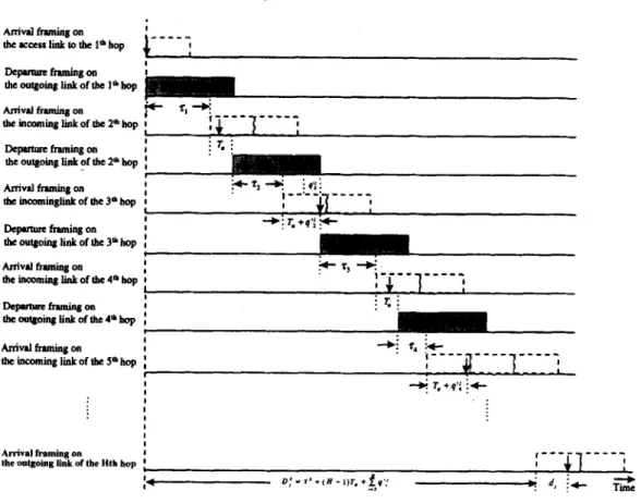
adaptive delay-jitter control. Assuming an SST connection k As shown in Fig. 6, the total end-to-end delay of the jth cell with time frame Tk routes through H hops, we can define the
time interval q’{ as follows:
for a given connection k with fixed cell interarrival time is represented as follows:
qlj =
{
0 if Ts 5 T,
To-T, otherwise ’ where i= l...H, j= 1,2, .--, (12)
+g+QD;=$+ f(Ta+qr;)+d,=$+(H-1)T,
i=2
where Ts is the time interval of jth cell to finish the trans- mission once it becomes eligible at the (i - 1)th node. Clearly, q’{ is bounded by
Osq’{‘Tk-T, (13)
H
+ &(q':)+d, 5 #+HTk, (14)
where dj is the time interval for the jth cell to finish transmission after it becomes eligible at the Hth node (i.e. dj = I+$,, 1 5 dj 5 Tk). Since q’{ is bounded by
Y.C. Chen et al./Computer Communications 21 (1998) 445-459 453 DepMutcftamingotl : theoutgoittglinkoftheI’kop Arrival framing on 0 tkinmmingliikoftke2”‘kop I I Dcpuwrc framiig 0” the outgoing link of the 2’ hop
i--e- e---e
I I I
Anivd framing on : iy-71-+ : *a; i the Lneominglink of the 3’ hop a )_A_’ -____ I
‘ I
Depucurrfnminson :
+T +: r l +q’; F the outgoing link of tke 3’ hop :
Arrival fmmiig 0” I theincominglinkofthe4~hop : -+i r, +qy ic : . : : Arrival framing on ,---- the outgoing link of the Hth hop :
m--m_
I 8 I
:* D:-rwm.+&:’ + d, ;+ Gt
Fig. 6. Cell delays incurred during the transmission process in ATh4 networks.
[O,Tk - T,], then the end-to-end delay is bounded by
rk+(H-l)7-,+l +%.k+HTk. (15)
It should also be pointed out that if a source traffic is not regulated as a fixed interarrival traffic pattern (i.e. 0 5 4 5 Tk - l), then
(lo) Clearly, the end-to-end delay of thejth cell for connection k
is bounded by
&(T,-l)+(&l)T,+l 5D+rki-(T,-l)+HTk.
(17) From the above discussion, it is apparent that we can adap- tively control the delay-jitter. For example, let us set the time interval T, to Tk , then the end-to-end delay of a given cell of the connection k is bounded by
[rk+HTk, #+((H+l)Tk-l].IfwesetT,tol,theresults
will be the same as that in the SDJC strategy. Obviously, in ADJC the end-to-end delay-jitter can be adaptively con- trolled. In addition, the end-to-end delay (excluding total propagation delay) of a connection is reduced from 2HTk
in S&G to (H + l)Tk in our ADJC strategy. Compared to S&G, there is a significant improvement in the end-to-end queuing delay for an arbitrary time frame size. More impor- tantly, we can use the delay parameter T, to adaptively reduce the delay-jitter down to Tk - 1 and to precisely meet the services’ requirements.
For further analysis of the smoothness property, we now investigate the relationship between the incoming cells. Given a source traffic with time frame size Ti, owing to the transmission contention among different connections, the cell transmission may be delayed, which may cause the time interval between two consecutive cells of the same connection smaller than T;. Moreover, it is possible that two consecutive .SST cells are interclustered back to back. According to the TC algorithm, it maintains the traffic smoothness for each connection based on per-VC queuing. Cells of an SST connection with time frame Ti always keep the SST pattern throughout the network. Given Num SST connections in a switching node, for the Ith connection (1 5 1 I Mm), it is possible that the FIFO occupancy, L(I), will be greater than 1 under the proposed service discipline. For an SST cell stream, the kth incoming cell should com- plete the transmission before the (k + 2)th cell arrives, thus two-cell buffer space is sufficient for each connection to prevent FIFO buffer from overflow; in other words, using our proposed method, SST streams only need a total buffer space of 2 X Num cells in the output ports to avoid buffer overflow.
The proposed strategy can support a bounded queuing delay and prevent network congestion for CBR traffic mainly because the strict transmission control always keeps the traffic pattern as SST throughout the ATM network. Since non-delay-sensitive traffic can tolerate longer delay comparing with delay-sensitive traffic, the utilization problem can be compensated by accounting for
454 Y.C. Chen et al./Computer Communications 21 (1998) 445-459 non-delay-sensitive traffic, such as ABR and UBR services,
in the integrated service environment. If there is no eligible CBR cell to transmit, the idle time can be used to service non-delay-sensitive traffic or other types of traffic. Such integrated service policies can offer higher bandwidth utili- zation. In the remainder of this section, we examine the realization of a possible approach for our proposed traffic control.
3.3. Realization of the proposed trafJic control method
We have shown that our proposed CBR transmission con- trol configuration has three components, a cell dispatcher, a rate controller and a priority service scheduler. At first, arriving cells are classified and written into the cell pool. Prior to this process, the associated traffic property (i.e. time frame size, TFS) is extracted by the CD and stored with its physical address (PA) into the associated queue at the RC. The RC consists of a set of regulators, each corresponding to a connection. A regulator has two functions: setting the eligibility of those HOL cells for all non-empty queues and holding a cell until it becomes eligible. The regulator can be realized by a synchronous countdown counter with parallel load, as shown in Fig. 7. This realization approach is inflexible since the number of regulators is directly propor- tional to the number of active CBR connections. We can conceptually decompose the RC into a set of regulators, and as each is associated with a connection, we have no need of multiple physical regulators in the implementation; a com- mon mechanism employees a modified version of the calen- dar queue, which is shared by all logical regulators [19,22,21]. The PSS consists of several modules in which the TFS and PA are stored. Once the HOL cell of a queue becomes eligible, the pair (TFS, PA) of the cell will be stored into the PSS. As stated in the previous subsection, to meet the delay requirements for each service class, the transmission priority is set to prefer the smallest TFS. When cells are served by the PSS, the server compares the TFSs of those eligible cells and selects the smallest TFS for trans- mission since the cell with the smallest TFS value is the most urgent. The major complexity of the PSS is to select the smallest time-frame-size among all eligible cells. Using
Binary Count-Down Counter - t Clock
Fig. 7. A realization of the regulator.
I-
r‘ig. 8. Implementation architecture of the proposed traffic controller.
hardware, implementation is preferable for high speed ATM, e.g. 2.78 ~LS cell transmission time at 155.52 Mbps. We can use the available VLSI Sequencer chips [ 13,14,23] to implement the PSS module. Through this hardware realization, the proposed strategies are able to accommodate the CBR cell streams. The implementation architecture of the proposed traffic controller is illustrated in Fig. 8.
4. System simulation and performance evaluation
4.1. System simulation model
For CBR services, a traffic source can be characterized by simple parameters. In our simulation, a simple ATM subnet consists of four switching nodes and nine end-systems, which function as input sources, as shown in Fig. 9. Let these nine connections be established as follows. Sources
A, B, and C connect to switch 1 and then through switch 2 to
switch 4. Sources D and E connect to switch 2 and through the subnet to switch 4. Sources F and G connect to switch 3 and through the subnet to switch 4. Sources H and I route through node 4 to their destinations. All sources pass through the same output link of node 4 which has the heaviest load. There are frames T = 4, 4, 8, 16, 32, 64, 128, 128, 128 (cell slot time) for sources A, B, C, D, E, F,
G, H and I respectively. The switch output port buffer is
organized as parallel FIFOs which share the output link’s bandwidth via a priority scheduling. The major performance measure was the queuing delay. The transmission service of each output link can be modeled as a single server with multiple queues. We assume that every link has a transmis- sion rate of 155.52 Mbps. For the sake of simplicity in
Y.C. Chen ef al./Compurer Communications 21 (1998) 445-459
C E G I
Fig. 9. System model for queuing delay analysis.
455
solmxs l-14 Soureer IS-28 sourus 29-42 Sources 43-56
,
IO DL?sithoos to D88dnuions to Jhiaatioas
1-14 IS-28 29-42
Fig. 10. System model for delay-jitter analysis.
simulating the S&G scheme, we assume that the mismatch phase, 0, of both the arrival frame and the departure frame is Ti/2 in a switching node.
The other model consists of four nodes and 57 sources as shown in Fig. 10. Let these 57 sources be established as follows. Source 0 connects to node 1 and then through node 2 to node 4. Sources i (i # 0) connect to the ([i/l4])th node and then through the ([i/141+ 1)th node to its destination. These nodes were connected through links with 155.52 Mbps capacity. Each source has a time frame
measure considered here is the end-to-end queuing delay of source 0 in the worst case, because source 0 has the lowest priority in service contention.
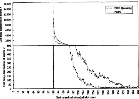
As discussed earlier, the average queuing delay under work-conserving disciplines is smaller than that under non-working disciplines. However, the delay distribution of work-conserving disciplines, such as PGPS and FIFO, has much wider range, as shown in Fig. 11. In the PGPS strategy, source A is allocated with a larger guaranteed bandwidth (i.e. l/TA = l/2) so that its cells have greater Tj = 15 cell slot time, i = 0,l; . .,56. The major performance opportunity for transmission. As
1
16500 < % 14500 12500 ‘;f LOS00 j 85&l C 6SOO g 4500 g 2500 500 * 4scI i! am = 350 .g 300 gi 2 1sa 8 loo 3% 0a result, the number of
Traffic intensity =0.886, q = 2 ..,,..,I 4 8 8 8 8 8 8 8 and the on/off period is 60/40 cell slot time. Fig. 11. End-to-end cell delay distribution of source A by using FIFO queuing and PGPS strategies.
456
90
Y.C. Chen et al./Computer Communications 21 (1998) 445-459
80 70
Fig. 12. Average delay of VCs with different frame sizes by SDJC at switch node 4.
cells to be sent immediately after cells arrive at a switching Consequently, the SDJC strategy provides priority services node is larger than that in FIFO queuing. as well as a bounded delay.
4.2. Simulation results
In the followmg simulation results, the end-to-end delay excludes the fixed propagation delay.
4.2.1. Comparison of end-to-end delay and delay-jitter of SDJC strategy and S&G
Average delay versus traftic intensity. The traffic intensi- ties vary from 0.1 to 0.95 at switch node 4. From the simu- lation results shown in Fig. 12, the average delay time of different time-frame sizes increases as the traffic intensity increases. We also found that the maximum cell delay, Qi, for a given connection never exceeds its upper bound (i.e. 1 5 Qk 5 2Tk - 1) even at a high traffic intensity (0.95).
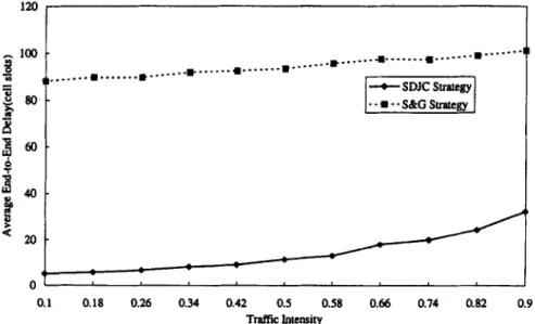
Average end-to-end delay versus trafJic intensity. The traffic intensities vary from 0.1 to 0.9. From the simulation results shown in Fig. 13, the SDJC gives a better average end-to-end delay than S&G. The major reason is that an incoming cell of connection i will become eligible immedi- ately if C,,(i) = 0. It removes the extra synchronization delay and leads to a smaller queuing delay.
End-to-end cell delay distribution. In order to evaluate the end-to-end delay under heavy load, the total traffic intensity is increased to nearly 1.0 in each node. In S&G strategy, the end-to-end cell queuing delay is given as
D,=HT+~~=,Oi_l,i+d,, where -T<d,<T and
H = 4. Since source 0 (To = 15) passed through four nodes, every mismatch is equal to T0/2, thus the total end- to-end delay is within the interval of [75, 1041 cell slots and
_ ml - (‘___.._~_._---’ ~_...I % l .._....,.“‘-’ _*_....- i8 )_‘_..’ 5 , . . . . ._______*...-.‘- s ao- i?
Ei
I3zl60-
6#43-
%
2
20- 01 I 0.1 0.18 0.26 0.34 0.42 0.5 0.58 0.66 0.74 0.82 0.9 Traffic lotensityY.C. Chen et al./Computer Communications 21 (1998) 445-459 451
Fig. 14. End-to-end queuing delay distribution of source 0 under both SDJC and S&G strategies.
the delay-jitter is bounded by 2To. In SDJC strategy, the end-to-end delay is bounded by [4, 741 cell slots and the delay-jitter is bounded by (H + l)(Ts - l), as illustrated in Fig. 14. The simulation results demonstrate that the SDJC strategy provides a guaranteed service for the CBR traffic. Although SDJC has higher delay-jitter than S&G, its end-to- end delay is much lower. From the viewpoint of an end- system, SDJC can provide a better end-to-end performance with lower implementation complexity.
4.2.2. Comparison in end-to-end delay and delay-jitter of ADJC strategy and S&G
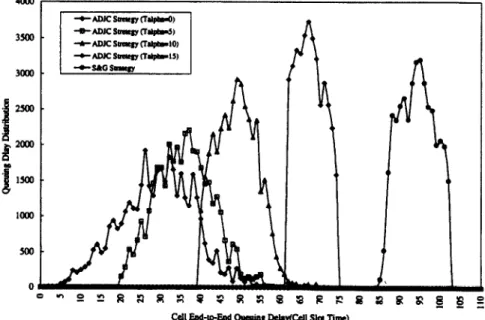
As illustrated in Fig. 15, the results of ADJC with differ- ent control parameter values (T,) show that the ADJC strat- egy provides a bounded end-to-end delay and supports adaptive delay-jitter control for SST connections. Since source 0 (To = 15) passed through four nodes, if the delay
control parameter T, is set to 1, 5, 10, and 15, then the total end-to-end delay is within the interval of [4, 741, [20, 741, [40,74], and [60,74] respectively. By using ADJC strategy, we can flexibly control the delay-jitter for various CBR services in ATM networks.
4.3. Numerical analysis
Assume a source traffic is regulated as an SST pattern with time-frame T and there are H hops in the routing path, the S&G framing strategy guarantees bounded end-to-end
delay, delay-jitter and cell-loss-free transmission for each connection. However, S&G may lead to extra synchroniza- tion delay. In S&G, the maximum end-to-end queuing delay is bounded by 2HT + T and the delay-jitter is bounded by 2T. While the RCSP/DJ provides a nearly optimal delay- jitter control, the delay-jitter is bounded by T. However, it
458 Table 1
Y.C. Chen et al./Computer Communications 21 (1998) 445-459
Comparison among different traffic control strategies
Advantages Disadvantages
S&G strategy
RCSP/DJ TCRM ADJC strategy
Bounded queuing delay [ZHT - T, 2HT + TJ. Bounded Large total end-to-end delay. Extra synchronization delay is
delay jitter [0, 2T]. introduced. Assigned frame size is inflexible.
Bounded queuing delay [0, HT]. Bounded delay-jitter [0, r]. Very difficult to realize. Bounded queuing delay [0, HTJ Bounded delay-jitter [0, HT]. Larger delay-jitter.
Adaptive bounded queuing delay. Flexible delay-jitter control. Introducing control parameter T,. Overhead of the RM cell. Maximum delay-jitter [0, HT]. Minimal delay-jitter [0, T].
needs to pass the delay information (cell eligible time) from
node to node and to synchronize the clock time of all
intermediate nodes precisely, which is very difficult in a
wide-area ATM network. The TCRM provides a guaranteed end-to-end queuing delay HT for real-time traffic, although it provides a lower average queuing delay HT than S&G, but the delay-jitter HT is worse than that in S&G. In the ADJC
strategy, the maximum end-to-end queuing delay is
bounded by HT and we can adaptively control the delay-
jitter down to T. Our proposed strategy removes the extra
synchronization delay and allows arbitrary time-frame
sizes. The advantages and disadvantages between other
schemes and our proposed method are listed in Table 1.
[2] D. Hong, T. Suda, Congestion control and prevention in ATM net- work, IEEE Network Magazine July ( 199 1) IO- 16.
[3] J.J. Bae, T. Suds, Survey of traffic control schemes and protocols in ATM network, Proceedings of IEEE 79 (2) ( 199 1) 170- 189. [4] H. Kroner, G. Hebuteme, P. Boyer, A. Gravey, Priority management
in ATM switching nodes, IEEE Journal on Selected Areas in Com- munications 9 (3) (1991) 418-427.
[5] D.W. Peter and V.S. Frost, Nested threshold cell discarding for ATM overload control: optimization under cell loss constraints, IEEE INFOCOM ‘91, pp. 1403-1412.
[6] J. Turner, Managing bandwidth in ATM networks with bursty traffic, IEEE Network September (1992) 50-58.
[7] J. Turner, B-ISDN/ATM traffic and congestion control, IEEE Net- work Magazine September (1992) 28-37.
[S] A. Demers, S. Keshav, S. Shenker, Analysis and simulation of a fair queueing algorithm, J. Intemetworking Research and Experience October (1990) 3-26.
5. Conclusion
In ATM networks where flow control and error control are end-to-end, the networks may be vulnerable to overload/
congestion that severely degrades their performance. It has
been suggested that congestion problems can be solved by
reactive control as well as preventive control strategies. The
combination of access control and transmission control
provides a more effective control method. Therefore, we
propose a simple rate control technique and a feasible
implementation method to guarantee the performance of
delay-sensitive traffic in broadband networks. In our
proposed strategy, the traffic pattern of each connection
can be maintained as close to the smoothed source traffic
(i.e. SST) as possible throughout the network. The major
advantages of the ADJC strategy is the improvement of the
end-to-end delay by removing the extra synchronization
delay, and the flexibility to control the delay-jitter. Although the ADJC strategy needs an RM cell to carry the delay
information To of the upstream node, the overhead can be
neglected for a CBR connection. The ADJC strategy can be
implemented in most switching architectures. By using the
ADJC strategy, a bounded end-to-end delay and a flexible
delay-jitter can be well controlled.
[9] A. Parekh, R. Gallager, A generalized processor sharing approach to flow control in integrated services networks: the single-node case, IEEE Transactions on Networking 1 (3) (1993) 344-357.
[IO] L. Zhang, Virtual clock: a new traffic control algorithm for packet switching networks, Proc. ACM SIGCOMM ‘90, Philadelphia, PA, September 1990, pp. 19-29.
[ Ill H. Zhang, Service disciplines for guaranteed performance service in packet-switching networks, Proceedings of the IEEE 83 (10) (1995)
1374-1396.
[ 121 H. Zhang, Providing end-to-end performance guarantees using non- work-conserving disciplines, Computer Communications 18 (10) (1995) 769-781.
[ 131 H.J. Chao, N. Uzun, An ATM queue management handling multiple delay and loss priority, IEEE/ACM Transactions on Networking 3 (6) (1995) 652-659.
[ 141 H.J. Chao, N. Uzun, A VLSI sequencer chip for ATM traffic shaper and queue management, IEEE J. Solid-State Circuits 27 (11) (1992) 1634-1643.
[I51 S. Golestani, A framing strategy for congestion management, IEEE Journal on Selected Areas in Communications 9 (7) (1991) 1064- 1077.
1161 S. Golestani, Congestion-free for communication in high speed packet network, IEEE Transactions on Communications 39 (12) (1991) 1802-1812.
References
[ 171 L. Trajkovic, S. Golestani, Congestion control for multimedia ser- vices, IEEE Network Magazine September (1992) 20-26.
[ 181 C. Kalmanek, H. Kanakia and S. Keshav, Rate controlled services for very high-speed networks, IEEE Global Telcommun. Conf., San Diego, CA, December 1990, pp. 300.3.1-300.3.9.
[I91 H. Zhang and D. Ferrari, Rate-controlled static priority queueing, IEEE INFGCOM ‘93, San Francisco, CA, April 1993, pp. 227-236. [20] H. Zhang, Providing end-to-end performance guarantees using non-
work-conserving disciplines, Computer Communications 18 (IO) (1995) 7699781.
[I] J. Golestani, Multimedia traffic management principles for guaranteed [21] S.-K. Kweon and K.G. Shin, Traffic-controlled rate-monotonic ATM network performance, IEEE Journal on Selected Areas in Com- priority scheduling of ATM cells, IEEE INFGCOM ‘96, pp. 655-
Y.C. Chen et al./Computer Communications 21 (1998) 445-459 459 [22] R. Brown, Calendar queue: a fast O(1) priority queue implementation flow control in integrated services networks: the multiple node case,
for the simulation event set problem, Communications of the ACM 3 1 IEEE Transactions on Networking 2 (2) (1994) 137- 150.
(10) (1988) 1220-1227. [25] S. Golestani, A self-clocked fair queueing scheme for broadband [23] M.W. Garrett, A service architecture for ATM: from applications to applications, IEEE INFOCOM ‘94, Toronto, CA, June 1994,
scheduling, IEEE Network May/June (1996) 6- 14. pp. 636-646. [24] A. Parekh, R. Gallager, A generalized processor sharing approach to