國立交通大學
材料科學與工程學系
博士論文
成長於氧化鎂基板上之氮氧化鈦與碳氧化鈦磊晶薄
膜結構與特性研究
Structure and properties of epitaxial titanium oxynitride
and titanium oxycarbide films on MgO substrate
研究生: Do Thi Hien
指導教授: 張立 教授
國立交通大學
材料科學與工程學系
博士論文
成長於氧化鎂基板上之氮氧化鈦與碳氧化鈦磊晶薄
膜結構與特性研究
Structure and properties of epitaxial titanium oxynitride
and titanium oxycarbide films on MgO substrate
研究生: Do Thi Hien
指導教授: 張立 教授
成長於氧化鎂基板上之氮氧化鈦與碳氧化鈦磊晶薄膜結構與特性
研究
Structure and properties of epitaxial titanium oxynitride and titanium
oxycarbide films on MgO substrate
研究生: 杜氏賢 Student: Do Thi Hien
指導教授: 張立 教授 Advisor: Dr. Li Chang
國立交通大學
材料科學與工程學系
博士論文
A thesis
Submitted to Department of Materials Science and Engineering College of Engineering
National Chiao Tung University in partial Fulfillment of Requirements for the Degree of Doctor of Philosophy
in
Materials Science and Engineering
October 2013
Hsinchu, Taiwan, Republic of China
I
成長於氧化鎂基板上之氮氧化鈦與碳氧化鈦磊晶薄
膜結構與特性研究
研究生:杜氏賢 (Do Thi Hien) 指導教授:張立博士
國立交通大學材料科學與工程學系博士班
摘要
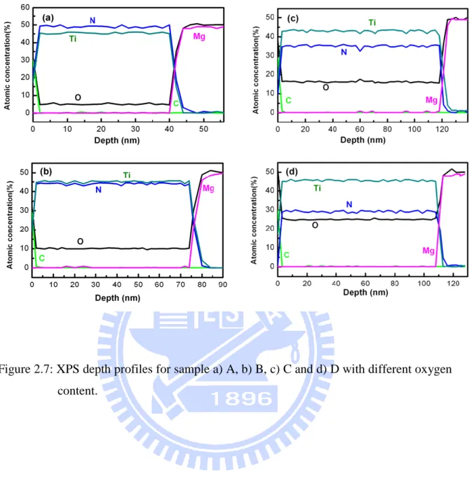
氮氧化鈦(TiNxOy) 與碳氧化鈦(TiCxOy)由於其獨特的特性,在科技領域中已成為非 常受人矚目的材料。氮氧化鈦與碳氧化鈦由於具有相對新穎的組成,因此仍需要許多 的研究與分析工作,以了解其相關特性。儘管目前已有許多相關的研究,但因欠缺單 晶材料,而無法獲得基本性質。因此,在本研究中,將於 MgO 基板上沉積高品質之 TiNxOy與 TiCxOy 磊晶薄膜,並探討 TiNxOy在氫電漿蝕刻下的蝕刻狀況與穩定性。同 時針對 TiNxOy與 TiCxOy 磊晶薄膜的機械性質,進行深入的研究。本論文研究的 TiC0.47O0.69與 TiNxOy磊晶薄膜是使用脈衝雷射沉積法(pulsed laser deposition)於 MgO 基板上成長,薄膜具有不同化學的組成 (0.63 < x < 1.11, 0.1 < y < 0.55) 。 X 光 光 電 子 能 譜 (X-ray photoelectron spectroscopy, XPS) 及 X 光 繞 射 (X-ray diffraction, XRD)的分析結果顯示,以異質磊晶方式沉積於 MgO 基板上的 TiNxOy 與 TiCxOy 薄膜,其結晶性佳,並且均處於完全壓縮應變(fully compressive strain)的狀態之 下。所沉積的 TiNxOy與 TiC0.47O0.69 磊晶薄膜也都具有良好的導電特性。經由穿透式電
子顯微鏡(Transmission electron microscopy, TEM)的分析得知,TiNxOy與 TiC0.47O0.69 薄
膜內所含有的差排密度低,而原子力顯微鏡(Atomic force microscopy, AFM)的分析則顯 現兩者的薄膜表面均相當平整。當氧的含量增加,會減少 TiNxOy薄膜的導電性及晶格 常數,殘留應力也因此隨之而減小。
II
另一方面,對 TiNxOy 磊晶薄膜進行氫電漿處理。掃描式電子顯微鏡(Scanning electron microscopy, SEM)、AFM 以及 XPS 的分析結果顯示,TiNxOy的蝕刻與化學穩 定性與氫氣壓力大小有著強烈的關係。當氫氣壓力低於 40 Torr 時,TiNxOy仍然相當穩 定並保有其良好的結晶性。隨著壓力的增加,將可能導致倒角錐狀之蝕刻凹坑的形成。 關於 TiNxOy與 TiC0.47O0.69薄膜的機械性質,則使用奈米壓痕技術(nanoindentation)
來加以量測。以 TiNxOy 薄膜而言,其薄膜硬度(H)與楊氏係數(E)分別約為 17~26 GPa 以及 355~430 GPa,不論是薄膜硬度或是楊氏係數,均隨著氧含量的增加而減小,隨 著氮含量的增加而變高。而硬度與楊氏係數降低的同時,也發現其殘留壓應力亦會變 小。另外在 TiCxOy 薄膜方面, TiC0.47O0.69經過量測所得到的數值為 H ~ 21 ± 1.7 GPa
III
Structure and properties of epitaxial titanium oxynitride
and titanium oxycarbide films on MgO substrate
Student: Do Thi Hien Advisor: Dr. Li Chang
Department of Materials Science and Engineering
National Chiao Tung University
Abstract
Titanium oxynitride (TiNxOy) and titanium oxycarbide (TiCxOy) have become very attractive materials in the field of science and technology due to their unique properties. Because titanium oxynitride and titanium oxycarbide are of relatively new compositions, therefore, they still need more works and characterizations to explore their properties. Although there have been relatively large amounts of studies on titanium oxynitrides and titanium oxycarbides, some basic properties of the films have not been established due to the lack of single crystals. Therefore, in the thesis, we report the epitaxial growth of TiNxOy and TiCxOy films on MgO substrates. We also study the stability and etching of TiNxOy in hydrogen plasma. Mechanical properties of epitaxial TiNxOy and TiCxOy films are especially investigated.
The epitaxial TiC0.47O0.69 and TiNxOy films with different chemical composition (0.63 < x < 1.11, 0.1 < y < 0.55) were deposited on MgO substrates by pulsed laser deposition method. X-ray photoelectron spectroscopy (XPS) and X-ray diffraction (XRD) analyses showed that the TiNxOy and TiC0.47O0.69 films are heteroepitaxially grown on MgO with good
crystallinity and they are under compressive strain. Both deposited epitaxial TiNxOy and TiCxOy are very electrically conducting. Transmission electron microscopy analyses showed that TiNxOy and TiCxOy films contain a low density of dislocations. Atomic force microscopy (AFM) revealed very smooth surfaces of TiNxOy and TiC0.47O0.69 films. The increase in
oxygen content reduces electrical conductivity and the lattice parameters of TiNxOy films, and residual stress decreases as a consequence.
IV
Epitaxial TiNxOy films were treated under hydrogen plasma generated from microwave. Scanning electron microscopy (SEM), AFM, and XPS results showed that the stability and etching of TiNxOy strongly depend on hydrogen gas pressure. TiNxOy was very chemically stable and remained with good crystallinity under hydrogen pressure below 40 Torr. With increase of pressure, it may lead to the formation of etch pits in inverse pyramid shape.
The mechanical properties of TiNxOy and TiC0.47O0.69 films were characterized using
nanoindentation. For TiNxOy films, hardness H and Young’s modulus E are about 17 - 26 GPa and 355 - 430 GPa, respectively; both H and E decrease with increasing oxygen content and increase with increasing nitrogen content; a reduction of H and E with decreasing residual compressive stress are also observed. Titanium oxycarbide film with composition of TiC0.47O0.69 shows the value of H ~ 21 ± 1.7 GPa and E ~ 390 ± 6.4GPa.
V
Acknowledgements
I am indebted to many people who contributed in several ways to this thesis, and supported me with their cooperation and timely help.
I particular, I wish to express my sincere gratitude to my research advisor Prof. Li Chang, for providing me an opportunity to work in his research group. I thank his for unique personal support in every aspect of the experimental work, for all the stimulating ideas, all the deep discussion, for providing support in preparation of various manuscripts for publications, presentations, posters and for the time he spent reviewing this thesis. He has been a great mentor with his enthusiasm, understanding and willingness to help students professionally and personally.
I am extremely thankful to Dr. Y.H. Han, Dr. J.C. Tian, Dr. C.Y. Peng, Mr. Tzu-Chun Yen, Dr. W.W. Lin, Dr, W.C. Chen, Dr. J.Y. Chen, Mr. K.A. Chiu, Mr. Y.S. Shih, Ms. Y.C. Chen, Ms. P.Y. Lin, and L.L. Wei for serving my experimental supports and their precious suggestions to my study. I would like to thanks to all my lab members for their friendship and help.
Most importantly, I wish to thank my entire family like to dedicate this work to my family. I especially thank my husband for his endless love and supports throughout my life. Most of all, I wish to thank my 9-month old daughter for giving me so much happiness, confidence, and motivation in every single day of my life.
I would like to thank everybody who was important to the successful realization of thesis, as well as expressing my apology that I could not mention personally one by one.
The financial support of my Ph. D research work by a grant from the NCTU and NSC, Taiwan, ROC is gratefully acknowledged.
VI
Contents
Abstract (in Chinese)---I Abstract (in English)--- ---III Acknowledgements---V Contents ---VI Abbreviations ---IX Table Captions---XI Figure Captions---XII Chapter 1: Introduction---1 1.1. Background---1
1.1.1. Structure and properties---1
1.1.2. Applications---8
1.1.3. Film growth---8
1.2. Motivation--- 9
1.3. Structure of thesis---10
References---12
Chapter 2: Epitaxial growth of titanium oxynitride and titanium oxynitride films on MgO substrate---19
2.1. Introduction---19
2.2. Experimental---21
2.2.1. Pulsed laser deposition system---21
2.2.2. Experimental flowcharts and deposition parameters and material analysis methods---21
2.2.3. Instruments---24
2.2.3.1. X-ray photoelectron spectroscopy---24
2.2.3.2. X-ray diffraction (XRD)---25
2.2.3.3. Transmission electron microscopy (TEM)---27
2.2.3.4. Atomic Force Microscopy (AFM)---29
2.2.3.5. Electrical conductivity measurement---30
2.3. Structure and properties of epitaxial TiNxOy films on MgO (001) substrates---30
2.3.1. Chemical composition---30
2.3.2. Microstructure ---34 2.3.3. Determination of the strain/stress tensors in the epitaxial TiNxOy/MgO
VII
layers by x-ray diffraction---42
2.3.4. Surface morphology---52
2.3.5. Electronic properties---52
2.4. Structure and properties of epitaxial TiCxOy films on MgO (001) substrates---53
2.4.1. Chemical composition---53
2.4.2. Microstructure---56
2.4.3. Determination of the strain/stress tensors in the epitaxial TiCxOy/MgO layers by x-ray diffraction---61
2.4.4. Surface morphology---62
2.4.5. Electronic properties---63
2.5. Summary---63
References---65
Chapter 3: Nanoindentation studies of epitaxial TiNxOy (001) and TiCxOy (001) films on MgO (001)---69
3.1. Introduction---69
3.2. The theory of nanoindentation---69
3.3. Substrate effects and the limitation of conventional Oliver-Pharr method---71
3.4. Li and Vlassak model---73
3.5. Application of Li and Vlassak model for determining hardness and Young’s modulus of epitaxial TiNxOy and TiCxOy films grown on MgO (001) substrate--75
3.5.1. Experimental ---75
3.5.2. Results and discussions---76
A. TiNxOy /MgO---76
B. TiCxOy /MgO---84
3.7. Summary---87
References---88
Chapter 4: Stability and etching of TiNxOy in hydrogen microwave plasma---91
4.1. Introduction---91
4.2. Experimental---91
4.3. Stability and etching of TiNxOy: morphology and mechanism---92
4.4. Summary---103
References---104
Chapter 5: Conclusions and future works---105
VIII 5.2. Future works---106 Appendix A---108 Appendix B---111 List of publications---118 Autobiography---119
IX
Abbreviations
TiN Titanium nitride TiC Titanium carbide TiNxOy Titanium oxynitride TiCxOy Titanium oxycarbide CVD Chemical vapor deposition PLD Pulsed laser deposition MOCVD Metal organic chemical vapor deposition MgO Magnesium oxide AFM Atomic force microscopy XPS X-ray photoelectron spectroscopy TEM Transmission electron microscopy HRTEM High-resolution transmission electron microscopy XRD X-ray diffraction Ar Argon nm nanometer cm centimeter eV electron volt FWHM Full width at half maximum RSM Reciprocal space maps XRR X-ray reflectivity MPCVD Microwave plasma chemical vapor deposition
X
H Hardness
XI
Table Captions
Table 1.1: Structural and thermal, electrical, and mechanical properties of TiN, TiC,
TiO, and MgO---3
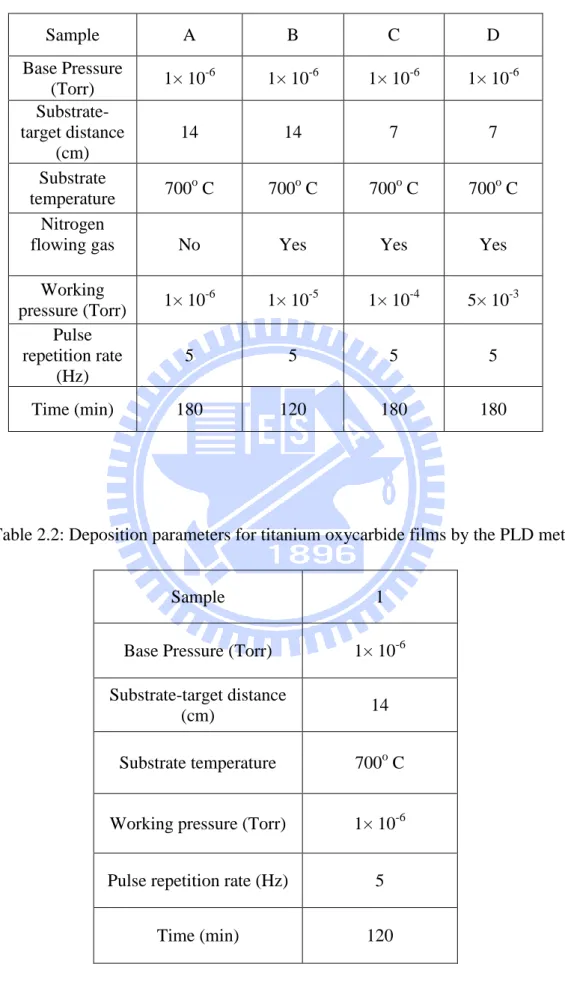
Table 2.1: Deposition parameters for titanium oxynitride films by the PLD method
---23
Table 2.2: Deposition parameters for titanium oxycarbide films by the PLD method-
---23
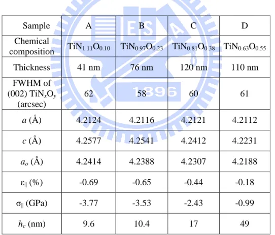
Table 2.3: Chemical composition, thickness, in-plane a, out-of plane c, and relaxed ao lattice parameters, FWHM of (002) TiNxOy, in-plane residual strain ε|| and
stress σ||, and critical thickness hc of TiNxOy films---35
Table 2.4: XRD measured and calculated strains in 5 [hkl] directions for the
TiN1.11O0.10 film---45
Table 2.5: XRD measured and calculated strains in 5 [hkl] directions for the
TiN0.97O0.23 film---46
Table 2.6: XRD measured and calculated strains in 5 [hkl] directions for the
TiN0.81O0.38 film ---46
Table 2.7: XRD measured and calculated strains in 5 [hkl] directions for the
TiN0.63O0.55 film ---47
Table 2.8: The principal stress σ1, σ2, and σ3, maximum shear stress τmax, and the critical shear stress τcrit [2.22] of TiNxOy films---51
Table 2.9: XRD measured and calculated strains in 5 [hkl] directions for the
TiC0.47O0.69 film---61
Table 2.10: The principal stress σ1, σ2, and σ3, and maximum shear stress τmax of the TiC0.47O0.69 film---62
Table 3.1: The hardness and Young’s modulus of TiNxOy films calculated by using Li-Vlassak method ---77
Table 3.2: The hardness and Young’s modulus of TiC0.47O0.69 film calculated by
using Li-Vlassak method---85
XII
Figure Captions
Figure 1.1: NaCl structure of TiN, TiC, and TiO---2
Figure 1.2: Calculated Ti–C phase diagram [1.15]---4
Figure 1.3: Calculated Ti–N phase diagram [1.16]---4
Figure 1.4: Calculated Ti-O phase diagram [1.18]---5
Figure 1.5: Pseudoternary phase diagram of the TiN-TiC-TiO system at 1100 °C (from Neumann et al. [1.28]). The cell parameters ao of Ti(C,N,O) are indicated. The lines separate zones of similar ao---6
Figure 1.6: Structure of a) TiN, b) TiC, c) TiNxOy, and d) TiCxOy viewing from [001] direction. TiNxOy and TiCxOy structures are made by substituting oxygen atoms for nitrogen and carbon atom, respectively---7
Figure 2.1: The PLD process---20
Figure 2.2: A schematic view of the PLD system---21
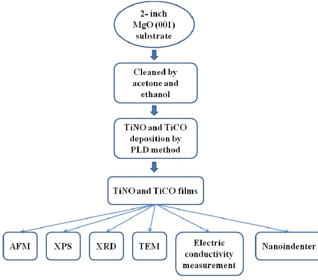
Figure 2.3: Experimental flowcharts of deposition and characterization of epitaxial of titanium oxynitride and titanium oxycarbide films on MgO (001) substrate-- ---22
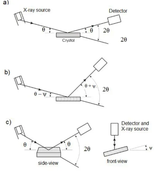
Figure 2.4: X-ray a) symmetric scan, b) asymmetric scan, and c) skew-symmetric scan techniques---26
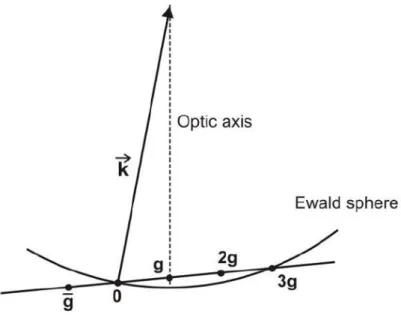
Figure 2.5: Ewald sphere constructions and the diffraction patterns for one intense diffraction spot with a) Kikuchi line runs exactl y through its corresponding spot g (s = 0), and b) the excess Kikuchi line lies outside its corresponding diffraction spot g (s > 0)---28
Figure 2.6: 3g condition for the WBDF image. The g refection is in the optical axis with a large excitation error---29
Figure 2.7: XPS depth profiles for sample a) A, b) B, c) C and d) D with different oxygen content ---31
Figure 2.8: XPS spectra for Ti-2p of samples A, B, C and D after Ar sputtering for one minute. The spectra are deconvoluted into components of titanium nitride, titanium oxynitride, and titanium dioxide.---32
Figure 2.9: XPS spectra for N-1s of samples A, B, C and D after Ar sputtering for one minute. The spectra are deconvoluted into components of titanium nitride and titanium oxynitride---33
XIII
Figure 2.10: XPS spectra for O-1s of samples A, B, C and D after Ar sputtering for one minute. The spectra are deconvoluted into components of titanium
oxynitride and titanium dioxide---34
Figure 2.11: XRD 2θ-θ scans for four TiNxOy films ---36
Figure 2.12: High-resolution XRD 2θ-θ scans for epitaxial TiNxOy films with different chemical composition deposited on MgO substrates --- 36
Figure 2.13: XRD -scan of {022} reflections for TiNxOy films grown on MgO substrate, showing epitaxial relationship between the film and the substrate is TiNxOy(001)//MgO(001) and TiNxOy[100]//MgO[100] ---37
Figure 2.14: Reciprocal space maps of the asymmetric (113) MgO and (113) TiNxOy reflections with different composition of a) TiN1.1O0.10 , b) TiN0.97O0.23,
c) TiN0.81O0.38 and d) TiN0.63O0.55 ---38
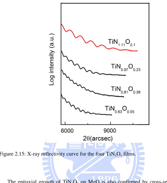
Figure 2.15: X-ray reflectivity curve for the four TiNxOy films ---40
Figure 2.16: Cross-sectional HRTEM images of a) sample A and b) sample B along [100] zone axis showing sharp and smooth interfaces between TiNxOy and MgO (indicated by arrows). No misfit dislocations at the interfaces can be observed over the range of 12-14 nm ---41
Figure 2.17: a) Cross-sectional TEM image of sample A in [100] bright-field and the corresponding diffraction pattern at the film/substrate interface. Cross -
sectional bright-field TEM images of sample A under two-beam condition of b) g = 002 and c) g = 022 ---42
Figure 2.18: Definition of the coordinate system for the specimen Si and the laboratory
system Li . The incident beam, the diffracted beam, and the normal to the
diffracting planes L3 are in the same plane. The sample can be rotated on the diffractometer in ϕ and in ψ. S3 is normal to the sample surface, and S1 and S2 are in the sample surface---43
Figure 2.19: Coordinate settings---44 Figure 2.20: Mohr's circles for a three-dimensional state of stress---49 Figure 2.21: The maximum shear stresses τmax acting on the plane that bisects the angle
between the planes in which the maximum σ1 and minimum σ3 principal
stresses act ---51
Figure 2.22: AFM images of TiNxOy surface for a) sample A, b) sample B, c) sample C,
XIV
Figure 2.23: XPS spectra for (a) C-1s, (b) Ti-2p, and (c) O-1s, as a function of Ar sputtering time ---55 Figure 2.24: XPS depth profile for TiCxOy film deposited on MgO---56
Figure 2.25: XRD (a) 2θ-θ scan and (b) -scan for TiC0.47O0.69 film deposited on MgO
(001)---57
Figure 2.26: XRD ϕ-scan of {022} planes for TiC0.47O0.69 film on MgO (001) substrate,
showing that epitaxial relationship between the film and the substrate is
TiCO(001)//MgO(001) and TiCO[100]//MgO[100]--- 58
Figure 2.27: X-ray reflectivity curve for the deposited TiC0.47O0.69 film ---58
Figure 2.28: Reciprocal space map of the asymmetric (113) for TiC0.47O0.69 film on
MgO---59
Figure 2.29: Cross-sectional HRTEM image along [100] zone axis showing a sharp interface between TiC0.47O0.69 and MgO. No misfit dislocations are
observed at the interface over the range of 15 nm ---60
Figure 2.30: AFM image of TiC0.47O0.69 film surface ---63
Figure 3.1: (a) A typical load-displacement curve and (b) the deformation pattern of an
elastic-plastic sample during and after indentation ---71
Figure 3.2: Schematic diagrams of a) sink-in (hard films/soft subtrates) and b) pile-up
(soft films/hard substrates) indentations ---72
Figure 3.3: Contour plot of log10(
2
) as a function of Ef and for the TiNxOy/MgO sample. The unit of 2 is in nm2 ---78
Figure 3.4: The Young’s modulus of TiNxOy films as a function of h/t (indentation depth/film thickness) obtained by using Li-Vlassak method, together with the Young’s modulus of MgO substrate. The results obtained using Oliver-Pharr method are presented for comparison---80
Figure 3.5: The hardness of TiNxOy films as a function of indentation depth calc ulated by using both Li-Vlassak and Oliver-Pharr methods. The hardness value of MgO substrate is also included---81
Figure 3.6: The dependence of the hardness and Young’s modulus of TiNxOy films on chemical composition---82
Figure 3.7: Evolution of the DOS of the titanium oxynitrides (NaCl structure) with the
composition [3.23]---83
XV
residual compressive stress ---84
Figure 3.9: Contour plot of log10(
2
) as a function of Ef and for the TiC0.47O0.69/MgO
sample. The unit of 2 is in nm2---85
Figure 3.10: The hardness of TiC0.47O0.69 film as a function of indentation depth
calculated by using both Li-Vlassak and Oliver-Pharr methods. The hardness value of MgO substrate is also included---86
Figure 3.11: The Young’s modulus of TiC0.47O0.69 film as a function of h/t (indentation
depth/film thickness) obtained by using Li-Vlassak method, together with the Young’s modulus of MgO substrate. The results obtained using Oliver-Pharr method are presented for comparison---87
Figure 4.1: AFM images of (a) as-grown TiNxOy films and (b) TiNxOy film after hydrogen plasma treatment at pressure of 40 Torr for 90 min (sample 1)----94
Figure 4.2: AFM images of TiNxOy after etching at (a) 60 Torr for 30 min (sample 2), 80 Torr for (b) 30 min (sample 3) and (c) 60 min (sample 4); (d) cross-sectional SEM image of TiNxOy after etching at 80 Torr for 150 min (sample 5)---95
Figure 4.3: The distribution of the etch size and etch depth at (a) 60 Torr for 30 min,
80 Torr for (b) 30 min, (c) 60 min, and (d) 150 min---96
Figure 4.4: XPS depth profiles for (a) as-grown TiNxOy film and (b) sample 1---99
Figure 4.5: High-resolution XPS spectra for (a) Ti-2p and (b) O-1s as function of Ar
sputtering time of as-grown TiNxOy and sample 1. The spectra were deconvoluted into components using Voigt curve fitting---100
Figure 4.6: XRD 2θ-θ scans for (a) as-grown TiNxOy and (b) sample 1. The corresponding XRD -scan of (002) TiNxOy is displayed in the inset---102
Figure 4.7: X-ray reflectivity curves for TiNxOy films before and after treatment at 40 Torr for 90 min---102
1
Chapter 1
Introduction
1.1. Background
1.1.1. Structure and properties
Titanium nitride (TiN), titanium carbide (TiC), and titanium monoxide TiO belong to the class of so-called refractory metal compounds. They are all known as hard materials and crystallize in rock salt NaCl structure with close lattice constants [1.1]. Figure 1.1 shows the structure of TiN, TiC, and TiO. Generally, titanium compounds have high melting points and extreme hardness such as covalent crystals and they also have interesting optical, electronic, catalytic and magnetic properties. Table 1.1 presents the structure, and thermal, electrical, and mechanical properties of TiN, TiO, and TiC. Among those compounds, TiN and TiC possess many similarities in physical properties such as excellent electrical and thermal conductivity, low coefficient of friction, and high corrosion and oxidation resistance [1.1].
In terms of chemical bonding, TiNx, TiCx, and TiOx are found to exist not only in the stoichiometric (x = 1) form, but also in the nonstoichiometric form with x < 1 (substoichiometric form) and x > 1 (overstoichiometric form) [1.2-6]. Those compounds can exist in wide composition ranges while still retain their NaCl cubic structure (0.6 < x < 1.2 for TiNx [1.7-9], 0.48 < x < 1 [1.10, 11] for TiCx, and 0.51 < x < 1.26 for TiOx [1.12, 13]); and the composition have strong effects on properties of those titanium compounds. In TiOx structure, 10 – 15 % vacancies are found at both Ti and O lattice sites [1.12, 13], while only vacancies in C sublattices are reported in TiCx structure [1.10, 11]. In substoichiometric TiNx structure, the main point defects are N vacancies, while overstoichiometric TiNx structure contains both Ti vacancies and N interstitials [1.9].
2
Figure 1.1: NaCl structure of TiN, TiC, and TiO.
Figure 1.2 shows the Ti-C phase diagram from the most recent assessment by Frisk using Calphad method [1.14, 15]. In these works the δ phase is treated as a solution phase and modeled with a two-sublattice model, (Ti)1(C, Va)1, where Ti completely
occupies one sublattice and C partially occupies the other, thus leaving vacancies Va. Carbon and vacancies form a solid solution on the second sublattice and any ordering at low temperature is ignored in the model. Both α-Ti (HCP) and β-Ti (BCC) have low solubility of carbon. At low carbon content the δ-TiCx phase boundary is quite steep, which hints that the phase field is limited by the formation of an almost stoichiometric (fixed composition) compound. Figure 1.3 shows the Ti-N phase diagram [1.14, 16] also using Calphad method. Compared to the Ti–C phase diagram in Fig. 1.2, both the α-Ti and β-Ti phases dissolve much more nitrogen than carbon. The δ-TiNx phase is similar to the δ-TiCx phase and δ-TiNx is usually modeled in the same way as the carbide phase. The δ-TiNx phase field is wider than the phase field of δ-TiCx and, moreover, an ordered phase, ε-Ti2N, having the anti-rutile structure [1.17] appears at low temperature. Figure 1.4
3
Table 1.1: Structural and thermal, electrical, and mechanical properties of TiN, TiC, TiO, and MgO. Titanium nitride TiN Titanium carbide TiC Titanium monoxide TiO Magnesium oxide MgO
Structure NaCl NaCl NaCl NaCl
Lattice constant 4.2417 Å (PDF 38-1420) 4.317 Å (PDF 89-3828) 4.1770 Å (PDF 8-117) 4.211 (PDF 89-4248) Density 5.22 g/cm 3 [1.1, 19] 4.93 g/cm3 [1.1] 4.95 g/cm3 [1.20] 3.58 g/cm³ Melting point 2930 °C [1.1, 19] 3160 °C [1.1] 1750 °C [1.20] 2852 °C Thermal conductivity 19.2 W.m−1.K−1 [1.1, 19] 17.14 - 30.93 W.m−1.K−1 [1.21] - 5 – 60 W.m−1.K−1 Thermal expansion coefficient 9.35 × 10⁻⁶ K−1 [1.1, 19] 4.1 × 10⁻⁶ K−1 [1.21] - 13 x 10-6 K-1 [1.22] Vickers hardness 18-21 GPa [1.1, 19] 26 – 31 GPa [1.21, 23] - 10 GPa [1.24, 25] Modulus of elasticity 533 GPa for [002] 416 GPa for [111] [1.26] 439 GPa [1.21] [1.23] 400 GPa [1.13] 300 GPa [1.24, 25] Electrical resistivity 21.7 µΩ.cm [1.27] 55 µΩ.cm [1.28] 190 µΩ.cm [1.29] -
4 Figure 1.2: Calculated Ti–C phase diagram [1.15].
5
Figure 1.4: Calculated Ti-O phase diagram [1.18].
It is noticed that the group IV B metals such as titanium present pseudoternary systems of the type “TiO - TiN – TiC” [1.30]. This system shows substitutional solid solutions including “TiN-TiO”, “TiC-TiO”, and “TiN-TiC”, which correspond to extensive monophasic zones. The solid solutions, named Ti(N,C,O,) have the same cubic crystalline structure with that of TiN, TiC and TiO phases. The unit-cell parameter ao of Ti(N,C,O) phase depends on the TiC, TiO and TiN content. Figure 1.5 shows the pseudoternary phase diagram “TiO–TiN–TiC” proposed by Neumann et al.[1.31]. The monophasic zone covers the whole diagram at temperatures higher than 1100 °C. This zone corresponds to the Ti(C,N,O) phase. The cell parameter ao varies between 4.12 Å and 4.32 Å. The monophasic zones cover in part of the TiN-TiO and TiC-TiO axes in this system. Thus, the subsystems “TiN–TiO” and “TiC–TiO” present titanium oxynitride Ti(N,O) and titanium oxycarbide Ti(C,O), respectively. These oxynitride and oxycarbide have the same cubic structure of Ti(N,C,O) with ao depending on TiN, TiC, and TiO content. The binary systems Ti(N,O) and Ti(C,O) have recently attracted many attentions. As stated above, TiNx, TiCx, and TiOx generally exist in nonstoichiometric forms, and therefore titanium oxynitride and titanium oxycarbide have always found to exist in
6
nonstoichiometric form of TiNxOy and TiCxOy (with y ≤ 1 - x or y ≥ 1 – x) instead of TiNxO1-x and TiCxO1-x, respectively. Due to the fact that oxygen has high reactivity with
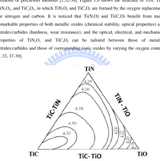
titanium, TiNxOy and TiCxOy are usually formed by the addition of oxygen to the TiN and TiC matrix, in which oxygen replaces nitrogen and carbon sublattice. This process can be carried out through the oxidation of TiN and TiC, or simultaneous mixing of elements or precursors methods [1.32-36]. Figure 1.6 shows the structure of TiN, TiC, TiNxOy, and TiCxOy, in which TiNxOy and TiCxOy are formed by the oxygen replacement for nitrogen and carbon. It is noticed that Ti(N,O) and Ti(C,O) benefit from many remarkable properties of both metallic oxides (chemical stability, optical properties) and nitrides/carbides (hardness, wear resistance); and the optical, electrical, and mechanical properties of TiNxOy and TiCxOy can be tailored between those of metallic nitrides/carbides and those of corresponding ionic oxides by varying the oxygen content [1.33, 37-39].
Figure 1.5: Ternary phase diagram of the TiN-TiC-TiO system at 1100 °C (from Neumann et al. [1.31]). The cell parameters ao of Ti(C,N,O) are indicated. The lines separate zones of similar ao.
It has shown that TiNxOy and TiCxOy still retains their NaCl crystal structure with a wide range of x and y [1.40, 41]). Therefore, similar to TiN and TiC, the slip systems in
7
TiNxOy and TiCxOy are mainly 1/2<110> {110}, and may also be {100}, {111}, and {112} [1.42]. The substitution of oxygen for nitrogen/carbon atoms could result in the changes in their structures as well as electronic structure and mechanical properties. Indeed, TiN and TiC contain both covalent and ionic bonding. The changes in oxygen and nitrogen/carbon content result in changes of covalent and ionic contribution to the bond in the TiNxOy and TiCxOy compounds. This is due to the difference in valence electrons of carbon (four valence electrons), nitride (five valence electrons), and oxygen (six valence electrons) [1.41, 43] that can result in the change of overlapping of atomic orbital.
Figure 1.6: Structure of a) TiN, b) TiC, c) TiNxOy, and d) TiCxOy viewing from [001] direction. TiNxOy and TiCxOy structures are made by substituting oxygen atoms for nitrogen and carbon atom, respectively.
Magnesium oxide (MgO) is also one of the most important materials used in the manufacturing of refractories. MgO is an insulator, and it is very chemically and physically stable at high temperature that is similar to TiC, TiN, and TiO. The physical and mechanical properties of MgO are shown in Table 1.1. MgO also has NaCl structure and its lattice constant is very close to those of TiC, TiN, and TiO. Therefore, MgO has
8
been widely used as substrate for the deposition of high-quality TiN, TiC, TiNxOy, and TiCxOy films.
1.1.2. Applications
Titanium oxynitride and titanium oxycarbide possess many interesting properties of both titanium nitritrde/carbide and titanium oxide. Therefore, those compounds have been widely used in a wide range of applications such as decorative and wear-resistant coating, and electronic devices [1.33, 37-39, 44]. Owning to excellent optical properties, titanium oxynitride has been used transparent IR window electrodes [1.37], solar collector devices [1.34, 37], electrical switchable windows [1.45], and photocatalysis [1.46]. In comparison with TiN, titanium oxynitride has shown new interesting properties that can be used as biomaterials [1.47, 48], memory devices [1.49]. In addition, titanium oxynitride nanocrystals with NaCl (rock-salt) structure especially show ultraviolet light emission in photoluminescence spectra at room temperature contrasted with TiN case [1.50].
1.2.3. Film growth
TiN films have been widely grown by pulsed laser deposition (PLD) and magnetron sputtering on various substrates such as MgO, Si, glasses, and stainless steels [1.51-64]. A large amount of scientific works about the deposition of polycrystalline [1.51-55] and epitaxial [1.56-64] TiN films have been reported. Epitaxial TiN has been successfully grown on MgO [1.56, 57, 59, 62] and Si [1.58, 60, 61, 63, 64] substrates. The best quality of epitaxial TiN films on MgO was reported in ref. [1.59], in which the full width at half maximum (FWHM) of the TiN(200) peak in ω-rocking curve scan was found to be 0.13o. In case of epitaxial TiN on Si substrate, the best quality was found in ref. [1.58], in which the FWHM the TiN (200) reflection is 0.47o.
TiC films have been grown by various processes such as chemical vapor deposition (CVD), pulsed laser deposition (PLD), magnetron sputtering, and evaporation on various substrates such as MgO, Si, graphite, and stainless steels [1.65-73]. Similarly to TiN, there have been many reports on polycrystalline [1.65-68] and epitaxial [1.69-72] TiC films. Epitaxial TiC films were found to be widely deposited on MgO [1.70-72], 6H-SiC [1.69], and Si [1.73] substrates. The best quality of epitaxial TiC with FWHM was found to be 0.63o on MgO [1.72], and 2.5o on Si [1.73].
9
TiNxOy films have been deposited by various processes, including oxidation of TiN [1.32], nitridation of TiO2 [1.74], and simultaneous mixing of elements or precursors
methods such as magnetron sputtering [1.33], evaporation [1.34], metal organic chemical vapor deposition (MOCVD) [1.35], and pulsed laser deposition (PLD) [1.36]. Similarly, most of TiCxOy films have been grown by chemical vapor deposition (CVD) and magnetron sputtering [1.38, 39, 75-78]. In those processes, both TiNxOy and TiCxOy films usually grown on various substrates such as Si, glass, and steel. In most cases, however, TiNxOy and TiCxOy films have been reported to be amorphous or polycrystalline. There is the fact that epitaxial growth of TiNxOy and TiCxOy films has been rarely studied in contrast with the case of TiN and TiC. To our best knowledge, there are no reports on the epitaxial TiNxOy and TiCxOy films, and no bulk and single crystal TiNxOy and TiCxOy are available.
1.2. Motivation
Titanium oxynitride and titanium oxycarbide are of relatively new compositions. Therefore, they still need many works and characterizations to explore an accomplished knowledge on their properties. One of the most interesting properties is the effects of oxygen on structure, electrical and mechanical properties of TiNxOy and TiCxOy. In fact, there have been large amounts of scientific studies on the optical and electrical properties, and chemical compositions of titanium oxynitride and titanium oxycarbide. However, most of those studies focused on polycrystalline TiNxOy and TiCxOy films in contrast with epitaxial TiNxOy and TiCxOy films that has been rarely reported. This is due to the fact that TiNxOy and TiCxOy are very hard materials and are difficult to synthesize in bulk by several common deposition methods such as chemical vapor deposition (CVD), magnetron sputtering, and evaporation. Moreover, in order to obtain high-quality, especially epitaxial TiNxOy and TiCxOy films, those methods require a relatively high substrate temperature which may lead to serious problems for many applications. For hard materials such as TiN, TiC, TiNxOy and TiCxOy, mechanical properties are very important. The difficulty in deposition of epitaxial TiNxOy and TiCxOy also limited the chance to study mechanical properties of TiNxOy and TiCxOy due to the fact that mechanical properties depend on not only chemical composition but also microstructure, whereas microstructure of polycrystalline TiNxOy and TiCxOy films varies widely and is often uncharacterized. The deposition of epitaxial TiNxOy also can improve electrical conductivity and overcome the problem of fast grain boundary diffusion of dopants and
10
impurities along the columnar grains of the polycrystalline films [1.79-82]. Furthermore, study of epitaxial films can improve our understanding of basic properties of TiNxOy and TiCxOy. Growth of epitaxial TiNxOy and TiCxOy films is also helpful for etching study due to it can avoid the complicated etch effects from grain boundaries and orientations in polycrystalline films.
TiN, TiC, TiNxOy and TiCxOy films have been widely applied in hydrogen environment; but there is still a lack of understanding about the effect of hydrogen on those materials. Furthermore, studying the etching of those materials by pure hydrogen plasma could be helpful for the first understanding about the role of hydrogen in the patterning process using plasma containing atomic hydrogen such as Cl2/CHF3,
Cl2/Ar/CHF3, Cl2/N2/CHF3, Ar/CHF3, and CH4/H2 [1.83, 84]. Moreover, hydrogen
plasma treatment can be applied to the revelation of dislocation etch pits in TiN, TiC, TiNxOy and TiCxOy.
This thesis reports the successful growth of epitaxial titanium oxynitride and titanium oxycarbide films on MgO (001) substrates using pulsed laser deposition. The crystallinity, microstructure, chemical composition, and morphology of titanium oxynitride and titanium oxycarbide were investigated. The effect of oxygen on the lattice parameter, microstructure, electrical, and mechanical properties of TiNxOy was especially investigated. Mechanical properties of TiNxOy films were characterized by using nanoindentation. The nanoindentation data was then analyzed and simulated to exclude the substrate effect and then extract the accurate hardness and Young’s modulus of the films. The study of the effects of hydrogen microwave plasma on the stability and etching of titanium oxynitride films as function of gas pressure and treating time was also studied.
1.3. Structure of the thesis
The thesis consists of five chapters and is organized as follows: Chapter 2 presents experimental methods and procedures for growth of epitaxial TiNxOy and TiCxOy on MgO (001) substrates; surface morphology, chemical composition, microstructure, and electrical properties of TiNxOy and TiCxOy are also described. Chapter 3 shows the nanoindentation studies of epitaxial TiNxOy and TiCxOy films including the basic theory of nanoindentation, models to solve substrate effects, experimental procedures, and results. Chapter 4 shows the stability and etching of TiNxOy depending on the hydrogen
11
plasma treatment conditions. Finally, Chapter 5 presents conclusions of the present study as well as the future works.
12
References
[1.1] H.O. Pierson, Handbook of Refractory Carbides and Nitrides: Properties,
Characteristics, Processing and Applications, Noyes Publication, Westwood, New Jersey, USA, 1996.
[1.2] A. Czyzniewski, W. Precht, Deposition and some properties of nanocrystalline, nanocomposite and amorphous carbon-based coatings for tribological applications, J Mater Process Tech, 157 (2004) 274-283.
[1.3] S.H. Jhi, S.G. Louie, M.L. Cohen, J. Ihm, Vacancy hardening and softening in transition metal carbides and nitrides, Phys Rev Lett, 86 (2001) 3348-3351.
[1.4] A. Mani, P. Aubert, F. Mercier, H. Khodja, C. Berthier, P. Houdy, Effects of residual stress on the mechanical and structural properties of TiC thin films grown by RF sputtering, Surf Coat Tech, 194 (2005) 190-195.
[1.5] W. Precht, A. Czyzniewski, Deposition and some properties of carbide/amorphous carbon nanocomposites for tribological application, Surf Coat Tech, 174 (2003) 979-983. [1.6] K.E. Tan, A.M. Bratkovsky, R.M. Harris, A.P. Horsfield, D. NguyenManh, D.G. Pettifor, A.P. Sutton, Carbon vacancies in titanium carbide, Model Simul Mater Sc, 5 (1997) 187-198.
[1.7] P.E. Schmid, M.S. Sunaga, F. Levy, Optical and electronic properties of sputtered TiNx
thin films, J Vac Sci Technol A, 16 (1998) 2870-2875.
[1.8] J.H. Kang, K.J. Kim, Structural, optical, and electronic properties of cubic TiNx
compounds, J Appl Phys, 86 (1999) 346-350.
[1.9] P. Patsalas, S. Logothetidis, Optical, electronic, and transport properties of nanocrystalline titanium nitride thin films, J Appl Phys, 90 (2001) 4725-4734.
[1.10] V.N. Lipatnikov, A.I. Gusev, Dependence of the resistivity of nonstoichiometric titanium carbide TiCy on the density and distribution of carbon vacancies, Jetp Lett+, 70
(1999) 294-300.
[1.11] V.N. Lipatnikov, A. Kottar, L.V. Zueva, A.I. Gusev, Ordering effects in nonstoichiometric titanium carbide, Inorg Mater+, 36 (2000) 155-161.
[1.12] S.R. Barman, D.D. Sarma, Electronic-Structure of TiOx (0.8 < x < 1.3) with disordered
and ordered vacancies, Phys Rev B, 49 (1994) 16141-16148.
[1.13] Y.O. Ciftci, Y. Unlu, K. Colakoglu, E. Deligoz, The structural, thermodynamical and elastic properties of TiO, Phys Scripta, 80 (2009) 025601.
13
[1.14] D.A. Andersson, P.A. Korzhavyi, B. Johansson, First-principles based calculation of binary and multicomponent phase diagrams for titanium carbonitride, Calphad, 32 (2008) 543-565.
[1.15] K. Frisk, A revised thermodynamic description of the Ti-C system, Calphad, 27 (2003) 367-373.
[1.16] S. Jonsson, Z. Metallkd., 87 (1996) 691–702.
[1.17] E. Etchessahar, J.P. Bars, J. Debuigne, The Ti-N system - Equilibrium between the delta-phase, epsilon-phase and alpha-phase and the conditions of formation of the Lobier and Marcon metastable phase, J Less-Common Met, 134 (1987) 123-139.
[1.18] B.-J.Lee, N.Saunders, Thermodynamic evaluation of the Ti-Al-O ternary system, Z. Metallkd., 88 (1997) 152-161.
[1.19] D.S. Stone, K.B. Yoder, W.D. Sproul, Hardness and elastic-modulus of TiN based on continuous indentation technique and new correlation, J Vac Sci Technol A, 9 (1991) 2543-2547.
[1.20] N. Greenwood, A. Earnshaw, Chemistry of the Elements, Butterworth-Heinemann, 1997.
[1.21] J.F. Shackelford, W. Alexander, CRC Materials Science and Engineering Handbook, Taylor & Francis, 2010.
[1.22] C.S. Shin, D. Gall, N. Hellgren, J. Patscheider, I. Petrov, J.E. Greene, Vacancy hardening in single-crystal TiNx(001) layers, J Appl Phys, 93 (2003) 6025-6028.
[1.23] P.C. Kong, B. Pfender, Carbide, Nitride and Boride Materials Synthesis and Processing, Chapman and Hall, London, 1997.
[1.24] D. Caceres, I. Vergara, R. Gonzalez, Y. Chen, E. Alves, Nanoindentation on MgO crystals implanted with lithium ions, Nucl Instrum Meth B, 191 (2002) 154-157.
[1.25] K. Kurosaki, D. Setoyama, J.J. Matsunaga, S. Yamanaka, Nanoindentation tests for TiO2, MgO, and YSZ single crystals, J Alloy Compd, 386 (2005) 261-264.
[1.26] S. Nagao, K. Nordlund, R. Nowak, Anisotropic elasticity of IVB transition-metal mononitrides determined by ab initio calculations, Phys Rev B, 73 (2006) 144113.
[1.27] R.C. Weast, Handbook of Chemistry and Physics, CRC Press, Boca Raton, FL, 1990. [1.28] P. Ettymayer, W. Lengauer, Carbides: Transition Metal Solid State Chemistry, Wiley, 1994.
[1.29] C.N.R. Rao, W.E. Wahnsiedler, J.M. Honig, Plasma resonance in TiO, VO and NbO, J Solid State Chem, 2 (1970) 315-317.
14
[1.30] A.D. Mazzonia, M.S. Conconib, Synthesis of group IVB metals oxicarbides by carboreduction reactions, Materials Research, 5 (2002) 459-466.
[1.31] G. Neumann, R. Kieffer, P. Ettmayer, Über das System TiC-TiN-TiO, Monatshefte für Chemie,, 103 (1972) 1130-1137.
[1.32] J. Graciani, J.F. Sanz, T. Asaki, K. Nakamura, J.A. Rodriguez, Interaction of oxygen with TiN(001): N <-> O exchange and oxidation process, J Chem Phys, 126 (2007) 244713. [1.33] F. Vaz, P. Cerqueira, L. Rebouta, S.M.C. Nascimento, E. Alves, P. Goudeau, J.E. Riviere, Preparation of magnetron sputtered TiNxOy thin films, Surf Coat Tech, 174 (2003)
197-203.
[1.34] M. Lazarov, P. Raths, H. Metzger, W. Spirkl, Optical-constants and film density of TiNxOy solar selective absorbers, J Appl Phys, 77 (1995) 2133-2137.
[1.35] F. Maury, F.D. Duminica, TiOxNy coatings grown by atmospheric pressure metal
organic chemical vapor deposition, Surf Coat Tech, 205 (2010) 1287-1293.
[1.36] Y. Suda, H. Kawasaki, T. Ueda, T. Ohshima, Preparation of high quality nitrogen doped TiO2 thin film as a photocatalyst using a pulsed laser deposition method, Thin Solid
Films, 453 (2004) 162-166.
[1.37] M. Braic, M. Balaceanu, A. Vladescu, A. Kiss, V. Braic, G. Epurescu, G. Dinescu, A. Moldovan, R. Birjega, M. Dinescu, Preparation and characterization of titanium oxy-nitride thin films, Appl Surf Sci, 253 (2007) 8210-8214.
[1.38] A.C. Fernandes, P. Carvalho, F. Vaz, S. Lanceros-Mendez, A.V. Machado, N.M.G. Parreira, J.F. Pierson, N. Martin, Property change in multifunctional TiCxOy thin films: Effect of the O/Ti ratio, Thin Solid Films, 515 (2006) 866-871.
[1.39] L. Marques, H.M. Pinto, A.C. Fernandes, O. Banakh, F.V.M.M.D. Ramos, Optical properties of titanium oxycarbide thin film, Appl Surf Sci, 255 (2009) 5615-5619.
[1.40] A. Afir, M. Achour, N. Saoula, X-ray diffraction study of Ti-O-C system at high temperature and in a continuous vacuum, J Alloy Compd, 288 (1999) 124-140.
[1.41] J. Graciani, S. Hamad, J.F. Sanz, Changing the physical and chemical properties of titanium oxynitrides TiN1-xOx by changing the composition, Phys Rev B, 80 (2009)
184112-184122.
[1.42] D. Hull, D.J. Bacon, Introduction to dislocations, Butterworth-Heinemann, 2011. [1.43] L. Karlsson, L. Hultman, M.P. Johansson, J.E. Sundgren, H. Ljungcrantz, Growth, microstructure, and mechanical properties of arc evaporated TiCxN1-x (0 ≤ x ≤ 1) films, Surf
15
[1.44] D. Munteanu, R. Cozma, B. Borcea, F. Vaz, The influence of oxygen flow on the tribological behaviour and residual stress of TiCO thin-films, J Optoelectron Adv M, 8 (2006) 712-715.
[1.45] Y. Saito, M. Hirata, H. Tada, M. Hyodo, Electrically switchable window using a suspension of TiOxNy particles, Applied Physics Letters, 63 (1993) 1319-1321.
[1.46] R. Asahi, T. Morikawa, T. Ohwaki, K. Aoki, Y. Taga, Visible-light photocatalysis in nitrogen-doped titanium oxides, Science, 293 (2001) 269-271.
[1.47] Y.X. Leng, P. Yang, J.Y. Chen, H. Sun, J. Wang, G.J. Wang, N. Huang, X.B. Tian, P.K. Chu, Fabrication of Ti-O/Ti-N duplex coatings on biomedical titanium alloys by metal plasma immersion ion implantation and reactive plasma nitriding/oxidation, Surf Coat Tech, 138 (2001) 296-300.
[1.48] R.J. Koerner, L.A. Butterworth, I.V. Mayer, R. Dasbach, H.J. Busscher, Bacterial adhesion to titanium-oxy-nitride (TiNOX) coatings with different resistivities: a novel approach for the development of biomaterials, Biomaterials, 23 (2002) 2835-2840. [1.49] D.-H. Kang, D.-H. Ahn, M.-H. Kwon, H.-S. Kwon, K.-B. Kim, K.S. Lee, B.-k. Cheong, Lower voltage operation of a phase change memory device with a highly resistive TiON layer, Japanese Journal of Applied Physics, 43 (2004) 5243-5244.
[1.50] X.G. Yang, C. Li, B.J. Yang, W. Wang, Y.T. Qian, Optical properties of titanium oxynitride nanocrystals synthesized via a thermal liquid-solid metathesis reaction, Chem Phys Lett, 383 (2004) 502-506.
[1.51] N. Biunno, J. Narayan, S.K. Hofmeister, A.R. Srivatsa, R.K. Singh, Low-temperature processing of titanium nitride films by laser physical vapor-deposition, Applied Physics Letters, 54 (1989) 1519-1521.
[1.52] V. Craciun, D. Craciun, C. Ghica, L. Trupina, C. Flueraru, N. Nastase, Growth of thin transparent titanium nitride layers by reactive laser ablation, Appl Surf Sci, 138 (1999) 593-598.
[1.53] H.D. Gu, K.M. Leung, C.Y. Chung, X.D. Han, Room-temperature growth of high-purity titanium nitride by laser ablation of titanium in a nitrogen atmosphere, Surf Coat Tech, 110 (1998) 153-157.
[1.54] J.H. Huang, K.W. Lau, G.P. Yu, Effect of nitrogen flow rate on structure and
properties of nanocrystalline TiN thin films produced by unbalanced magnetron sputtering, Surf Coat Tech, 191 (2005) 17-24.
16
[1.55] J.M. Lackner, W. Waldhauser, R. Berghauser, R. Ebner, B. Major, T. Schoberl, Structural, mechanical and tribological investigations of pulsed laser deposited titanium nitride coatings, Thin Solid Films, 453 (2004) 195-202.
[1.56] N. Biunno, J. Narayan, A.R. Srivatsa, O.W. Holland, Laser deposition of epitaxial titanium nitride films on (100) MgO, Applied Physics Letters, 55 (1989) 405-407.
[1.57] J. Bottiger, J. Chevallier, J.H. Petersen, N. Schell, W. Matz, A. Mucklich, Observation of the growth mode of TiN during magnetron sputtering using synchrotron radiation, J Appl Phys, 91 (2002) 5429-5433.
[1.58] R. Chowdhury, X. Chen, J. Narayan, Pulsed-laser deposition of epitaxial Si/TiN/Si(100) heterostructures, Applied Physics Letters, 64 (1994) 1236-1238.
[1.59] T. Lee, H. Seo, H. Hwang, B. Howe, S. Kodambaka, J.E. Greene, I. Petrov, Fully strained low-temperature epitaxy of TiN/MgO(001) layers using high-flux, low-energy ion irradiation during reactive magnetron sputter deposition, Thin Solid Films, 518 (2010) 5169-5172.
[1.60] W.J. Meng, G.L. Eesley, Growth and mechanical anisotropy of TiN thin films, Thin Solid Films, 271 (1995) 108-116.
[1.61] J. Narayan, P. Tiwari, X. Chen, J. Singh, R. Chowdhury, T. Zheleva, Epitaxial growth of TiN Films on (100) silicon substrates by laser physical vapor deposition, Applied Physics Letters, 61 (1992) 1290-1292.
[1.62] N. Pryds, D. Cockburn, K. Rodrigo, I.L. Rasmussen, J. Knudsen, J. Schou, Growth of thin films of TiN on MgO(100) monitored by high-pressure RHEED, Appl Phys a-Mater, 93 (2008) 705-710.
[1.63] P. Tiwari, T. Zheleva, J. Narayan, Epitaxial growth of TiN Films on (100) silicon substrates by laser physical vapor deposition, Laser Ablation in Materials Processing : Fundamentals and Applications, 285 (1993) 349-354.
[1.64] T. Zheleva, K. Jagannadham, J. Narayan, Epitaxial growth in large-lattice-mismatch systems, J Appl Phys, 75 (1994) 860-871.
[1.65] G. Leggieri, A. Luches, M. Martino, A. Perrone, G. Majni, P. Mengucci, I.N. Mihailescu, Laser reactive ablation deposition of titanium carbide films, Thin Solid Films, 258 (1995) 40-45.
[1.66] P. Lin, C. Deshpandey, H.J. Doerr, R.F. Bunshah, N. Kaufherr, R. Nielsen, G. Fenske, Detailed characterization of TiC and TiN coatings prepared by the activated reactive
17
[1.67] Y. Suda, H. Kawasaki, K. Doi, S. Hiraishi, Formation and properties of TiC thin films by pulsed Nd/YAG laser deposition, Thin Solid Films, 374 (2000) 282-286.
[1.68] J.K. Tang, J.S. Zabinski, J.E. Bultman, TiC coatings prepared by pulsed laser deposition and magnetron sputtering, Surf Coat Tech, 91 (1997) 69-73.
[1.69] A.K. Chaddha, J.D. Parsons, G.B. Kruaval, Thermally stable, low specific resistance (130 × 10-5 Ωcm2) TiC ohmic contacts to n-type 6Hα-SiC, Applied Physics Letters, 66 (1995) 760-762.
[1.70] H. Hogberg, J. Birch, M.P. Johansson, U. Jansson, L. Hultman, Strain relaxation of low-temperature deposited epitaxial titanium-carbide films, J Cryst Growth, 219 (2000) 237-244.
[1.71] L. Norin, H. Hogberg, J. Lu, U. Jansson, J.O. Malm, Deposition of transition metal carbide superlattices using C60 as a carbon source, Applied Physics Letters, 73 (1998)
2754-2756.
[1.72] L. Norin, S. McGinnis, U. Jansson, J.O. Carlsson, Low temperature deposition of epitaxial titanium carbide on MgO(001) by co-evaporation of C60 and Ti, J Vac Sci Technol
A, 15 (1997) 3082-3085.
[1.73] W.H. Sheu, S.T. Wu, Epitaxial growth of TiC (002) on Si (001) by reactive magnetron sputtering at low temperatures, Jpn J Appl Phys 1, 37 (1998) 6094-6097.
[1.74] O. Diwald, T.L. Thompson, T. Zubkov, E.G. Goralski, S.D. Walck, J.T. Yates, Photochemical activity of nitrogen-doped rutile TiO2(111) in visible light, J Phys Chem B,
108 (2004) 6004-6008.
[1.75] G. Georgiev, N. Feschiev, D. Popov, Z. Uzunov, Titanium carbide thin-films obtained by reactive magnetron sputtering, Vacuum, 36 (1986) 595-597.
[1.76] J.E. Sundgren, B.O. Johansson, S.E. Karlsson, Mechanisms of reactive sputtering of titanium nitride and titanium carbide. 1. Influence of process parameters on film composition, Thin Solid Films, 105 (1983) 353-366.
[1.77] A.C. Fernandes, P. Carvalho, F. Vaz, N.M.G. Parreira, P. Goudeau, E. Le Bourhis, J.P. Riviere, Correlation between processing and properties of titanium oxycarbide, TiCxOy, thin
films, Plasma Process Polym, 4 (2007) S83-S88.
[1.78] A.C. Fernandes, L. Cunha, C. Moura, F. Vaz, P. Carvalho, E. Le Bourhis, P. Goudeau, J.P. Riviere, N.M.G. Parreira, The effect of bombarding conditions on the properties of
multifunctional Ti-C-O thin films grown by magnetron sputtering, Surf Coat Tech, 202 (2007) 946-951.
18
[1.79] N. Kumar, M.G. Fissel, K. Pourrezaei, B. Lee, E.C. Douglas, Growth and properties of TiN and TiOxNy diffusion-barriers in silicon on sapphire integrated-circuits, Thin Solid Films,
153 (1987) 287-301.
[1.80] W. Sinke, G.P.A. Frijilink, F.W. Saris, Oxygen in titanium nitride diffusion-barriers, Applied Physics Letters, 47 (1985) 471-473.
[1.81] N. Kumar, J.T. Mcginn, K. Pourrezaei, B. Lee, E.C. Douglas, Transmission electron-microscopy studies of brown and golden titanium nitride thin-films as diffusion-barriers in very large-scale integrated-circuits, J Vac Sci Technol A, 6 (1988) 1602-1608.
[1.82] R. Chowdhury, R.D. Vispute, K. Jagannadham, J. Narayan, Characteristics of titanium nitride films grown by pulsed laser deposition, J Mater Res, 11 (1996) 1458-1469.
[1.83] S.C. Abraham, C.T. Gabriel, J. Zheng, Performance of different etch chemistries on titanium nitride antireflective coating layers and related selectivity and microloading
improvements for submicron geometries obtained with a high-density metal etcher, J Vac Sci Technol A, 15 (1997) 702-706.
[1.84] J. Tonotani, T. Iwamoto, F. Sato, K. Hattori, S. Ohmi, H. Iwai, Dry etching characteristics of TiN film using Ar/CHF3, Ar/Cl2, and Ar/BCl3 gas chemistries in an
19
Chapter 2
Epitaxial growth of titanium oxynitride and
titanium oxycarbide films
on MgO substrate
2.1. Introduction
Titanium oxynitride and titanium oxycarbide films have been deposited by many methods such as CVD, MOCVD, magnetron sputtering, evaporation, and PLD. Among those methods, PLD has been widely used over the past decade and has been considered as an attractive alternative for the deposition of high-quality thin films because of its unique advantages. The main advantages of PLD are [2.1]:
(i) Conceptually simple: a laser beam vaporizes a target surface, producing a film with the same composition as the target.
(ii) Non-volatile targets
(iii) Multi-component target.
(iv) Multi-target or multi-layer or alloy films.
(v) Operated under any ambient gas over a broad range of gas pressure (from 0 – 1 Torr).
(vi) Easy of thickness control.
(vii) Generally of lower substrate temperature.
(viii) Cost-effective: one laser can serve many vacuum systems.
(ix) Fast: high quality samples can be grown reliably in 10 or 15 minutes. (x) Scalable: as complex oxides move toward volume production.
As shown in Fig. 2.1, the PLD process consists of three regimes: (i) Regime I: Laser-target interaction.
(ii) Regime II: Target to substrate gas phase transportation. (iii) Regime III: Deposition and film growth process.
20
Figure 2.1: The PLD process.
The regime II of gas transportation contains high ion/neutral ratio and many ionized species with high kinetic energy (about 10-100 eV). Therefore, PLD is particularly capable of deposition of many materials that are difficult to synthesize in bulk and by other deposition methods such as ceramics (YBCO, PZT, SBN), complex oxides, hard materials (including diamond/diamond like films, TiN, TiC, TiNxOy, TiCxOy, SiC…), and exotic alloys and multi-component films (Fe16N2, La1-xSrxMnO3). The film’s structure and
growth mechanism are strictly related to the conditions of plasma obtained by the interaction between targets and laser beam. Authors in ref. [2.2] have shown that in the plume produced from TiC targets, there is the presence of a large amount of ions with high kinetic energy including Ti+, Ti2+, and C+ ions. The neutral Ti was also obtained in the TiC plasma plume. In case of pulsed laser deposition of TiN by the irradiation Ti target in nitrogen gas, the plasma plume contains high-density of reactive species and high-energy ions such as Ti and Ti+, Ti2+, N+ , and N2+ [2.3, 4].
In this chapter, we present the detailed description of the experimental procedures for epitaxial growth of titanium oxynitride and titanium oxycarbide films on MgO (001) substrate using PLD. The crystallinity, microstructure, chemical composition, and morphology of titanium oxynitride and titanium oxycarbide are also studied. The effect of oxygen on the lattice parameter, microstructure, and electrical properties of TiNxOy was especially investigated. The residual strain and stress tensors of TiNxOy and TiCxOy films were also calculated.
21
2.2. Experimental
2.2.1. Pulsed laser deposition system
The deposition of titanium oxynitride and titanium oxycarbide films was carried out in a PLD system. The base pressure in this PLD system can reach 1x10⁻⁶ Torr. Figure 2.2 presents a schematic view of the PLD system. The basic structure of the PLD system consists of the following parts:
(i) The substrate stage can be heated up to 700oC.
(ii) A 2-inch target is placed opposite to a substrate stage at a distance of 14 cm. The target can be rotated to avoid pitting during deposition.
(iii) KrF (λ = 248 nm) laser beam is incident at an angle of 45o with respect to the target.
(iv) The PLD reactor chamber is made of stainless steel to sustain high temperature and pressure.
Figure 2.2: A schematic view of the PLD system.
22
Figure 2.3 shows the experimental flowcharts of deposition and characterization of epitaxial of titanium oxynitride and titanium oxycarbide films on MgO (001) substrates. Before titanium oxynitride and titanium oxycarbide films deposition, MgO substrates were heat-treated at 700oC for 30 minutes to obtain a smooth and clean surface. To obtain TiNxOy films with different chemical composition, a TiNO0.064 target was used, and the
deposition process was carried out under base pressure of 1 × 10⁻⁶ Torr and under nitrogen ambient gas of 10-3-10-5 Torr. Detailed deposition parameters are shown in Table 2.1. A TiCO0.5 target was used to deposit TiCxOy films, and deposition parameters for the TiCxOy films are showed in Table 2.2. After the deposition process had been completed, the substrate was cooled down to room temperature in 90 minutes.
Figure 2.3: Experimental flowcharts of deposition and characterization of epitaxial of titanium oxynitride and titanium oxycarbide films on MgO (001) substrate.
23
Table 2.1: Deposition parameters for titanium oxynitride films by the PLD method.
Sample A B C D Base Pressure (Torr) 1× 10 -6 1× 10⁻⁶ 1× 10⁻⁶ 1× 10⁻⁶ Substrate-target distance (cm) 14 14 7 7 Substrate temperature 700 o C 700o C 700o C 700o C Nitrogen
flowing gas No Yes Yes Yes Working pressure (Torr) 1× 10 -6 1× 10⁻⁵ 1× 10⁻⁴ 5× 10⁻³ Pulse repetition rate (Hz) 5 5 5 5 Time (min) 180 120 180 180
Table 2.2: Deposition parameters for titanium oxycarbide films by the PLD method.
Sample 1
Base Pressure (Torr) 1× 10⁻⁶ Substrate-target distance
(cm) 14
Substrate temperature 700o C Working pressure (Torr) 1× 10⁻⁶ Pulse repetition rate (Hz) 5
24
The deposited films were then analyzed by atomic force microscopy (AFM), x-ray photoelectron spectroscopy (XPS), x-ray diffraction pattern (XRD), transmission electron microscopy, Hall measurements, and nanoindenter. The results of nanoindentation as well as data analysis will be presented in Chapter 3.
2.2.3. Instruments:
2.2.3.1. X-ray photoelectron spectroscopy
X-ray photoelectron spectroscopy (XPS) is one of the most powerful techniques used in the surface, interface and thin film analysis. Of all the presently available instrumental techniques for surface analysis, XPS can generally do quantitative analysis with readily interpretable and the informative results of chemical analysis.
In an XPS experiment, the sample is irradiated by low energy X-rays in an ultra high vacuum environment. This causes photo-ionisation of the atoms at the specimen's surface: photoelectrons are emitted from the atomic energy levels with very specific Binding Energies and, consequently, with a very accurate spectral signature/fingerprint for all the elements from the Periodic Table and their chemical compounds. Quantitative data can be obtained from peak heights or peak areas. The quantitative sensitivity is in the range of (10-2 - 10-4) of a monolayer and the surface sensitivity is in the range of (2-100) monolayers (<0.5 - 20nm). From the results of this analysis, it is possible to infer which elements are present on the specimen, what their chemical states are (due to chemical shifts of the binding energy of the electron shells), and in what quantities they are present. The following quantitative results are obtained with errors <10% (and <5% for using well known standards): element relative concentrations, oxidation states relative concentrations, and chemical states relative concentrations.
In general, the basis advantages of XPS are: (i) Nondestructive
(ii) Surface sensitive (100 Å) (iii) Elemental sensitive
(iv) All elements (except for hydrogen and helium) (v) Quantitative
(vi) Chemical bonding information (vii) High information content
25
In this study, XPS was used to analyze the chemical composition of the deposited films and chemical states of titanium, nitrogen, carbon, and oxygen. XPS analyses were formed on a PHI Quantera SXM (ULVAC-PHI) system with monochromatic Al Kα radiation source. Argon ion with ion energy of 5keV was used for sputter profiling. For XPS quantitative analysis, the peak area was corrected with relative sensitivity factors from manufacture’s program and database. The spectra were deconvoluted into components using Voigt curve fitting.
2.2.3.2. X-ray diffraction (XRD)
X-ray diffraction (XRD) is a very important experimental technique that has long been used to address all issues related to the crystal structure of solids, including lattice constants, identification of unknown materials, orientation of single crystals, and ect. The Bede D1 system is a versatile high resolution X-ray diffractometer for the characterization of advanced materials. The system is most suitable for characterization of thin films, superlattices, and single crystal wafers, although it can also characterize other forms of materials. A range of parameters can be measured including thickness, composition, relaxation, strain, area uniformity, density, roughness, phase, crystalline texture, crystallinity, pore size and grain size.
In this study, a Bede D1 high-resolution x-ray diffractometer, equipped with two two-bounce Si 220 channel-cut collimator crystals (CCC), a dual channel Si 220 analyser crystal, and CuKα1 radiation (λ = 1.5406 Å), was used to investigate the crystallinity,
microstructure, and to calculate the strain/stress tensors of the films. Since CuKβ (λ = 1.39
Å) is also radiated from x-ray tube with Cu target, a Ni filter is used to eliminate the XRD peaks caused by the CuKβ. A symmetric 2θ-θ scan is used to determine the d-spacing of
the planes parallel to the sample surface [see Fig. 2.4a]. In this type of scan, the angle θ of the incoming beam with respect to the sample surface is varied, while simultaneously keeping the detector at an angle of 2θ with respect to the incoming beam. The angle θ at which a diffraction peak is observed, can then used to give the interplanar distance by using Bragg law. In order to determine the d-spacing of a set of planes that are tilted by an angle with respect to the sample surface, an asymmetric θ-2θ scan can be performed [see Fig. 2.4b]. As in the case of a symmetric scan, the detector is placed at an angle of 2θ with respect to the incoming beam. The incoming beam, however, makes an angle of ω with respect to the sample surface. Note that ω = θ – ψ, where is ψ the angle between
26
sample surface and the measured plane. An alternative to the asymmetric scan method is the skew-symmetric measuring geometry [Fig. 2.4c)]. As in the case of the symmetric scan, the incoming beam forms an angle θ with respect to the sample surface, while the detector is put at 2θ. The difference is that the sample is tilted over a fixed angle ψ around the axis that is parallel to the sample surface and the plane of the incoming and outgoing beam.
Figure 2.4: X-ray a) symmetric scan, b) asymmetric scan, and c) skew-symmetric scan techniques.
The XRD 2θ-θ scans, -scans, and asymmetric reciprocal space mapping (RSM) were performed under high-resolution mode set up. The set up of high-resolution mode consists of two Si 220 channel-cut crystals as the beam conditioner to provide four-bounce reflection and collimate the incident beam for 25 arcsec angular divergence, and a
![Figure 1.2 shows the Ti-C phase diagram from the most recent assessment by Frisk using Calphad method [1.14, 15]](https://thumb-ap.123doks.com/thumbv2/9libinfo/8477933.183870/20.892.160.781.151.783/figure-shows-diagram-recent-assessment-frisk-calphad-method.webp)
![Figure 2.16: Cross-sectional HRTEM images of a) sample A and b) sample B along [100] zone axis showing sharp and smooth interfaces between TiN x O y and MgO (indicated by arrows)](https://thumb-ap.123doks.com/thumbv2/9libinfo/8477933.183870/59.892.199.758.134.748/figure-cross-sectional-sample-showing-interfaces-indicated-arrows.webp)
![HPSH [ 氧化數平衡反應式係數 ]](data:image/gif;base64,R0lGODlhAQABAIAAAP///wAAACH5BAEAAAAALAAAAAABAAEAAAICRAEAOw==)