GPR reflection characteristics and depositional models of
mud volcanic sediments
—Wushanting mud volcano field,
southwestern Taiwan
Joseph Jinder Chow
a,⁎
, Su-Kai Chang
a, Ho-Shing Yu
baInstitute of Applied Geosciences, National Taiwan Ocean University, Keelung 20224, Taiwan, ROC bInstitute of Oceanography, National Taiwan University, Taipei, Taiwan, ROC
Received 25 June 2005; accepted 21 March 2006
Abstract
Ground penetrating radar (GPR) survey was conducted in the Wushanting mud volcano field (Yanchao, Kaohsiung) using a 500 MHz antennae, which allowed high-resolution imaging of subsurface structures. Seven GPR reflection characteristics are recognized. Sigmoid GPR reflection patterns resulted from a recent mud lobe deposited above an underlying older mud lobe front. Contorted GPR facies resulted from recent mud flow which encountered obstacles. Subparallel reflections resulted from mud volcano deposits of limited flowability, low velocity and gentle gradient. Hummocky reflection patterns are formed by interfingering of recent mud lobes building onto low land. Disrupted GPR facies were due to lateral breaks of continuity from mud cracks, which, according to field observation, can provide channels for erosion and form deeper erosion gullies. GPR time slices of different depths are rendered as a three-dimensional model. Approximately orbicular GPR reflection characteristics can indicate arcuate stacked mud lobe fronts of different periods. Some depositional models to explain GPR reflection characteristics can be founded upon observations of recent sedimentary phenomena. The models of this study may be applied to paleoenvironments and the depositional evolution of mud volcanoes in similar geological settings.
© 2006 Elsevier B.V. All rights reserved.
Keywords: Ground penetrating radar; Mud volcano; Reflection characteristics; Facies; Depositional model; Taiwan
1. Introduction
We define a mud volcano a topographical feature constructed mainly of mud, and other sedimentary constituents, which periodically or continuously vents liquid mud, including water, oil, and gas. Subsurface mud fluid mixing with gas rushes up along fissures
underground, blending with silt and groundwater on the way. Mud fluid is brought to the surface and stacks, forming a cone-shaped mud volcano landscape with central vents (Brown, 1990).
Mud volcanoes are not only distributed worldwide but also exist in a wide variety of tectonic environments, including passive continental margins (Hedberg, 1980) and continental interiors (Fertl and Tinmo, 1970), as well as transforming (Higgins and Saunders, 1973) and convergent plate boundaries (Reed et al., 1990).
The gas in mud volcanic mudstone of southwestern Taiwan has a close relationship with the decompounded
⁎ Corresponding author. Tel.: +886 2 24622192 x6510; fax: +886 2 24625038.
E-mail addresses:[email protected], [email protected](J. Jinder Chow).
0926-9851/$ - see front matter © 2006 Elsevier B.V. All rights reserved. doi:10.1016/j.jappgeo.2006.03.001
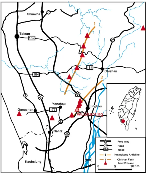
organic matter of the mudstone formation. The distribu-tion of most mud volcanoes is related to geologic structures and these are distributed along the axis of the Kutingkeng anticline and the Chishan faults (Fig. 1) (Wang et al., 1988).
Perhaps because there are few mud volcano outcrops, there is no published literature on the sedimentary structures of mud volcanoes at present. However, the Wushanting Mud Volcano Natural Landscape Reserved Area and its vicinity in Yanchao, Kaohsiung is a protected zone; absolutely no excavations or destructive investigations may be carried out here, so the research on subsurface structural features would be very difficult except by GPR. GPR research can offer consecutive subsurface data and is nondestructive, so it is a more
effective method for investigating this regional sedi-mentary structure than others.
Even GPR has potential to be a high-resolution stratigraphic tool, it has not been used much in sedimentation research. Most of its geological appli-cations have been related to environmental and glacial, groundwater and geotechnical issues (e.g.
Hanninen and Autio, 1992; Redman et al., 1994; Meyers et al., 1996; Young et al., 1998). Never-theless, GPR profiles delineating characteristic fea-tures of many coastal stratigraphic facies have been published since the early 1990s (Jol et al., 1994, 1996; van Heteren et al., 1994; Dott and Mickelson, 1995). Beres and Haeni (1991) and Smith and Jol (1992) depicted radar facies by analogy to seismic
reflection configurations. There is no published paper about the GPR reflection characteristics of mud volcanic stratigraphy.
The survey was carried out in grids around the mud volcano cone to research the diversity of lateral mudflows in the sedimentary structures. Also we hope that, by observing the different kinds of deposition in a recent mud volcano, we can establish a depositional model of GPR reflection characteristics. The establish-ment of characteristics of a reflected GPR signal of a mud volcano sedimentary structure could supply some reference for future researches on the paleoenviron-ments and depositional evolution of mud volcanoes. 2. Site description
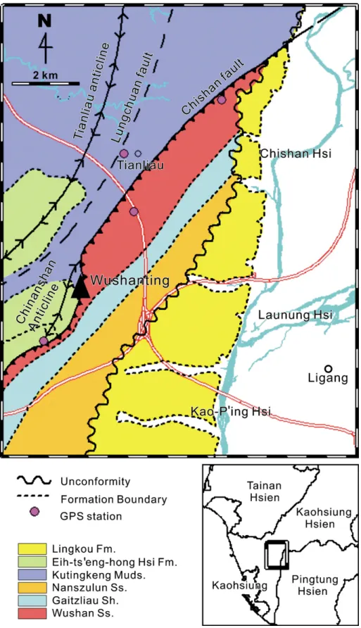
For southwestern Taiwan, mud volcanoes are mostly distributed along the Chishan fault. The Wushanting mud volcano field is also located on the Chishan fault (Fig. 1), a reverse fault. The solid matter of the Wushanting mud volcanoes mainly comes from the Kutingkeng Formation (Fig. 2), whose lithologic characteristics are gray mudstone intercalated with thin-bedded sandstone (Keng, 1981), and its clay particle content is about 58.57%. Therefore the sand content of mud fluid erupted from different mud volcanoes differs greatly (Wang et al., 1988). When a mud volcano erupts, the gasses emit to the surface mainly via different size bubbles, so the viscosity of the mud fluid can be judged by the size of the bubbles; small bubbles (0.5–3 cm) indicate low viscosity, and large bubbles (1–40 cm), high viscosity (Hovland et al., 1997).
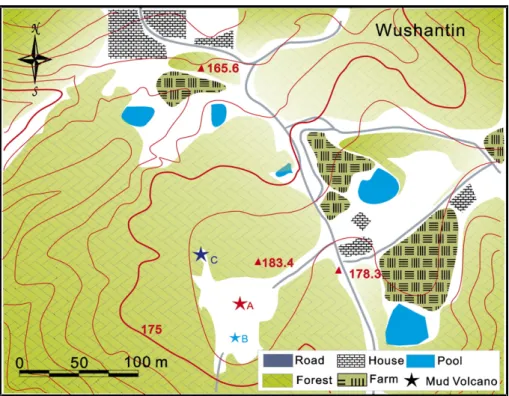
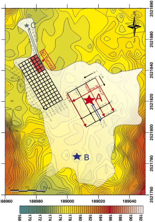
This mud volcano field is located in a 200 m × 150 m platform mostly covered with plants (Fig. 3). There are three main cone-shaped mud volcanoes in the platform, named as mud volcanoes A, B, and C. Mud volcanoes can be classified into five classes according to the viscosity of the mud fluid; and mud volcanoes A, B, and C is classified as “mud cone”. Mud volcano A is 3.5 m high, B is 3 m high, and mud volcano C is a 1-m-high miniature volcano which sits off in the northern part of the platform. There are more than 10 active mud volcanoes in the woods near the platform. Also there are other topographically well-developed mud volcano features in the nearby area, such as mud holes, mud basins and so on. In addition, they are all active.
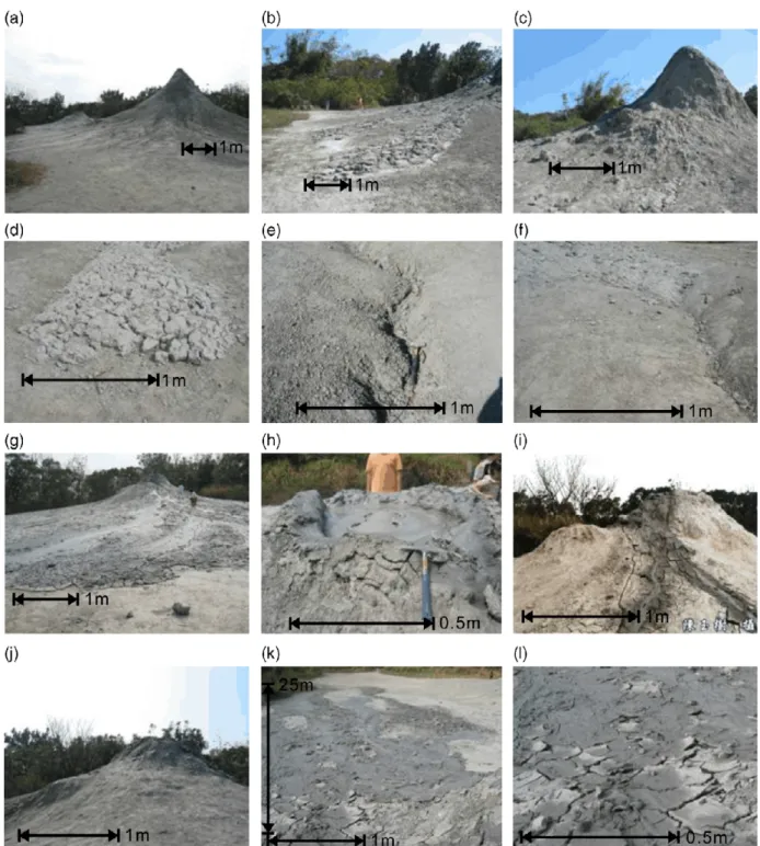
Mud volcano A (Fig. 3) is the largest mud volcano in the Wushanting mud volcano field (Fig. 4(a)). Mud volcano B, a 3-m-high mud volcano that sits 20–30 m south of mud volcano A (Fig. 3), is frequently active.
Ropy mud fluid and gas bubbles continue to erupt noisily from the mud (Fig. 4(g), (h)). However, after long periods of observation, we have found that the viscosity of mud fluid erupted from mud volcano B varies. Also, there appear to be two mud cones on mud volcano B,Fig. 4(i)) (Wang et al., 1988), but the smaller one has become inactive in recent years Fig. 4(j). The area around mud volcano B was covered by mud fluid which continued to erupt during our research, and the surface was so damp that the surveys were at times difficult to carry out (Fig. 4(g)). Nonetheless, it supplied well-developed and non-broken recent structures, so we were able to obtain comparisons of GPR characteristics and recent actual structures in the field. Although eruptions from mud volcano C are smaller in scale than those of mud volcano A, it nevertheless provides a good example of the evolution and development of a mud cone.
The mud shield shown inFig. 4(q), a developing mud volcano, is located in the woods about 20 m to the southwest of mud volcano B. By comparing it with the mud volcanoes A, B, and C, we can conclude that if this mud shield continues to develop, its scale may approach that of mud volcano C, and under suitable conditions, it could grow to be as grand as mud volcano A.Fig. 4(r) shows a mud hole located in the woods about 15 m to the east of mud volcano A. Another mud hole, shown in
Fig. 4(s), can be seen in a bamboo grove about 30 m to the southwest of mud volcano B. If it effuses out, the low-viscosity mud fluid of this mud hole may become a plate-like mud flow. The natural form of the Wushanting mud volcano is well preserved and the mud vent is dense and fixed. Besides Mud volcanoes A and B seem to be the largest, the most spectacular, and the most complete mud volcanoes in Taiwan and so were chosen to be the subjects of our study.
2.1. The deposition model of the mud volcano based on field observations
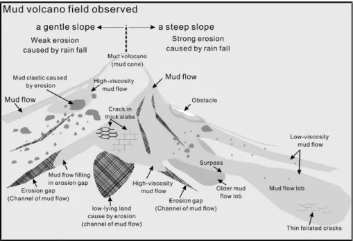
Based on field observations, the topographic features of mud volcanoes and the form of the mud flows at the mud cone can be generalized to the types of character-istics shown inFig. 5.
Mud flow runs along initially inclined strata and sediments on initially horizontal or inclined surfaces. Low-viscosity and more dilute mud fluid can run further as sheet-like mud flow (Figs. 4(k) and 5), becoming thin foliated cracked mud which curls upwards after drying due to the low viscosity (Fig. 4
(l)). But in high-viscosity mud flow, we can easily observe mud cracked in thick regularly shaped
geometric slabs (Figs. 4(m) and 5). Mud cracks, produced by drying of the mud fluid, can become filled by later flows. The regular geometric shape of some cracks (Figs. 4(n) and 5) can shape natural watercourses and aid rainwater to form erosion gaps (Figs. 4(o) and 5) on the mud volcano landscape. These erosion gaps could easily be filled by mud flows during a next eruption of the mud volcanoFigs. 4(f) and 5.
The font of a mud lobe can sometimes be a round area with a diameter of 70 m (Wang et al., 1988). Moreover, mud erupted to the upper part of mud volcano will sporadically flake off due to weathering and pile up around the mud volcano (Fig. 4(c)). Mud cracks appear as irregularly cracked platy structures (Figs. 4(d) and 5), and can be clearly seen on the mud lobe. Erosion gaps (Fig. 4(e)) resulting from rain erosion can also be seen on the cone flanks (Figs. 4(e) and 5). These erosion gaps could easily be filled by mud flow during a next eruption of the mud volcano (Figs. 4(f) and 5).
An erosion surface mainly results from rain erosion during rainfall, rather than mud flow, which is slow in velocity and lacks erosive power. Rain erosion gaps or even flutes (Figs. 4(e) and 5) that look like channel cuts can be seen on the cone surface around the mud volcano. As stacking from later eruptions goes on, the
mud volcano becomes higher and the gradient becomes steeper, strengthening the force of rain erosion, which in turn brings about an increase in the dip angle of the erosion surface. The gradient in the upper part of the cone of the mud volcano is steeper than that at the bottom; generally, the steeper the erosion surface, the stronger the erosion power. However, this statement is not absolute, as the power of erosion is related to the flow, which is controlled by the quantity of rainfall. The quantity of rainfall is an important factor affecting the sediment, and sedimen-tation, of the mud volcano in the study area, as is the viscosity of the mud fluid and the gradient. Never-theless, it is clear that mud flow not only makes use of these erosion gaps as passage (Fig. 4(e)) but also fills them in (Fig. 4(f)), the eroded lower gaps providing room for the mud flow to settle down.
The size and the scale of mud lobe prograding is directly influenced by the viscosity of mud flow. Moreover, when the mud fluid of a mud volcano flows, the moisture carried by the mud flow may be simultaneously absorbed by underlying dry mud. The farther the mud fluid flows, the ropier it becomes, and the slower it moves. We have found that when new mud flow has not dried up, the moisture of mud in the study area varies greatly. Even in such a small area like
Fig. 3. Mud Volcano Natural Landscape Reserved Area in Yanchao, Kaohsiung Wushanting Mud Volcano Natural Landscape Reserve Area. The area outlined in white is the study area, A, B, and C are mud volcanoes.
Wushanting, the debris carried by the mud fluid from each mud volcano is different in the size of the particles, the moisture of the mud fluid, and the viscosity as well.
In the field, we observed that a mud flow lobe is wider when it is still close to the mud volcano bottom (Figs. 4(b) and 5). At the upper part of a mud volcano,
Fig. 4. (a) Mud volcano A; (b) the mud volcano deposits; (c) mud sporadically flakes off due to weathering; (d) irregularly cracked platy structures; (e) erosion gaps; (f) erosion gaps filled by mud flow; (g) mud volcano B; (h) bubbles of gas erupt from its mud vent; (i) two mud cones originally on mud volcano B (photo by Yushu Chen); (j) the smaller one becomes inactive; (k) low-viscosity mud fluid; (l) mud flat sheets with curled edges; (m) mud cracks on high-viscosity mud; (n) regular geometric mud cracks; (o) erosion gaps; (p) mud volcano C; (q) a developing mud volcano; (r) a mud hole; (s) another mud hole.
where the gradient is steep, the mud fluid runs faster, so the lobe is narrower. When flow approaches the base of the mud volcano, the mud flow loses some of its energy and just flows in a sheet. This forms a wide and flat sedimentary structure profile for (Fig. 4(b)) at the mud volcano bottom which has a gentler slope. As evidenced by the field features of mud flow, the viscosity of the mud fluid impacts the ability to flow. So it should be the low-viscosity mud fluid (Figs. 4(k) and 5) that can reach the volcano base. However, because the moisture of the mud fluid is being absorbed by drier underlying earth or being evapo-rated into the air all the while the mud fluid is moving down, the viscosity of the mud fluid increases as it moves. Thus, mud flow will be ropier and slower as it moves on, which results in upwarping (Fig. 4(b), (d)) of the lobe front. Later, the upwarping of the lobe
front can be surpassed by more or newer mud flows
(Fig. 5). The phenomena of newer mud flow
surpassing the front of an older mud flow lobe can be easily observed in the field.
When mudflow encounters an obstacle, the part of the leading edge which contacts the obstacle will be hunched, or convex, due to the high viscosity. Even dry mud which has flaked off the upper part of the mud volcano due to weathering and piled up around the mud volcano (Figs. 4(c) and 5) can be an obstacle to mud flow.
3. GPR study
In this study, GPR data were collected using a PC-based digital pulse GSSI, SIR-II system mounted on a ski board. The mode of acquisition was zero-offset with
the transmitters and receivers mounted on the same package. In the preliminary stage of this survey, test profiles were collected to determine the best acquisition parameters to be used during the field survey in the Wushanting mud volcano field. The two available frequencies (200 and 500 MHz) as well as different gain functions and time ranges were tested. Although the penetrating depth of the 200 MHz GPR antenna was deeper than that of the 500 MHz antenna, we obtained higher resolution with the 500 MHz antenna, which remedied this shortcoming of shallower penetrating depth. The 500 MHz antenna was found adequate for mapping the structure of shallow subsurfaces in the area, with reasonable resolution. Several two-way travel-time ranges were tested and a time of 15 ns (two-way travel time) was found adequate; two-way travel time in excess of 15 ns was very feeble. As drier conditions return better results, the end of the dry season was chosen for data-collection to allow the GPR to reach the maximum depth of penetration.
Data processing was conducted using the GSSI RADAN processing software (RADAN for Windows, 2003). The processing flow was kept basic to avoid introducing any artifacts into the data. Initially, the header file was edited, followed by horizontal scale normalization to correct for differences in the speed of antenna movement during data collection. The data were then band-pass filtered to cut out very high and
very low frequencies. Kirchhoff migration was then applied to the data to move steeply dipping reflections to their true subsurface positions and to collapse hyper-bolic diffractions. Finally, a slight automatic gain control (AGC) function was applied to compensate for the loss in amplitude at depth due to spherical convergence, scattering attenuation, and dielectric loss, as well as amplitude loss occurring during some data processing steps, such as migration. Because the GPR data were not collected across a horizontal surface, static correction was necessary.
During data interpretation, it was necessary to convert the time section figures into depths. The velocity of the electromagnetic wave at the strata was required in GPR profile data to measure the section depth. When the surveying points were mainly homo-geneous, we were also able to use the Bar Test method of burying matters (such as a steel bar). The Bar Test was chosen because it allowed us to quickly and directly work out the velocity of electromagnetic wave at subsurfaces when the surveying sites were mainly homogeneous. Owing to differences in relative dielec-tric permittivity, the steel bar generated hyperbola-shaped reflection, by which two-way travel time could be used to work out the velocity of electromagnetic wave subsurface and the relative dielectric permittivity. If given the relative dielectric permittivity of the strata, the GSSI RADAN processing software (RADAN for
Fig. 5. This drawing of the model of mud volcano deposition is based on field observations. Both recent sedimentary structures and morphological phenomena observed onsite can be used to interpret different kinds of characteristics observed in surveys by GPR.
Windows, 2003) would convert the time profile into a depth profile.
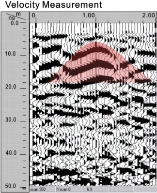
During the field velocity tests, the iron bar was not visible in the raw reflection displays. Only later after the data were processed with a background removal program and an automatic gain control applied was the bar visible (Fig. 6) as a reflection hyperbola, with its apex denoting the top of the bar. In this test the two-way travel time from the surface to the bar and back to the surface was measured at 6.9 ns, and the measured depth to the bar was 0.27 m. The relative electric permittivity then obtained in the profile analyses was 14.67. It is worth noticing that these surface layers were composed of mud which was wondrously dry because the surveys were performed during the end of the dry season.
4. GPR reflection characteristics
The internal reflection characteristics of mud volcano argillaceous sedimentary structures could be easily
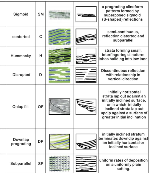
identified on the GPR profiles that were acquired around mud volcanoes (Fig. 7). Using the basic principles defined by Mitchum et al. (1977), Sangree and Widmier (1977), Vail et al. (1977), Roksandi'c (1978)and Bouma et al. (1987), a detailed interpreta-tion of data has allowed us to distinguish seven main types of reflection characteristics. The description of these reflection characteristics and a general inter-pretation used in the GPR surveys or in seismic stratigraphy follows.
4.1. Sigmoid
Sigmoid GPR configuration can be found in profile 27 (Fig. 9). A sigmoid progradational configuration is a prograding clinoform pattern formed by superposed sigmoid (S-shaped) reflections interpreted as strata with thin, gently dipping upper and lower segments, and thicker, more steeply dipping middle segments. The upper (topset) segments of the strata have horizontal or very low angles in the facies unit. The thicker middle (foreset) segments form lenses super-posed to allow successively younger lenses to be deposited laterally in a downdip direction, forming overall outbuilding or prograding patterns. The lower (bottomset) segments of the strata approach the lower surface of the facies unit at very low angles, and the seismic reflections show real or apparent downlap terminations as the strata terminate or become too thin to be recognized in seismic sections. In sections parallel with depositional strike, reflections indicate that strata are commonly parallel and concordant with unit boundaries.
4.2. Contorted
Contorted GPR configuration can be found in profile 28 (Fig. 10). A contorted reflection configuration consists of distorted subparallel reflections of high continuity. The upper segments of the strata were distorted more strongly while the lower segments of the strata were distorted less. This reflection pattern is interpreted as inner distortion, or distorted deposition by external force.
4.3. Hummocky
Hummocky GPR configuration can be found in profile 32 (Fig. 12). A hummocky clinoform reflection configuration consists of irregular discontinuous sub-parallel reflection segments forming a practically random hummocky configuration. The resolution is
Fig. 6. The velocity analysis: the hyperbola-shaped reflection apex gave a surface reflection electromagnetic wave velocity 0.08 m/ns. During the field velocity tests, the iron bar was not visible in the original reflection displays. Only later, after the data were processed with a background removal program and an automatic gain control applied, was the bar visible as a reflection hyperbola, with its apex denoting the top of the bar.
low, approaching the limit of seismic resolution. The reflection pattern is generally interpreted as strata forming small, interfingering, clinoform lobes building into shallow areas.
4.4. Disrupted
Disrupted GPR configuration can be found in profile 28 (Fig. 10). A disrupted reflection configuration consists of parallel or subparallel reflections. Both the upper segments of the strata and the underlying layer possess favorable continuity with the disrupted seg-ments, but there will be discontinuous reflections between layers in the disrupted segments and the reflection breaks show continuity with the upper and the underlying segments.
4.5. Onlap fill
Onlap GPR configuration can be found in profiles 27, 28, 30 and 32 (Figs. 9–12). Onlap is baselap in which an initially horizontal stratum laps out against an initially inclined surface, or in which an initially inclined stratum laps out to updip against a surface of greater initial inclination.
4.6. Downlap prograding
Downlap GPR configuration can be found in profile 28, and 30 (Figs. 10 and 11). Downlap is baselap in which an initially inclined stratum terminates to downdip against an initially horizontal or inclined surface.
Onlap and downlap are indicators of hiatuses rather than erosional hiatuses. Successive terminations of strata at their depositional limits along the initial depositional surface produce an increasing hiatus in the direction of onlap or downlap, which can be used to judge the erosion surface.
4.7. Subparallel
Subparallel GPR configuration can be found in profiles 27, 28, 30 and 32 (Figs. 9–12). Subparallel configurations may occur in shale drape-and-fill units with several external forms. This pattern suggests uniform rates of deposition on a uniformly subsiding shelf or stable basin plain setting.
5. The GPR profiles
Considering influencing factors such as whether instrument access would be successful and whether the surface had been covered by recent mud flow (surveys cannot be performed in the wet surface), we chose mud volcano A as the best site for GPR data-collection.
The gradient of the northeast slope of mud volcano A is gentler than any other slope. Limited by the landscape, the survey area was lined out as follows (Fig. 8).
Confined herein by the page layout, in order to show the comparison between the GPR reflection character-istics and the sedimentary structures, we have only brought forward the primary radar profiles. After displaying the data, we found that some data were better displayed in Line scan and others were better in Wiggle. Therefore, for more favorable display quality, both line scan and Wiggle were used in profile displays. 5.1. Profile 27
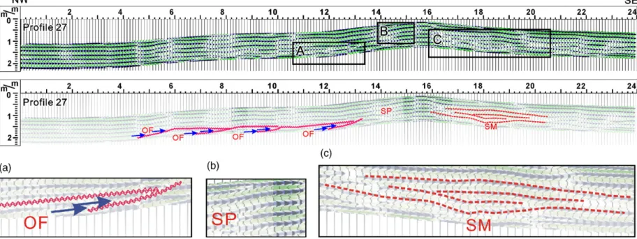
Profile 27 (Fig. 9) is located at the northeast base of mud volcano A (Fig. 8profile 27). We can see that there are onlap fill reflection characteristics in the left side of the profile. We were able to estimate some erosion surfaces by using a decrease of amplitude. The onlap reflection characteristics of the erosion surface were of low angle and level reflections. Such homogeneous infilling was of sheet-like deposits generated by mud flow at the low-angle slope base of the mud volcano. Mud flow is slow and lacks erosive power when it flows at the mud volcano base, which is usually gentle in gradient, and we maintain that the erosion surface was mainly generated by rainfall. More interpretation will be shown in profile 28. Sigmoid GPR reflection
character-istics could be observed in the right side of the profile, where GPR reflections evidence sedimentary structures generated by mud flow.
5.2. Profile 28
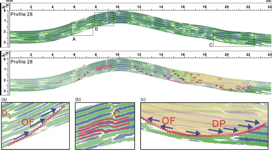
Profile 28 (Fig. 10) lies at the northeast flank of mud volcano A (Fig. 8, profile 28). Here, Onlap fill GPR reflection characteristics were also discovered, but what is different is that the erosion surface of onlap fill was steeper than the erosion surface in profile 27(Fig. 9). The steeper the erosion surface was, the stronger the erosion effect was. This pattern corresponds to part of the mud volcano flank in profile 28, where a high gradient and large erosive force is evidenced. After estimating some erosion surfaces by using the decrease of amplitude of the reflected signal, we found that intensive erosion in the profile had shaped the erosion surface into channel cut flute. The flute on the verge of the upper segments of the slope was onlap fill, while in the lower segments, downlap prograding was generated by mud flow deposition. Between 14 and 22 m of distance on the profile, there are two channel cut erosion surfaces composed of onlap fill which are visible in the GPR reflection characteristics. The reflection character-istics of the channel cut fill were still subparallel or parallel, which means that the main effect of the mud flow in the channel cut flute was deposition rather than erosion. Now that the primary effect of the mud flow at the steeper slope is known to have been sedimentation rather than erosion, and after reviewing the erosion surface onlap fill in profile 27(Fig. 9), we can say that, for profile 27, where the gradient was gentler, the erosion surface resulted from rainfall erosion rather than mud flow.
At the right side of profile 28, at a distance of 9 m, there is a contorted reflection characteristic. A detailed description of causes shaping this phenomenon will be presented below, in the discussion section.
5.3. Profile 30
Profile 30 (Fig. 11) lies at the southwest base of mud volcano A (Fig. 8 profile 30) and onlap fill GPR reflection characteristics similar to profiles 27 (Fig. 9) and 28 (Fig. 10) are seen here as well. There are several channel cut erosion surfaces consisting of onlap fill and downlap prograding in the subsurface at depths less than 10 m. The profile 30 landscape was steeper to the left side with a gentler landscape to the right. Just as in the several aforementioned profiles, the rain erosion surface formed a low area (Fig. 4(e)) for mud flow that would
later deposit along low-lying sections of the erosion interface (Fig. 4(f)) (These effects were proven to be true by recent deposition.) The subsurface GPR onlap fill reflection characteristics at 6 m of distance could be divided into those above and below the 0.5 m in depth. The onlap fill at erosion surfaces in the lower part below the 0.5 m in depth was mainly gentler, and the onlap fill at erosion surfaces in the upper part above the 0.5 m in
depth was mainly steeper (at 16 m and 20.5 m), because, when the deposition in the lower part formed, the height of the mud volcano was still low, and its gradient had not reached its current maximum value. The erosion effects of rain remained weak until the height of the mud volcano increased and the gradient steepened, increas-ing the angle of the erosion surface, thus increasincreas-ing the relative agent of erosion.
Fig. 9. In profile 27, we can see the onlap fill GPR reflection characteristics on the left side and the sigmoid on the right. The zigzag line is the erosion surfaces. In the figure, SM stands for sigmoid, OF for Onlap fill, and SP for Subparallel.
191 Chow et al. / Journal of Applied Geophys ics 60 (2006) 179 – 200
Fig. 10. In profile 28, GPR reflection characteristics of onlap infilling also appear. According to the GPR reflection characteristics, between 14 and 22 m there are two channel cut erosion surfaces composed of onlap-fill. The reflection characteristics in the channel cut area were still subparallel or parallel. The erosion surface of onlap fill was steeper than the erosion surface in profile 27. There is a contorted reflection characteristic at the right side of profile 28 at a distance of 9 m. In the figure, C stands for contorted, D for disrupted, OF for onlap fill, DP for downlap prograding, and SP for subparallel. J. Jinder Chow et al. / Journal of Applied Geophysics 60 (2006) 179 – 200
Fig. 11. In profile 30, onlap fill GPR reflection characteristics similar to those in profiles 27 (Fig. 9) and 28 (Fig. 10) are also seen. There are several channel cut erosion surfaces consisting of Onlap fill and Downlap prograding in the subsurface less at less than 10 m. Below 16 m, mainly onlap fill was seen in GPR reflection characteristics. In the figure, OF stands for onlap fill, DP for downlap prograding, and SP for subparallel.
193 Chow et al. / Journal of Applied Geophys ics 60 (2006) 179 – 200
Fig. 12. In the subsurface between 4 m and 9 m, there are two channel cut erosion surfaces consisting of onlap fill and downlap prograding. The reflection characteristics in channel cuts were still subparallel or parallel, and a hummocky GPR reflection configuration is seen in the deposition in lower segments between 7 m and 14 m subsurface. Below 11 m, all the depositional features were of onlap fill configuration. In the figure, H stands for hummocky, OF for onlap fill, DP for downlap prograding, and SP for subparallel.
J. Jinder Chow et al. / Journal of Applied Geophysics 60 (2006) 179 – 200
5.4. Profile 32
Profile 32 (Fig. 12) lies at the northwest flank (Fig. 8
profile 32) of mud volcano A. In the subsurface between 4 m and 9 m, there are two channel cut erosion surfaces consisting of onlap fill and downlap prograding. The reflection characteristics in the channel cut areas were still subparallel or parallel, and Hummocky GPR reflection configurations are seen in the deposition in the lower segments between 7 m and 14 m subsurface. Below 11 m, all the depositional features were of onlap fill configura-tion. When we compared it with the onlap fill depositional features below 16 m in profile 30 (Fig. 11), we found that the angle at the onlap fill erosion surface was higher in profile 32 than in profile 30. Moreover, after accounting for the profile position (Fig. 8) relative to mud volcano A, we see that profile 30 is located at the mud volcano base, while profile 32 is located on the flank. Furthermore, the gradient in profile 32 was steeper than in profile 30, leading us to believe that the angle to the onlap fill erosion surface will be greater.
6. Depositional models of GPR characteristics Some models of deposition to explain GPR reflection characteristics in the GPR profiles can be founded upon observations of recent sedimentary structures and phenomena (Figs. 4 and 5) in the field as well as upon different characteristics of mud volcano deposition. The establishment of a comparison between radar reflection characteristics and recent sedimentary structures would benefit future GPR research on mud volcano sedimen-tary structures and depositional evolution underground. By observing recent mud volcano deposits (Figs. 4 and 5) in the field, we found that different mud fluid viscosity will have a direct influence on the size and scale of mud flow lobe prograding. What is more, some of the moisture in mud fluid is absorbed by underlying, drier mud as the mud fluid moves. The mud fluid becomes more viscous and its speed becomes slower as the length of the flow increases. Before the new mud flow in this study area dried up, the moisture of the mud component varied greatly. In a small area like Wushanting, the size of debris particle and the moisture or the viscosity of the mud fluid from different mud vents of the mud volcanoes varied from each other and different kinds of mud volcano landscape were brought about.
6.1. Hummocky and subparallel
Nowhere but on the topmost sections of the GPR profile 32 profiles did we observe Hummocky GPR
reflection characteristics (Fig. 12) for it was the steepest site, approaching a vertical direction of mud flow. The Hummocky reflection characteristics resulted from the interfingering of lobes of many eventsFig. 13(a).
In the field, we became aware that mud lobes become wider (Fig. 5) as they approach the mud volcano base (Fig. 4(b) while lobes are narrow where the mud fluid flows rapidly down the steep section of the mud volcano top. The wide and flat sedimentary structure profile demonstrates that as it approaches the bottom of the mud volcano, the mud flow loses its ability to flow and just flows in sheets (Fig. 4(b)) over the gentle incline of the mud volcano bottom. According to field observation (Fig. 5) of the models of deposition (Fig. 13(b)), the mud flow took place according to the order of A, B, C, D. At the mud volcano bottom, mud flow appeared to be sheety mud flow; no large lateral change in the internal structure of deposition was found, results were of homogeneous and regular stacking. This mode was represented by subparallel GPR reflection characteristics which image the sheet-like mud flow of low-speed and low-flow-ability over gentle inclines near the mud volcano. 6.2. Sigmoid
We have discussed the Sigmoid GPR reflection characteristics in profile 27 (Fig. 9), and we could easily observe that recent mudflows had surpassed older mud flow lobes. The Sigmoid GPR reflection characteristics, similar to Subparallel GPR reflection characteristics, were shaped by the depositing of the sheety mud flow. By field observation and an examination of the type of the reflections, Sigmoid GPR reflection characteristics, a prograding configura-tion which occurs at flat areas, were interpreted as a new lobe surpassing an underlying older lobe (Fig. 5), and only in the gentler profiles such as profile 27 (Fig. 9) close to the mud volcano bottom did we pick up sigmoid GPR reflection characteristics.
Justified by the field mud flow features, we determined that the viscosity of the mud fluid has much impact on its flowability (Fig. 5). Thus, it must be (Fig. 4(k)) mud fluid of low-viscosity that can reach the volcano bottom. However, the viscosity of mud fluid increases while the mud fluid is moving down because its moisture will be absorbed by the drier underlying layer in addition to being evaporated into the air. While it moves, the mud flow will become ropier and slower, which results in upwarping (Fig. 4(b), (d)) of the lobe front. Where the upwarping of the lobe front is surpassed by new mud flow, Sigmoid GPR reflection characteristics become more common.
Fig. 13. Some models of deposition, used to interpret the cause of GPR reflection characteristics in the GPR profiles, could be founded upon recent sedimentary structures and phenomena observed in field as well as different characteristic of the mud volcano deposition. (a) Hummocky reflection characteristics were formed by the interfingering of lobes of different times; (b) Subparallel GPR characteristics resulted from mud volcano deposits of limited flowability, low velocity and gentle gradient; (c) the Onlap fill GPR reflection characteristics were interpreted to be mud fluid which had filled the channel cuts of mud flow; the Downlap prograding indicates a mud flow baselap against an initially horizontal or inclined surface along the originally inclined layer; (d) the gradient had a great impact on rain erosion surfaces. As the gradient steepened, rain erosion was stronger; (e) mud flow hunched when the leading edge of high-viscosity mud encountered an obstacle and produced contorted GPR reflection characteristics; (f) orbicular characteristics in 3D profile consisted of mud flow lobes of different times (seeFig. 15).
6.3. Disrupted
Disrupted GPR reflection characteristics could be seen in profile 28 (Fig. 10) and with field observation and examination of the type of reflections were interpreted as lateral breaks of argillaceous sediment owing to mud crack (Fig. 5). After mud fluid dried up, mud crack was generated, which would be infilled by later depositional events. Since the mud fluid of different periods does not always share the same characteristics, Disrupted GPR reflection char-acteristics, which could usually be seen in the GPR profiles (Fig. 10 the strata between 5 m and 10 m subsurface in profile 28), were produced. According to field observation, mud crack could act as a channel for later erosion and then become a deeper erosion gully.
6.4. Onlap fill and downlap prograding
With the help of field observation (Fig. 5) and examination of the type of reflections, the Onlap fill GPR reflection characteristics were interpreted as where the mud fluid lapped out of the channel of mud flow by continuously piling in the channel of mud flow. We found both Onlap fill and Downlap prograding GPR reflection characteristics in the strata between 17 m and 23 m subsurface in profile 28 (Fig. 10) and in the strata between 4 m and 10 m in profile 30 (Fig. 11). The terminal interface of the Onlap fill reflection characteristics was the erosion surface that had been a channel of mud flow which had resulted from rain erosion. (We discuss erosion surfaces in the following section.) The Onlap fill, a boundary depositional feature, represented the accu-mulation of current mud flow covering existent deposition and ceasing at the channel of mud flow (erosion surface).
It was not difficult to find Onlap fill (Fig. 4(f)) and Downlap fill (Fig. 4(g)) phenomena. With careful field observation (Fig. 5) and examination of the type of reflections, we determined that this condition was similar to the mode of deposition unfolded in Fig. 13
(c); that is, the mud flow occurred following the order of A, B, C, D. Onlap fill presented on the channel erosional surface. At the same time, the mud flow baselapped towards the mud volcano bottom, that is, downlap prograding GPR reflection characteristics were displayed in the GPR profiles. Here, the downlap prograding was indicated by the mud flow reflectors baselap against an initially horizontal or inclined surface along the initially inclined layer.
6.5. Erosion surface
Based on field observations (Fig. 5), we believe that if Fig. 13(d) repeated the action of Fig. 13(c) shown, mud flow would happen in the order of I, II, III. Where the surface of the mud volcano was eroded by the rainwater, mud flow I would lap out against the erosion surface of the mud volcano. Then the deposit of mud flow I would be eroded by rainwater and mud flow II would deposit on the erosion surface of mud flow I. Mud flow III would repeat the aforementioned and deposit new flow on the erosion surface of mud flow II. Thus, the GPR reflections observed in the strata of below 16 m subsurface in profile 30 (Fig. 11) would be brought about.
The rain erosion surface produces flow passage for mud flow that would later deposit along the low-lying erosion interfaces (Fig. 4(f)). These effects were proved to be valid by field observation (Fig. 4(d)). We could estimate that the lower segments (below 0.5 m) were mainly gentler and the upper segments (above 0.5 m) were mainly steeper because when the deposition in the lower segments formed, the height of the mud volcano was lower than its later state, nor had its gradient reached the current maximum value (weak erosion,Fig. 13(b)). Rain erosion effects were weaker until the height of the mud volcano increased and the gradient steepened. The angle of the erosion surface increased as the erosion force increased (strong erosion, Fig. 13
(a)). However, such phenomenon is not absolute, as erosion force is related to the flow, which is controlled by the quantity of rainfall. The quantity of rainfall, as well as the viscosity of the mud fluid and the gradient of the mud volcano, are important factors involved in forming the different types of sediment structures of the mud volcanoes in this study area.
6.6. Contorted
We found contorted GPR reflection characteristics in the GPR profiles of this study (Fig. 10, profile 28, at the site of 9 m). With field observation (Fig. 5) and examination of the type of reflections, the contorted GPR reflection characteristics were interpreted to be the sediment formed when the mud flow encounters an obstacle.
The mud flow occurred in the order of A, B, C, D (Fig. 13(e)). First, the argillaceous sediment of mud vent at the mud volcano cone flaked into blocks and remained trapped in mud nearby (Fig. 4(c)). Later, mud flow A occurred and due to the high-viscosity, hunched when it encountered the front of the obstacle. When
mud flow was thick enough or mud flow B took place, mud flow began to surpass the blocks. By this time the front of mud flow B, instead of hunching, covered over the obstacle or the front of the obstacle that mud flow A had encountered. When mud flows C and D passed over the obstacle, the distortion they brought forth would be smaller. Such phenomenon was validated in the following field test: mud flow encountered the front of the obstacle (Fig. 14(a)) and hunched due to the high-viscosity. Such a hunch, whose upper segment had a mud deformable body, can be seen above and just behind the hammer-end of the geological hammerFig. 14(b). The hyperbola-shaped reflection of blocks could not be found in the profiles, probably because the blocks and the mud flow from the same mud volcano shared the same characteristics, so they could not be reflected.
6.6.1. 3D survey
The processing of three-dimensional (Fig. 15) models along the depth axis could effectively render time slices of difference depth subsurfaces and approxi-mately orbicular reflection characteristics could be seen in the profiles. In general, two-dimensional GPR profiles can only point out the breaks of mud volcano deposits from erosion or at a sediment boundary. But because a 3D GPR profile can pick up radar reflections of sediment at several depths as well as across the same horizontal, we were able to render erosion or deposition boundaries.
By field observation (Fig. 5) and 3D modeling (Fig. 15) of approximately orbicular reflection characteristics,
Fig. 15. The 3D model is quite helpful in the study of sedimentary structures; (a) a contour map of different depths could be obtained by the 3D mode, (b) reflection characteristics of approximately orbicular configuration can be seen in 3D GPR profiles, (c) orbicular layer, interpreted in the discussion below, generated by the mud flow lobe. Fig. 14. (a) Mud flow encountered the front of the obstacle and
hunched due to the high-viscosity; (b) a hunch whose upper segment shows a mud deformable body above the hammer end of the geological hammer.
we suggest that orbicular reflection characteristics might be the result of the arcuate-stacked front of a mud flow lobe. If mud flow took place in the order of A, B, C, D (Fig. 13(f)), the contour map could reveal the mud flow lobe fronts of different periods. Therefore, the approxi-mately orbicular reflection characteristics in the 3D model result from reflections of mud volcano deposits of different periods. In other words, the arcuate-stacked front of mud flow lobes of different periods could be pointed out by the 3D GPR profiles.
7. Conclusion
With the reflection characteristics, we can find a series of mud volcano sedimentary structures on the GPR profiles. These constructs can reveal the lateral changes of the mud volcano deposits. Therefore, in field surveys of mud volcanoes, we can study deposition with GPR profiles even without outcrops of the mud geological environment.
This study has established seven main GPR reflec-tion characteristics and interpreted a great variety of recent mud volcano sedimentary structures. Sigmoid GPR characteristics result from later mud lobes deposited above an underlying older mud lobe front. Subparallel GPR characteristics result from limited flowability, low-velocity and gentle gradient of mud volcano deposits. Mud flow encountering obstacles will result in contorted GPR characteristics. Hummocky GPR characteristics are formed by the interfingering of subsequent mud lobes building onto low land. The lateral breaks of continuity due to mud crack lead to Disrupted GPR characteristics. According to field observations, mud crack can also provide watercourses that bring about erosion and form deeper erosion gaps later. Erosion surfaces show that the steeper the gradient of the mud volcano, the stronger the erosion force generated by rainwater will be. The erosion surface generated by rainwater brings about flow channels for mud flow and allows mud flow to deposit along the low-lying erosion interface. The erosion surfaces on the lower segments of the volcano profile are gentler while higher erosion surfaces are steeper. That is because before the lower deposition was generated, the mud volcano had not yet reached the height of its later state and the gradient was gentler, so the erosion caused by rainwater was not very strong. But as the mud volcano became higher and higher and the gradient also became steeper, the erosion force of rain increased, which resulted in the angle of the erosion surface increasing accordingly. Among the factors that control mud volcano sedimentation phenomena, the quantity of
rainfall is a key factor, as is the viscosity of mud fluid and the gradient of the slope. Three-dimensional modeling of the different depths can effectively render contour maps of different depth subsurfaces, and can also indicate the arcuate-stacked mud lobe fronts of different periods as approximately orbicular reflection characteristics.
References
Beres, M., Haeni, F.P., 1991. Application of ground-penetrating-radar methods in hydrogeologic studies. Ground Water 29, 375–386. Bouma, A.H., Stelting, C.E., Feeley, M.H., 1987. High-resolution
seismic reflection profiles. In: Bally, A.W. (Ed.), Atlas of Seismic Stratigraphv. Geologist Studies in Geology, vol. 27. The American Association of Petroleum, pp. 72–96.
Brown, K.M., 1990. The nature and hydrogeologic significance of mud diapirs and diatremes for accretionary systems. International Geophysical Research 95, 8969–8982.
Dott, E.R., Mickelson, D., 1995. Lake-Michigan water levels and the development of Holocene beach-ridge complexes at Two Rivers, Wisconsin: stratigraphic, geomorphic, and radiocarbon evidence. Bull. Geol. Soc. Am. 107, 286–296.
Fertl, W.H., Tinmo, D.J., 1970. Occurrences and significance of abnormal-pressure formations. Oil and Gas Journal 5, 97–108. Hanninen, P., Autio, S., 1992. GPR '92—Proceedings of the Fourth
International Conference on Ground Penetrating Radar. Special Paper-Geological Survey of Finland, 16. Kuopio, Finland. Hedberg, H.D., 1980. Methane generation and petroleum migration.
In: Roberts III, W.H., Cordell, R.J. (Eds.), Problems of Petroleum Migration. Geologist Studies in Geology, vol. 10. The American Association of Petroleum, pp. 179–206.
Higgins, G.E., Saunders, J.B., 1973. Mud volcanoes—the nature and origin. Verhandlungen der Naturforschenden Gesellschaft in Basel 84, 101–152.
Hovland, M., Hill, A., Stokes, D., 1997. The structure and geomorphology of the Dashgil mud volcano, Azerbaijan. Geo-morphology 21, 1–15.
Jol, H.M., Smith, D.G., Meyers, R., 1994. Ground penetrating radar of lakeshore spits in northwestern Saskatchewan, Canada: variable internal structure. In: Redman, J.D., Annan, A.P., Greenhouse, J.P., Klym, T., Rossiter, J.R. (Eds.), GPR '94—Proceedings of Fifth International Conference on Ground Penetrating Radar. Waterloo Centre for Groundwater Research, Kitchener, pp. 817–830. Jol, H.M., Smith, D.G., Meyers, R., 1996. Digital ground penetrating
radar: a new geophysical tool for coastal barrier research. Journal of Coastal Research 12, 960–968.
Keng, W.P., 1981. Geologic map of Tainan Hills. Bulletin of the Central Geological Survey 01, 1–31.
Meyers, R.A., Smith, D.G., Jol, H.M., Peterson, C.D., 1996. Evidence for eight great earthquake-subsidence events detected with ground-penetrating radar, Willapa barrier, Washington. Geology 24, 99–102.
Mitchum, J.R., Vail, P.R., Sangree, J.B., 1977. Stratigraphic interpretation of seismic reflection pattern in depositional sequences. In: Payton, C.E. (Ed.), Seismic Stratigraphy —Applica-tions to Hydrocarbon Exploration. Geologist Memoir, vol. 26. The American Association of Petroleum, pp. 117–134.
Reed, D.L., Silver, E.R., Tagudin, J.E., Shipley, T.H., Vrolijk, P., 1990. Relations between mud volcanoes, thrust deformation, slope
sedimentation, and gas hydrate, offshore north Panama. Marine and Petroleum Geology 7, 44–54.
Redman, J.D., Annan, A.P., Greenhouse, J.P., Klym, T., Rossiter, J.R., 1994. GPR '94—Proceedings of the Fifth International Con-ference on Ground Penetrating Radar. Waterloo Centre for Groundwater Research, Kitchener.
Roksandi'c, M.M., 1978. Seismic facies analysis concepts. Geophy-sical Prospecting 26, 383–398.
Sangree, J.B., Widmier, J.M., 1977. Seismic Interpretation of clastic depositional facies. In: Payton, C.E. (Ed.), Seismic Stratigraphy— Applications to Hydrocarbon Exploration. Geologist Memoir, vol. 26. The American Association of Petroleum, pp. 165–184. Smith, D.G., Jol, H.M., 1992. GPR results used to infer depositional
processes of coastal spits in large lakes. In: Hanninen, P., Autio, S. (Eds.), GPR '92—Proceedings of Fifth International Conference on Ground Penetrating Radar. Special Paper-Geological Survey of Finland, 16. Kuopio, Finland, pp. 169–177.
Sung, Q.C., Chen, L., Chen, Y.C., 2004. Some new observations about Chishan Fault. Di-Chih 23, 31–40 (in Chinese).
Vail, P.R., Mitchum, R.M., Thomson, 1.S., 1977. Seismic stratigraphy and global changes of sea level: Part 4. Global cycles of relative changes of sea level. In: Payton, C.E. (Ed.), Seismic Stratigraphy —Applications to Hydrocarbon Exploration. Geologist Memoir, vol. 26. The American Association of Petroleum, pp. 83–97. van Heteren, S., FitzGerald, D.M., McKinlay, P.A., 1994. Application
of ground-penetrating radar in coastal stratigraphic studies. In: Redman, J.D., Annan, A.P., Greenhouse, J.P., Klym, T., Rossi-ter, J.R. (Eds.), GPR '94—Proceedings of Fifth International Conference on Ground Penetrating Radar. Waterloo Centre for Groundwater Research, Kitchener, pp. 869–881.
Wang, S.H., Mei, L., Yang, C.F., 1988. Mud volcanoes of Taiwan. Annual of Taiwan Museum 31, 31–49.
Young, R.A., Deng, Z., Liu, Z.-M., Mueller, M., Forgotson, J.M., Danbom, S., Marfurt, K.J., 1998. Geophysical site characteriza-tion for 3-D flow simulacharacteriza-tion at the Gypsy Outcrop Site, Oklahoma. Expanded Abstracts of the 68th Annual Meeting of the Society Of Exploration Geophysicists, New Orleans, September, pp. 918–921.