國
立
交
通
大
學
網路工程研究所
碩
士
論
文
一個用於長期演進技術以降低 WiFi/ZigBee 機器設
備電耗的機對機通訊閘道
A Robust LTE-M2M Gateway to Enable Low Power
Consumption in WiFi/ZigBee M2M Devices
研 究 生:辛伯修
指導教授:林寶樹教授
中 華 民 國 102 年 7 月
一個用於長期演進技術以降低 WiFi/ZigBee 機器設
備電耗的機對機通訊閘道
A Robust LTE-M2M Gateway to Enable Low Power
Consumption in WiFi/ZigBee M2M Devices
研 究 生:辛伯修
Student:Shubhranshu Singh
指導教授:林寶樹教授
Advisor:Professor Bao-Shuh Paul Lin
國 立 交 通 大 學
資 訊 科 學 與 工 程 研 究 所
碩 士 論 文
A Thesis
Submitted to Institute of Computer Science and Engineering College of Computer Science
National Chiao Tung University (NCTU) in partial Fulfillment of the Requirements
for the Degree of Master
in
Computer Science July 2013
Hsinchu, Taiwan, Republic of China
i
一個用於長期演進技術以降低 WiFi/ZigBee 機器設
備電耗的機對機通訊閘道
研 究 生:辛伯修 指導教授:林寶樹教授
摘要
機器對機器(Machine-to-machine, M2M)通訊近來在學術界及多個工業領域中吸 引了很多的關注。由於行動電話及無線設備更強的計算能力、更大的儲存空間、更好 的顯示技術及更豐富的應用不斷加速成長,節能已然成為如今的重要議題。然而節能 在 M2M 設備上更加重要,因為不像其他手持行動設備可以每過一段期間後就重新充 電,許多 M2M 設備的生命週期就是其充電一次的待機時間。此論文中討論了一個具 擴展性的 M2M 架構並提供了一個節能方法,或可說是節能混合網路設計,其可延伸 到 其 他 的 技 術 上 , 不 僅 限 應 用 於 長 期 演 進 技 術 (Long Term Evolution, LTE) 或 WiFi/ZigBee 技術。我們提供了可以使得擁有 WiFi/ZigBee 介面的 M2M 設備實現低 功率消耗的解決方案細節;此 M2M 設備的低功耗是由 LTE-M2M 閘道(Gateway)所 支援的;此閘道一邊連接到 3GPP 網路,另一邊則連接到與 M2M 設備相連的 WiFi/ZigBee 網路。我們使用了 OPNET Modeler 軟體來模擬所提出的網路設計及解 決方案用以評估及分析,我們實作了數個模擬情境並記錄關於閘道及 M2M 設備的數 據結果。Keywords: Power Saving, Machine to Machine (M2M) Communication, LTE, 802.11,
ii
A Robust LTE-M2M Gateway to Enable Low Power
Consumption in WiFi/ZigBee M2M Devices
Student: Shubhranshu Singh Advisor: Professor Bao-Shuh Paul Lin
Abstract
Machine to Machine (M2M) communication has gained much interest in the recent past, both within academia and across different industries. Power saving has become a priority issue recently due to accelerated growth of mobile and wireless devices with more and more processor power, more storage capacity, better display technology and much richer-applications. It assumes even greater significance when it comes to M2M devices since unlike hand-held mobile devices which have possibility to get re-charged after certain period of time, many of the M2M devices overall life is almost equal to its one-time charged battery life. This paper discusses a scalable M2M architecture and provides a power saving approach or design for hybrid network which can be extended to different technologies; thus not limited to LTE or WiFi/ZigBee. Solution details to enable low power consumption in M2M devices with WiFi and ZigBee interfaces are provided. The low power consumption in M2M devices are supported by LTE-M2M gateway, connected to the 3GPP network on one side while to the WiFi/ZigBee network of M2M devices on the other side. OPNET modeler is used for simulating the proposed network design and solution for the purposes of evaluation and analysis. Multiple simulations are performed and the results are recorded, both on the M2M gateway and on the M2M devices.
Keywords: Power Saving, Machine to Machine (M2M) Communication, LTE, IEEE 802.11,
iii
Table of Contents
Chapter 1: Introduction ……….. 1 1.1 M2M Communication ………2 1.2 Main Contributions ……….………..4 1.3 Thesis Structure ………..…………5 Chapter 2: Background ………...62.1 3GPP Long Term Evolution, LTE ……….6
2.2 IEEE Standard 802.11 ………7
2.3 IEEE Standard 802.15.4 ……….9
Chapter 3: Network Architecture and Problem Statement ………….…..12
3.1 M2M Communication Architecture in 3GPP ……… ..12
3.2 A Scalable M2M Deployment Scenario ……….……..13
3.2.1 LTE-M2M Gateway ……….…..15
3.3 Problem Statements ……….……..16
3.3.1 Problem statement 1 ……….………16
3.3.2 Problem Statement 2 ……….…...16
Chapter 4 Power Saving Solutions for M2M Devices ……….…….17
4.1 Proposed Power Saving Design for M2M Devices ………..…….17
4.2 Power Saving Scheme for WiFi Capable M2M devices ………... 18
4.3 Power Saving Scheme for ZigBee Capable M2M devices ………... 20
4.4 Power Saving Schemes on LTE Interface ………...….22
4.4.1 Extended DRX: Idle mode and connected mode …………..……….22
4.4.2 Inter-TAU Duration ………...24
4.5 M2M Gateway Implementation-Design ………...25
Chapter 5 Modeling ……….27
5.1 Simulation Environment ………27
5.2 Simulation Results and Analysis ………28
5.2.1 Extended DRX in Connected mode ………..28
5.2.2 Extended DRX in Idle mode ………..30
5.2.3 Capillary network M2M Device Power saving ………..31
Chapter 6: Conclusion and Future Work ………...34
iv
List of Figures
Figure 1 IEEE 802.11 specified buffered packet retrieval process ………8
Figure 2 IEEE 802.11 specified multicast and broadcast buffer transmission after DTIM…9 Figure 3 IEEE 802.15.4 defined superframe structure ……….11
Figure 4 Data transfer to a coordinator ………11
Figure 5 Data transfer from a coordinator ………11
Figure 6 M2M service architecture specified in 3GPP TS 22.368 ………..13
Figure 7 M2M Communication network with LTE-M2M Gateway ………...15
Figure 8 Power Saving Design for M2M devices ………...18
Figure 9 WiFi power save cycle synchronization ………19
Figure 10 Algorithm for updating WiFi Parameters ………..….20
Figure 11 Beacon Interval and superframe reconfiguration in Zigbee ………..…….21
Figure 12: Super-frame reconfiguration ………..…...21
Figure 13 Procedure for active to power save state change ………..….22
Figure 14 Extended DRX ………..….24
Figure 15 M2M Gateway System Design ………..…26
Figure 16 Network Topology and Simulation set-up ………..…..27
Figure 17 UE power consumptions with different DRX cycle and traffic condition …...29
Figure 18 UE power consumptions with different DRX cycles and traffic condition ..…29
Figure 19 UE power consumptions with different DRX cycles and traffic condition …..31
Figure 20 Network Topology for Simulate Purposes ……….……..32
v
List of Tables
Table 1: Attributes for Extended DRX simulation ………28
Table 2: Attributes for connected mode Simulation ………..28
Table 3 Attributes for Idle Mode Simulation ……….30
1
Chapter 1: Introduction
Power saving in mobile devices has always been an important topic among academia as well as industries. Power saving has become a priority issue recently due to accelerated growth of mobile devices with more and more processor power, more storage capacity, better display technology and much richer applications. It assumes even greater significance when it comes to M2M devices since unlike hand-held mobile device which has possibility to get re-charged after certain period of time, many of the M2M devices overall life is almost equal to its battery life.
Broadly speaking, power saving related issues can be categorized into two parts: those related to increasing the battery capacity i.e. related to improving battery technologies and those related to optimizing or reducing the energy consumed by the device. There has been much work related to the first category but the progress has been much slower than what is required. Thus improvement in batter technologies so far has not been able to match with improvement in other mobile device capabilities during the same period of time. There has been several works within the second category as well i.e. related to reducing energy consumption by the device. Most of them are device-centric and try to solve the problem by, for example, better MAC protocol design, IP-layer protocol or other layers of the protocol stack. Within this category, there are also works done to reduce energy consumption by better cross-layer protocol interaction.
2
In this thesis, we focus on the later part i.e. minimize the overall energy consumed by the M2M device. However, unlike pure device-centric approach, we explore and exploit hybrid network architecture to provide M2M devices intelligent ways of power saving by better understanding and knowing relevant protocol behavior, various network parameters and other details, in an ongoing manner. A general power saving approach applicable to a scalable M2M network architecture consisting of LTE-M2M gateway is discussed first. LTE-M2M gateway is connected to the 3GPP network on one side while to the non-3GPP network of M2M devices on the other side. Based on the proposed design, power saving solution details specific to WiFi and ZigBee M2M devices are proposed. Broadly speaking, proposed solution is divided into two parts: first, the power saving solution applicable to the LTE interface and second, power savings solution applicable at the WiFi or ZigBee interface of M2M devices.
1.1 M2M Communication
Machine to Machine communication, also called as M2M communication or Machine Type Communication (MTC) [1][3][4][5], uses devices such as sensors and meters to capture an event such as temperature, pressure, gas or water consumption which is then sent over wired or wireless network to the server/application that translates the captured event into meaningful information for the user. In other words, unlike machine to human communication, a machine to machine communication is information exchanged over wired or wireless or hybrid network, with no or minimal human interaction.
Today M2M is referred for numerous applications and scenarios. Smart metering, remote health monitoring and disaster rescue operation are some of the important applications of
3
M2M communication. M2M devices are required to periodically or on request send monitored data to the M2M server.
There are many M2M applications: Health:
i. Supporting the aged or handicapped ii. Monitoring vital signs
iii. Web Access Telemedicine points iv. Remote diagnostics
Remote Maintenance/Control i. Sensors ii. Lighting iii. Pumps iv. Valves v. Elevator control
vi. Vending machine control vii. Vehicle diagnostics Metering i. Power ii. Gas iii. Water iv. Heating v. Grid control vi. Industrial metering Consumer Devices
i. Digital photo frame ii. Digital camera iii. eBook
These M2M applications do not all have the same characteristics. Therefore, M2M Features are defined to provide structure for the different system optimization possibilities that can be invoked. Following M2M features have been discussed and defined in the 3GPP specification TS 22.368 [11]:
Low Mobility - Time Controlled - Time Tolerant
4
- Small Data Transmissions - Mobile Originated Only - Infrequent Mobile Terminated - MTC Monitoring
- Priority Alarm - Secure Connection - Location Specific Trigger - Infrequent Transmission - Group Based MTC Features - Group Based Policing - Group Based Addressing
1.2 Main Contributions
Main contribution of this thesis is to enable lower power consumption in M2M devices. The mechanisms are based on our proposed concept of an energy efficient hybrid network design that enables longer doze mode and optimal mode-switch-over by synchronizing M2M devices power saving cycles with LTE-M2M gateway power saving cycles. M2M devices may be equipped with WiFi or ZigBee interface for communication among each other and to the M2M server via the gateway. This is achieved by implementing below proposed algorithms and hand-shake protocols in the LTE-M2M gateway and M2M devices:
1) Algorithm and hand-shake protocol between M2M gateway, LTE core network and M2M server.
2) Algorithm and hand-shake protocol between M2M gateway and WiFi or ZigBee capable M2M devices.
5
conferences and has been published on the IEEE Xplore [13] [14]. The proposed solutions for power saving in M2M devices has been filed for Taiwan and US patents.
1.2
Thesis Structure
After briefly talking about machine to machine communication and its application in the above section, Chapter 2 provides some background on LTE, IEEE 802.11/WLAN and IEEE 802.15.4/ZigBEE. These backgrounds are limited to power saving aspects only which are relevant to the scope of this thesis. Accordingly, this chapter provides briefs on relevant power saving mechanisms specified in the 3GPP LTE, IEEE 802.11 and IEEE 802.15.6 standards specifications.
Chapter 3 provides current architecture of M2M communication as being discussed and agreed in 3GPP SA groups. It then discusses and provides details of a scalable M2M network architecture highlighting the significance and benefits of M2M gateway device in such architectures. The concept of gateway is not new to the M2M community however; this architecture has not yet been widely discussed in 3GPP. Section 3.2 identifies a couple of specific problems, with regards to the scalable M2M communication architecture discussed above and the solution of which are proposed in this thesis.
Chapter 4 provides solutions to the problems identified in chapter 3. The solution design encompasses multiple technologies and design such as protocol between M2M gateway and the LTE network, protocol between capillary network of ZigBee or WiFi devices and the M2M gateway. These are explained in detail in the different subsections of chapter 4.
After proposing the solutions for power saving of M2M devices in hybrid environment, chapter 5 provides solution evaluation details. OPNET’s modeler is used for simulation and
6
result analysis. OPNET is a very widely used simulator among industry and academia. It is a powerful tool especially for network modeling and evaluation.
Chapter 6 concludes and provides possible future research direction for the work done.
Chapter 2: Background
2.1 3GPP Long Term Evolution, LTE
3GPP defines the standards for Long Term Evolution or LTE, with the latest work focusing on LTE-Advanced or 4G, which includes all work from 3GPP Release 10 onwards. LTE includes 3GPP release 8 and onwards. Long Term Evolution or LTE specified by 3GPP, provides mechanisms for improved power consumption efficiency. LTE provides a set of functionalities to enable UE micro-sleep during RRC_Idle and RRC_Connected states, thus enabling to extend batter life. During non-active state UE can go into power saving mode thus decreasing power consumption by RF modem. These are based on Discontinuous Reception (DRX) and Discontinuous Transmissions (DTX)
mechanisms. Main idea in DRX and DTX is to allow User Terminals (UEs) not to monitor control channel continuously i.e. switching-off their RF modem as long as possible and monitoring control channel only during well defined periods. Especially considering that control data is low frequency and low-bit rate so by not continuously listening to related channel provides much opportunity for power saving. Properly predicting and coordinating data transmission and DRX/DTX management provides good potential for high power saving. DRX is explained in relevant 3GPP specification [6].
7
DRX Cycle: Specifies periodic repetition of an active state that last for on duration,
followed by an inactive period.
On Duration Timer: Specifies how many subframes the UE should be in active state
when a new DRX cycle starts.
DRX Inactivity Timer: Specifies how many PDCCH subframes after successfully
decoding PDCCH the UE must remain active. It is a simple method to keep UE alive, especially useful for bursty traffic, not for regular one like VoIP.
DRX Retransmission Timer: Specifies maximum number of consecutive PDCCH
subframes UE should remain active to wait an incoming retransmission after first available retransmission time.
DRX Short Cycle: Specifies periodic repetition of active state when UE is under short
DRX condition.
DRX short Cycle timer: Specifies consecutive number of subframes UE shall follow short
DRX cycle after DRX inactivity timer has expired.
Several works have been done, apart from the standard specification, to further optimize and improve these mechanisms for specific applications and scenarios.
2.2 IEEE Standard 802.11
IEEE standard 802.11 defines mechanisms at the MAC layer for power saving in 802.11 based WLAN networks. 802.11 based stations (STA) save power by switching-off their radios when no data is expected to be sent or received. As per the IEEE Standard 802.11-2007 specification, a STA can remain in either active mode or doze/sleep mode of operation. While in active mode STA’s receive and transmitters are switched-on while in the sleep mode of operation these are switched-off. STA informs to the Access Point or AP if it is changing
8
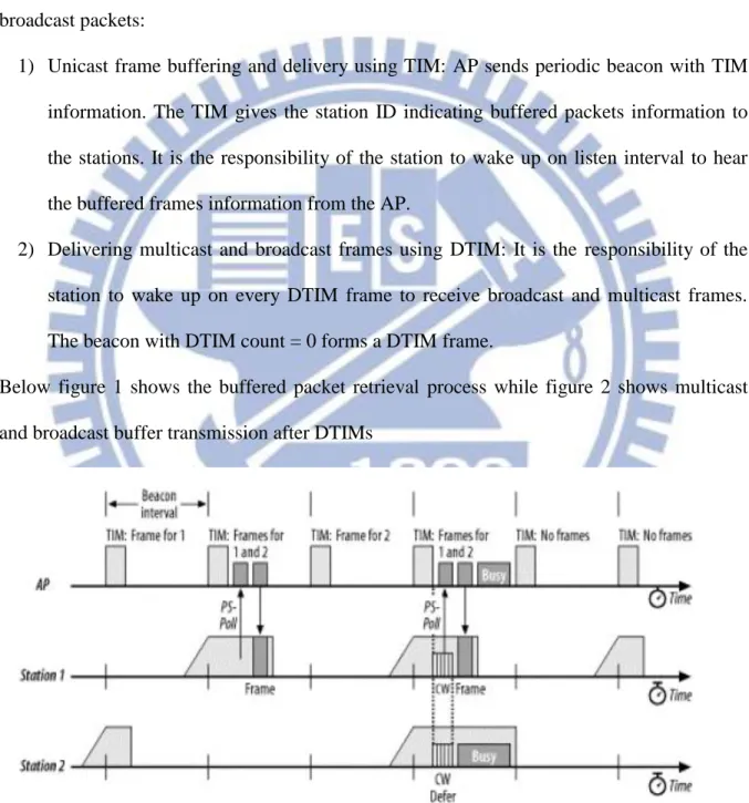
its power state from active state to doze state or visa-versa. For this purpose STA uses “power bit” in control flag of 802.11 defined PS-Poll / NULL data frame. Thus AP keeps track of each STAs state. AP buffers any incoming packets if the STA is in doze mode at that time. It then delivers those buffered packets once STA switches back to active mode of operation. AP has two different mechanisms for delivering buffered unicast, multicast and broadcast packets:
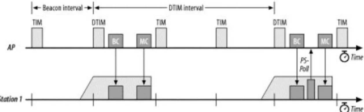
1) Unicast frame buffering and delivery using TIM: AP sends periodic beacon with TIM information. The TIM gives the station ID indicating buffered packets information to the stations. It is the responsibility of the station to wake up on listen interval to hear the buffered frames information from the AP.
2) Delivering multicast and broadcast frames using DTIM: It is the responsibility of the station to wake up on every DTIM frame to receive broadcast and multicast frames. The beacon with DTIM count = 0 forms a DTIM frame.
Below figure 1 shows the buffered packet retrieval process while figure 2 shows multicast and broadcast buffer transmission after DTIMs
9
Figure 2 IEEE 802.11 specified multicast and broadcast buffer transmission after DTIM
Several works have been done, apart from the IEEE standard 802.11 specification, to further optimize and improve power saving mechanisms in WLAN.
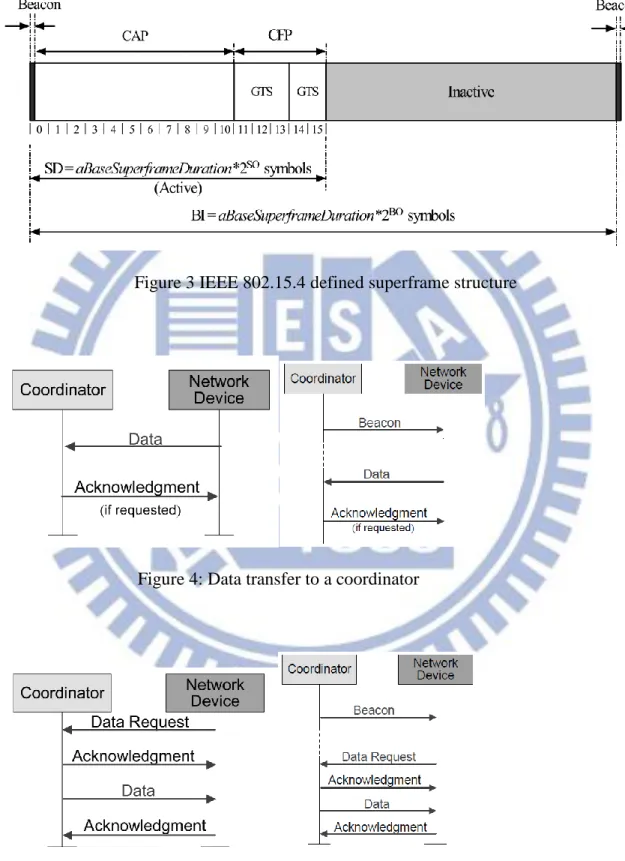
2.3 IEEE Standard 802.15.4
IEEE Standard 802.15.4 is the wireless Medium Access Control (MAC) and Physical layer (PHY) specifications for Low-rate Wireless Personal Area Networks (WPANs) [7]. It is used to convey information over relatively short distances. Unlike WLANS, connections effected via WPANs involve little or no infrastructure. This feature allows small, power-efficient, inexpensive solutions implemented for a wide range of devices included. Several M2M devices, per their application requirements, use this technology. ZigBee, specification of protocols for small, low-power radios based on IEEE 802.15.4, specifies two modes of operation: beacon-mode and non-beacon mode of operations. Unlike in the non-beacon enabled PAN, in the beacon enabled, coordinator periodically broadcast beacon so that devices know the structure of the following super-frame, and other details. A beacon-enabled PAN is used in networks that either require synchronization or support for low-latency devices. If the network does not need synchronization or support for low-latency devices, it
10
can elect not to use beacon for normal transfers. However, beacon is still required for normal discovery.
Three types of data transfer model are defined in the IEEE Std 802.15.4-2006. The first one is date transfer to a coordinator in which a device transmits the data. Second transaction is the data transfer from a coordinator in which the device receives the data. Third transaction is the data transfer between two peer devices. In start topology only two of these transactions are used because data may be exchanged only between the coordinator and a device. In a peer-to-peer topology data may be exchanged between any two devices on the network consequently all three transactions may be used in this topology. Mechanism of each transfer type depends on weather network supports beacon transmission. A beacon-enabled PAN is used in network that either requires synchronization or support for low latency devices. However, beacon is still used for discovery. Figure 4 shows data transfer to a coordinator while figure 5 shows data transfer from a coordinator.
A coordinator on a PAN can optionally bound its channel time using a superframe structure shown in figure 3 below. A superframe is bounded by transmission of a beacon frame and can have an active portion and an inactive portion. The coordinator may enter a low-power (sleep) mode during the inactivity portion.
802.15.4 defines inactive period which is the time period during which the coordinator goes to a power save mode and it would not interact with the PAN. Therefore, during this time, there will be no beacon transmissions. This implies that the devices also go to sleep mode for this duration.
IEEE standard 802.15.4 was designed since the beginning with power saving requirements in mind and thus provides a detail mechanism to enable power saving by these devices. Besides, several works have been done, apart from the IEEE standard 802.15.4 specification, to further
11
optimize and improve power saving mechanisms in ZigBee devices.
Figure 3 IEEE 802.15.4 defined superframe structure
Figure 4: Data transfer to a coordinator
12
Chapter 3: Network Architecture and Problem Statement
3.1 M2M Communication Architecture in 3GPP
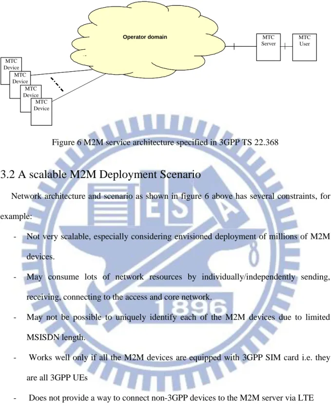
Much research and development work is ongoing to easily and efficiently integrate M2M devices with the 3GPP and other networks [8][9][10]. Integrating M2M devices with 3GPP or other networks imposes several challenges. Some of these challenges include: how to efficiently maintain connectivity of millions of M2M devices, how to minimize network overhead, how to uniquely identify each of the M2M devices, how to prevent radio network congestion in case of mass concurrent data transmission and how to enable non-3GPP M2M devices to send information to the M2M server over 3GPP network.
Figure 6 shows the current agreed M2M architecture in 3GPP. The network operator provides network connectivity to M2M server(s). An M2M server is a server, which communicates to the operator domain itself and to M2M devices through the operator domain. The M2M server also has an interface which can be accessed by the M2M User. The M2M server performs services for the M2M User. An M2M device is a UE equipped for Machine to Machine or M2M Communication, which communicates through an operator domain with M2M server(s) and/or other M2M device(s). Thus, the ongoing work is focused on scenarios where M2M devices are directly connected to the 3GPP network, i.e. assuming that these devices are 3GPP devices with M2M capabilities.
13
Figure 6 M2M service architecture specified in 3GPP TS 22.368
3.2 A scalable M2M Deployment Scenario
Network architecture and scenario as shown in figure 6 above has several constraints, for example:
- Not very scalable, especially considering envisioned deployment of millions of M2M devices.
- May consume lots of network resources by individually/independently sending, receiving, connecting to the access and core network.
- May not be possible to uniquely identify each of the M2M devices due to limited MSISDN length.
- Works well only if all the M2M devices are equipped with 3GPP SIM card i.e. they are all 3GPP UEs
- Does not provide a way to connect non-3GPP devices to the M2M server via LTE i. M2M devices (and applications) are everywhere: healthcare, smart grid, smart
metering (gas, water, electricity), sensors, RF tags, etc
ii. Majority of the above mentioned devices have non-3GPP interfaces such as
Operator domain MTC Device MTC Device MTC Device MTC Device MTC Server MTC User
14
WiFi, ZigBee, Bluetooth, and NFC.
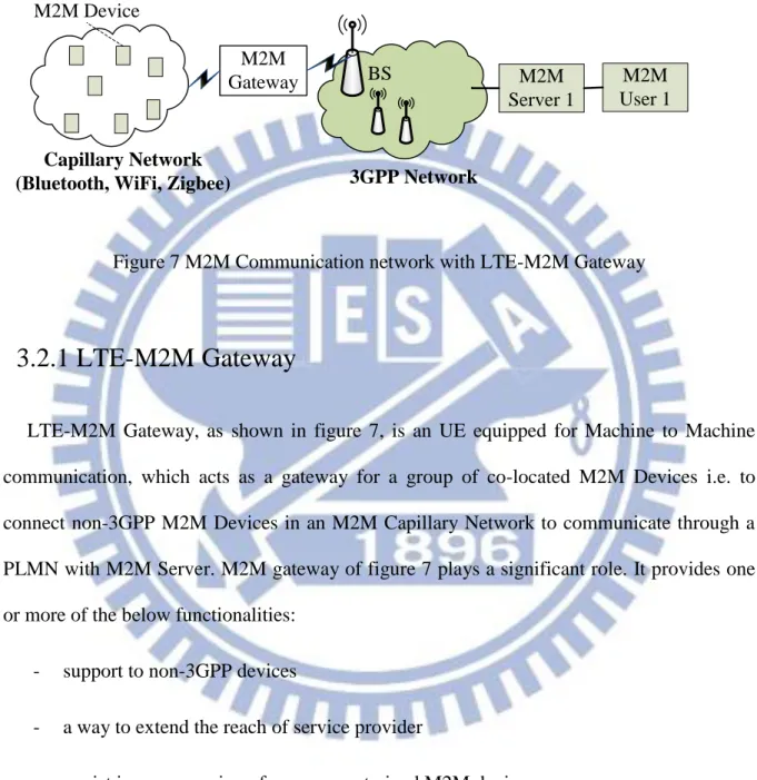
Figure 7 illustrates scalable and practical network architecture of machine-to-machine communication. The system includes one or more M2M devices forming M2M capillary network, an M2M gateway, a 3GPP LTE network, and at least one M2M server to which users are connected. Unlike in figure 6, the M2M devices of figure 7 are non-3GPP devices with interfaces such as WLAN or ZigBee.
The M2M devices forming capillary network are deployed for various applications such as disaster rescue operation, electricity, water, or gas consumption monitoring, remote health monitoring, etc. M2M devices deployed for monitoring purposes monitors events and send to the M2M server for further processing and analysis by the users. The M2M devices may be grouped as one or more groups of M2M devices based on common features, locations, etc. The M2M devices are connected to the LTE-M2M gateway through non-3GPP interface such as WLAN and Zigbee. M2M gateway is a multi-interface device with 3GPP LTE interface and non-3GPP interface and is configured to couple the M2M devices to the 3GPP network.
3GPP network includes at least one base station (BS), also known as the eNodeB. When the M2M gateway is located within a coverage area of the base station, the base station communicates with the M2M gateway. 3GPP network may also include the following components: a mobility management entity (MME) that the M2M gateway is to communicate with, a serving gateway (GW), a packet data network (PDN) GW, a policy and charging rules function (PCRF), and a home subscriber server (HSS). Each of these components is defined in the 3GPP standard specifications.
M2M server is configured to communicate with M2M devices over the 3GPP LTE network. For example, M2M server may receive monitored data from the M2M devices over
15
the 3GPP network. Also for example, the M2M server may send control, configuration or other relevant information to the M2M devices through the LTE network.
Figure 7 M2M Communication network with LTE-M2M Gateway
3.2.1 LTE-M2M Gateway
LTE-M2M Gateway, as shown in figure 7, is an UE equipped for Machine to Machine communication, which acts as a gateway for a group of co-located M2M Devices i.e. to connect non-3GPP M2M Devices in an M2M Capillary Network to communicate through a PLMN with M2M Server. M2M gateway of figure 7 plays a significant role. It provides one or more of the below functionalities:
- support to non-3GPP devices
- a way to extend the reach of service provider
- assist in power saving of power-constrained M2M devices - reduces access and core network signaling load
- possible efficient management of capillary network devices M2M
Gateway BS
Capillary Network
(Bluetooth, WiFi, Zigbee) 3GPP Network
M2M Server 1
M2M User 1 M2M Device
16
- power saving of M2M devices forming capillary network - efficient bulk transfer of data via broadcast, multicast - bandwidth aggregation
- possible gateway can assist in self-organization of M2M devices
3.3 Problem Statements
As shown in figure 7, there are two different networks involved in the communication between M2M devices and M2M server. These two networks i.e. WiFi or ZigBee capillary network and LTE network have their own power saving mechanisms and are originally designed to operate independently. For example, in case of WLAN, IEEE standard 802.11 specifies WLAN stations behavior in power save mode of operation. Similarly for LTE devices, 3GPP specifies DRX/DTX based mechanisms for power saving. Below problem statements are derived based on this fundamental observation.
3.3.1 Problem statement 1
To Synchronize WLAN and ZigBee M2M devices power saving cycles with that of M2M gateway LTE interface power save cycles while considering extended DRX cycle duration, periodic and non-periodic Tracking Area Updates (TAU). This requires design of an energy efficient network solution that enables longer doze mode and optimal mode-switch-over by WiFi or ZigBee M2M devices.
3.3.2 Problem Statement 2
17
power saving without incurring network re-entry. From the problem statement 1 above, the overall impact of maximizing idle mode duration of LTE interface is that M2M devices are able to go into sleep mode for longer duration, and reducing the periodic waking-up to check any data packet destined to itself. For this, as explained in later sections, inter-TAU duration is also used since TAU duration is often in several minutes to hours.
Chapter 4 Power Saving Solution for M2M Devices
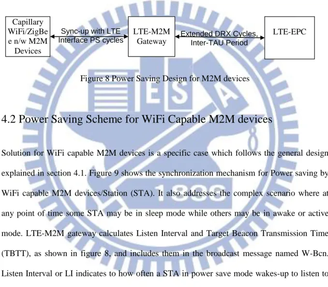
4.1 Proposed Power Saving Design for M2M Devices
Figure 8 shows proposed energy efficient network design that helps to significantly improve capillary network M2M device power saving. This lets M2M devices to enable longer doze mode and optimal mode-switch-over by synchronizing M2M devices operation modes with M2M gateway’s LTE interface power save cycle considering extended DRX cycles, periodic as well as non-periodic Tracking Area Update. Below subsections provide algorithm details for the scenario where these M2M devices support WiFi and ZigBee interfaces. In this figure, M2M gateway’s LTE interface may go to Idle mode, use DRX in connected mode, remain in active mode or may go to disconnected state. Idle mode duration may be based on extended DRX mechanism and/or inter-TAU interval, as explained in more detail in the below solutions subsections. This implies that LTE idle mode duration can range from a few milliseconds to minutes or even in hours. On the other hand WiFi Access Point (AP), for example, broadcasts periodic beacon messages usually configured to be in milliseconds. Accordingly, WiFi Stations needs to wake-up and listen to these beacon messages. However, in scenarios where LTE interface is in extended Idle mode or if there is agreement, based on message exchanges, between M2M gateway and M2M server to send
18
any downlink data only during fixed duration immediately after TAU message, the WiFi STAs need not frequently wake-up to determine if AP has any buffered data to it or not. In other words, in these scenarios, STAs need to only wake-up when LTE interface is in active mode and ready to receive or send data to/from LTE network/M2M Server and capillary network.
Figure 8 Power Saving Design for M2M devices
4.2 Power Saving Scheme for WiFi Capable M2M devices
Solution for WiFi capable M2M devices is a specific case which follows the general design explained in section 4.1. Figure 9 shows the synchronization mechanism for Power saving by WiFi capable M2M devices/Station (STA). It also addresses the complex scenario where at any point of time some STA may be in sleep mode while others may be in awake or active mode. LTE-M2M gateway calculates Listen Interval and Target Beacon Transmission Time (TBTT), as shown in figure 8, and includes them in the broadcast message named W-Bcn. Listen Interval or LI indicates to how often a STA in power save mode wakes-up to listen to beacon management frame. Beacon Interval or BI represents the number of Time Units (TUs) between Target Beacon Transmission Time (TBTT). LI is expressed in the units of Beacon Interval. One implementation option could be to keep W-Bcn as an usual standard WiFi beacon packet with “vendor specific” extension to keep the implementation simple and
LTE-M2M Gateway LTE-EPC Capillary WiFi/ZigBe e n/w M2M Devices Extended DRX Cycles, Inter-TAU Period
Sync-up with LTE
19
backward compatible. This “vendor specific” option is already available in the IEEE Standard 802.11 defined beacon packet format.
STA 2 in figure 9 is originally supposed to wake-up after every 3rd LI, however after receiving W-Bcn with new timer value, it changes its LI and thus can be in doze/sleep mode for longer duration. In case of STA 1, it is already in sleep mode when W-Bcn is sent by the gateway thus it wakes up at the usual time i.e. after LI = 5. Next time M2M gateway may send unicast packet to STA 1.
W -B cn n P-TA UW -B cn P -TA UW -B cn A P/ M TC-B ox STA 1 (LI=5) STA 2 (LI=3)
TB TT : Target B eacon Transm ission Tim e B I: B eacon Interval
LI: Listen Interval PSM : Pow er Save M ode
P-TA U : Periodic Tracking A rea U pdate (TA U ) W -B cn: B eacon w ith a vender-specific IE
n+2 n+8
P-TA U tim er length TA U TB TT A cquisition TA U TB TT A cquisition PSM Entry STA 3 (LI=2) PSM Entry PSM Entry STA 4 (LI=2)
LI Change (LI=5) & PSM Entry
LI Change (LI=4) & PSM Entry
Figure 9 WiFi power save cycle synchronization
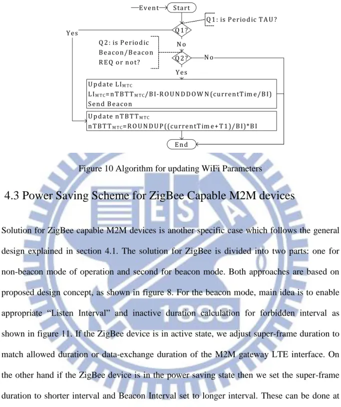
Figure 10 shows the algorithm implemented at the gateway in order to support power saving by WiFi capable M2M devices. The algorithm allows gateway to calculate Listen Interval and TBTT under different scenarios. The calculated values are then sent to M2M devices over gateway’s WiFi interface.
20 Start End Event U pdate nTB TTM TC
nTB TTM TC=R O U N D U P ((currentTim e+T1)/B I)*B I
Q 1?
U pdate LIM TC
LIM TC=nTB TTM TC/B I-R O U N D D O W N (currentTim e/B I)
Send B eacon Q 2? N o Yes N o Q 1: is Periodic TA U ? Q 2: is Periodic B eacon/B eacon R EQ or not? Yes
Figure 10 Algorithm for updating WiFi Parameters
4.3 Power Saving Scheme for ZigBee Capable M2M devices
Solution for ZigBee capable M2M devices is another specific case which follows the general design explained in section 4.1. The solution for ZigBee is divided into two parts: one for non-beacon mode of operation and second for beacon mode. Both approaches are based on proposed design concept, as shown in figure 8. For the beacon mode, main idea is to enable appropriate “Listen Interval” and inactive duration calculation for forbidden interval as shown in figure 11. If the ZigBee device is in active state, we adjust super-frame duration to match allowed duration or data-exchange duration of the M2M gateway LTE interface. On the other hand if the ZigBee device is in the power saving state then we set the super-frame duration to shorter interval and Beacon Interval set to longer interval. These can be done at the network layer. We use NLME-NETWORK-FORMATION.request and MLME-START.request as shown in figure 12.
21
Figure 11 Beacon Interval and superframe reconfiguration in Zigbee
Figure 12 Super-frame reconfiguration
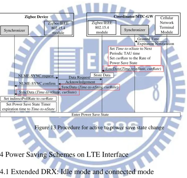
For the non-beacon mode, main ideas are to reduce periodic polling and aligning the communication window. Figure 13 shows procedures of state change of M2M devices from active state to power saving state. From implementation perspective, it starts with 3GPP module, which informs the controller unit about the inter-TAU interval or the active duration
S D = a B a se S u p e rfra m e D u ra tio n * 2S O _ A ctiv e S u p e rfra m e C o n fig u ra tio n in A c tiv e sta te
A c tiv e P e rio d A c tiv e P e rio d A c tiv e P e rio d A c tiv e P e rio d B I = a B a se S u p e rfra m e D u ra tio n * 2B O _ A ctiv e
A c tiv e
P e rio d In a c tiv e P e rio d S u p e rfra m e C o n fig u ra tio n in P S sta te
S D = a B a se S u p e rfra m e D u ra tio n * 2S O _ P S
22
during which data may be exchanged and thus it indicates allowed time or granted time interval. Controller unit in-turn triggers ZigBee module of the M2M gateway, which in turn sends appropriate notification to M2M devices in the Capillary network. Thus M2M devices learn that during this inter-TAU time, there is no data expected to arrive from network/server via the gateway device.
Figure 13 Procedure for active to power save state change
4.4 Power Saving Schemes on LTE Interface
4.4.1 Extended DRX: Idle mode and connected mode
Extended DRX solution is proposed to work between M2M Gateway’s LTE interface and LTE network. It also considers scenarios where more than one devices with LTE interface are deployed for M2M applications. These devices could be part of a group subscription and located in proximity. The proposed method is applicable in particular to UEs supporting
Synchronizer Zigbee/IEEE 802.15.4 module Zigbee Device Store Data SyncData(Time-to-nState, curRate) NLME-SYNC.request NLME-SYNC.confirm Data Request Acknowledgement
SyncData (Time-to-nState, curRate) SyncData (Time-to-nState, curState)
Set indirectPollRate to curRate
Synchronizer
Coordinator/MTC-GW
Zigbee/IEEE 802.15.4
module
Set Power Save State Timer expiration time to Time-to-nState
Enter Power Save State
Cellular Network Terminal Module Granted Time Expiration Notification Set Time-to-nState to Next
Periodic TAU time Set curRate to the Rate of Power Save State
23
applications with predictable communication cycles such as many of the existing Machine to Machine (M2M) communication. It provides system and method for enhanced DRX operation. It also provides mechanism for dynamically allocating communication-window within the allowed “Grant time-interval” to each M2M device possibly with a group deployment. The solution can be summarized as:
- Hand-shake protocol between M2M gateway and LTE core network to configure and update various DRX parameters, time-duration – requiring changes in LTE NAS protocol. Changes required by this method are kept flexible and simple to allow interoperable and standardization possibilities.
- A set of message exchanges between M2M gateway and other UEs, running M2M applications, to dynamically configure new allocated individual communication window – requiring changes in local-communication protocols i.e. WiFi or ZigBee.
The solution is designed with due consideration of the two main properties of the deployments – one, a significantly large number of M2M devices and second, ever increasing need for devices to conserve battery power. It also exploits the availability of UE with possibly group based subscription for such deployments. As shown in figure 14, the solution is divided into four steps, as explained below:
1) The network dynamically adjusts devices allowed-time Interval start time, considering inputs from HSS on the group subscription details, M2M server and total allowed duration. Allowed-time interval is when the device is allowed to send or receive data traffic, based on traffic condition, subscription-option, etc.
2) M2M Gateway interacts with LTE core network, MME, SGW in order to learn the start time as well as overall duration of newly adjusted allowed-time interval.
24
3) M2M Gateway calculates individual M2M device communication time-slot. It also calculates number of DRX long and short cycles as well as duration of each of the DRX long and DRX short cycles. The long DRX cycle can be as small as 10 ms and up to several minutes. Short DRX cycle can be as small as 2ms and as large as 640ms. These values are calculated such that the duration and number of long DRX cycle and short DRX cycles respectively are maximum possible, considering the calculated allowed time-duration.
4) Configured DRX parameters along with individual device communication time-slots are sent to each device. This can be done using non-3GPP interface protocol such as extending IEEE 802.11 or 802.15.4 MAC protocols.
Figure 14 Extended DRX
4.4.2 Inter-TAU Duration
The main point here is that downlink data transfer is only possible during an allowed time period immediately after the LTE-M2M gateway performed a TAU/RAU procedure. During that allowed time period the M2M server can communicate with the LTE-M2M gateway.
25
After the allowed time period the LTE-M2M gateway may switch off the receiver and communication is not possible. After the LTE-M2M gateway performs a TAU/RAU procedure, it may stay in power-up mode and inform the M2M Server that it is available for communication so that the M2M Server can forward all buffered traffic to the device. The M2M gateway may be configured not to inform the M2M Server after every TAU/RAU procedure and thus reduce the frequency of allowed time periods. How often an allowed time period occurs is thus configurable. For example, the M2M gateway may be configured to stay in power-up mode after a TAU/RAU and inform the M2M Server about its availability only between 1am – 5am every day. The M2M Server buffers downlink traffic for the M2M gateway until it informs the server that it is ready for M2M communications.
4.5 M2M Gateway Implementation-Design
Figure 15 shows different components of the LTE-M2M gateway. The shaded part shows enhancements of the modules required in order to improve power saving in M2M devices. As shown in the figure, M2M gateway includes non-3GPP interface such as IEEE 802.11 or WLAN, IEEE 802.15.4 or ZigBee and NFC. The figure shows non-3GPP network interface controller (NIC) module for communicating with the M2M devices, a 3GPP NIC module for communicating with the LTE network, and a core module coupled to the non-3GPP module and the 3GPP module. The non-3GPP module and M2M controller unit and 3GPP interface implements the proposed algorithm. The core module includes an M2M controller unit, which further includes a database and a controller. The controller stores information regarding the M2M devices in the database and retrieves information regarding the M2M devices from the database. The core module also includes a memory manager to manage memory usage by the database, and a communication scheduler to schedule communications
26
between the M2M gateway and the M2M devices and communications between the M2M gateway and the 3GPP network.
The 3GPP LTE module includes, apart from a standard LTE protocol stack, an M2M enable unit which implements hand-shake protocol to enable extended DRX cycle as discussed in the previous section. Also, for example, the M2M enable unit may send, periodically or non-periodically, updated information regarding the M2M devices to the LTE network using Tracking Area Update messages. This is used to update MME database of the LTE network with the initial or updated information regarding the M2M devices which can then be used to monitor and control these devices via M2M gateway.
27
Chapter 5 Modeling
5.1 Simulation Environment
We used OPNET Modeler simulator [12]. Figure 16 and figure 20 shows network topologies we implemented in OPNET simulation environment for analyzing our power saving solutions. In this topology, an M2M server is connected to the LTE network. An LTE UE with an additional Ethernet interface is connected to a WiFi AP and represents M2M gateway, when considered along with other required functionalities. The M2M device equipped with WiFi interface communicates with the M2M server through the WiFi AP. During each simulation run, the M2M user sends or requests data to or from the M2M server which in turn communicates with M2M devices. The M2M gateway, which implements proposed functionalities, buffers and queues any requests in case the M2M device is in sleep state. After wake-up, M2M device initiates PS-Poll mechanism, in case WiFi AP indicates any buffered data for it using TIM bit in the beacon message. After retrieving all the buffered packets, it may decide to go back to sleep mode again.
28
5.2 Simulation Results and Analysis
5.2.1 Extended DRX in Connected mode
For the extended DRX power saving evaluation, simulation parameters and their values are listed in below table 1 and table 2. We used different traffic models for evaluation. In figure 17, small data packets of fixed size (100 bytes) arriving at constant intervals of 30 seconds (blue graph) and 30 minutes (purple graph) are considered. While in figure 18, exponential-interval traffic with mean arrival time of 30 seconds (blue graph), 5 minutes (yellow graph) and 30 minutes (purple graph) are considered. For simplicity, we disabled the short DRX cycle, and only adopt the long DRX cycle. For the configured values, as shown in Table 1 and Table 2, in Normal state UE’s transmitter and receiver are ON, in Active state UE’s receiver is ON and it can receive paging messages on PDCCH, and in sleep state UE’s transmitter and receiver are Off.
Table 1: Attributes for Extended DRX simulation Operating Power in Normal State (mW) 100 mW
Operating Power in Active State (mW) 40 mW Operating Power in Sleep State (mW) 10 mW
Table 2: Attributes for connected mode Simulation On Duration Timer (Subframes) 50
Short DRX Cycle Timer (Subframes) 160
Use Short DRX Cycle Disabled
Inactivity Timer (Subframes) 100 Retransmission Timer (Subframes) 4 Long DRX Cycle Multiplication Factor 1
29 0 5 10 15 20 25 30 35 0 10000 20000 30000 40000 50000 DRX Cycle Timer (Subframes)
P ow er C ons um pt ion / H our ( m W h) Pkt inter-arrival tim e 30s Pkt Inter-arrival tim e 30 m in
Figure 17 UE power consumptions with different DRX cycles and traffic condition
0 5 10 15 20 25 30 35 0 10000 20000 30000 40000 50000
DRX Cycle Timer (Subframes)
Pow er C onsum pt ion / H our ( m Wh)
Figure 18 UE power consumptions with different DRX cycles and traffic condition
From the simulation results shown in figure 17 and figure 18 we observe that by increasing DRX cycle duration from 0.08 seconds to 40 seconds, power consumption is reduced by about 60% reduction. It is noted that 3GPP specification TS 36.331 [16], recommends longDRX minimum value of 0.01 seconds and maximum of 2.56 seconds. Also, it
30
recommends shortDRX minimum value of 0.002 seconds and maximum of 0.64 seconds. However, this specification is for usual UE devices and is not optimized for M2M devices. These values are recommended considering various factors such as signalling overhead, delay, applications, user requirements and lack of reliable ways to predict traffic patterns. Considering the power saving advantages in M2M devices by increasing DRX cycles, 3GPP as part of Release-12, is currently discussing different approaches and may specify one or more solutions sometimes by early 2014.
5.2.2 Extended DRX in Idle mode
Figure 19 shows power consumption with respect to different DRX cycle and traffic conditions. The curve with the blue line considers small data packets of fixed size (100 bytes) arriving at constant intervals of 30 seconds. While in case of pink curve packets inter-arrival time is 300 seconds. Table 1 and Table 3 show various configured values for the purposes of Idle mode simulation results.
Table 3 Attributes for Idle Mode Simulation On Duration Timers (Subframes) 50
Short DRX Cycle Timer (Subframes) 64
Use Short DRX Cycle Disabled
Inactivity Timer (Subframes) 100 Retransmission Timers (Subframes) 4 Long DRX Cycle Multiplication Factor 1
31
0
5
10
15
20
25
30
0 20000 40000 60000 80000 100000DRX Cycle Timer (Subframes)
T otal Powe r Cons umpti on ( mWh)
Figure 19 UE power consumptions with different DRX cycles and traffic condition
5.2.3 Capillary network M2M Device Power saving
As shown in figure 20, we create a simulation environment using the OPNET simulator in which an M2M server was connected to the LTE network and an UE with an additional Ethernet interface was connected to a WiFi AP. The M2M device which is equipped with WiFi interface communicates with the M2M server through the WiFi AP. Note that the UE and the WiFi AP are collectively treated as an M2M gateway. During a simulation run, the M2M user requests data from the M2M server which then conducts small data transmission with the M2M device. The M2M gateway enabling the proposed method queues requests until the M2M device wakes up at the beginning of next power save cycle. While waking up, the M2M device deals with all the requests queued in the M2M gateway and goes back to idle mode afterwards. The simulation time was set to 3 days in each simulation run. Among the simulation runs, some mandatory parameters were varied. The simulation environment settings & parameters are listed in Table 4, where values of SDT request rates mean that the SDT request inter-arrival times are exponentially distributed (i.e., a Poison process) with mean
32
value 30 seconds.
Figure 20 Network Topology for Simulate Purposes
Figure 21 shows the cumulative power consumption over time with different small data transmission request rates. The M2M device operating in a traditional power saving scheme was set listen interval to 10, 110, and 300, respectively, and denoted as “WiFi PS.” We observe that the M2M device with a large listen interval wakes up less frequently, saving more power than those with smaller intervals. On the other hand, the M2M device with the proposed method, which is denoted as “M2M PS”, does not wake up during Idle intervals, consuming less power than WiFi PS.
33
d = 3 Hrs d = 9 Hrs
Figure 21 Total Allowed Time Required vs. number of M2M Devices
Table 4: Parameters for WiFi Simulation Scenario
Parameter (Notation) Value(s)
WiFi AP Beacon Interval (dBI) 0.5 seconds
Periodical TAU Interval (power save cycle) (d) 10800, 32400 seconds WiFi STA (M2M device) Listen Interval (LI) 10, 110, 300 BIs Small Data Transmission (SDT) Request Rate (r)
exponential(30) seconds Tx Power Consumption at MTC Device (eTx) 330 mA
Rx Power Consumption at MTC Device (eRx) 280 mA
Active Mode Power Consumption at MTC Device (eA) 178 mA
Idle Mode Power Consumption at MTC Device (eI) 9 mA
34
Chapter 6: Conclusion and Future Work
Motivated by the tremendous opportunities along with several technical challenges imposed by Machine to Machine Communication, we selected this as our topic of research. After investigating several M2M related technical issues and observing that power saving is a very significant constraint in these, often small and wireless M2M devices, we decided to take this challenge of designing a novel and innovative solution which would eventually reduce power consumption and hence increase overall battery life of these M2M devices. We went through several M2M applications & communication scenarios and figured out that in order to truly live-up to expectation of numerous envisioned M2M deployments, M2M gateway would be an important component of the architecture. We studied details of such hybrid and scalable architecture. This architecture consists of 3GPP LTE network on one side while a non-3GPP network, e.g. of WiFi or Zigbee devices, on the other side of the M2M gateway.
We came-up with power saving solution design for the hybrid M2M network. Based on this approach, we designed detail solutions to enable low power consumption by M2M devices with IEEE standard 802.11 or IEEE standard 802.15.4 network interface. The low power consumption by M2M devices is supported by algorithm and hand-shake protocols implemented at the LTE-M2M gateway.
OPNET modeler was used for simulating the proposed network design and solutions for the purposes of evaluation and analysis. Multiple simulations were performed and the results were recorded, both on the M2M gateway and on the M2M devices. Simulation results were very encouraging and shows power saving improvements. These improvements came from the proposed IEEE 802.11 based solution as well as extended DRX based solution.
35
to simulation, the real-world environment will show accurate benefits and encourage practical feasibility. Besides, the proposed solution design can also be extended to any other existing or future M2M communication technologies, thus not limited only to WiFi or Zigbee enabled M2M devices.
Bibliographies
[1] 3GPP, http://www.3gpp.org [2] ETSI TC M2M www.etsi.org
[3] C. Kim, et al., "Global Wireless Machine-to-Machine Standardization," Internet Computing, IEEE, vol. 15, pp. 64-69, 2011.
[4] L. Shao-Yu, et al., "Toward ubiquitous massive accesses in 3GPP machine-to-machine communications," Communications Magazine, IEEE, vol. 49, pp. 66-74, 2011.
[5] W. Guo, et al., "An adaptive medium access control mechanism for cellular based Machine to Machine (M2M) communication," in Wireless Information Technology and Systems (ICWITS), 2010 IEEE International Conference on, 2010, pp. 1-4.
[6] 3GPP TS 36.321 V11.2.0 (2013-03): “Evolved Universal Terrestrial Radio Access (E-UTRA); Medium Access Control (MAC) protocol specification
[7] IEEE Standard 802.15.4-2006: wireless Medium Access Control (MAC) and Physical layer (PHY) specifications for Low-rate Wireless Personal Area Networks (WPANs) [8] L. Shao-Yu, et al., "Toward ubiquitous massive accesses in 3GPP machine-to-machine
communications," Communications Magazine, IEEE, vol. 49, pp. 66-74, 2011.
36
Technology Conference Fall (VTC 2010-Fall), 2010 IEEE 72nd, 2010, pp. 1-4.
[10] W. Guo, et al., "An adaptive medium access control mechanism for cellular based Machine to Machine (M2M) communication," in Wireless Information Technology and Systems (ICWITS), 2010 IEEE International Conference on, 2010, pp. 1-4.
[11] 3GPP TS 22.368: Technical Specification Group Services and System Aspects: Service requirements for Machine-Type Communications (MTC)
[12] OPNET Simulator http://www.opnet.com/
[13] Shubhranshu Singh, K. L. Huang, Bao-Shuh Paul Lin, ” An Energy-Efficient Scheme for WiFi-capable M2M Devices in Hybrid LTE Network” IEEE International Conference on Advanced Networks and Telecommunications Systems, 2011, Bangalore, India
[14] Shubhranshu Singh, K. L. Huang, ”A Robust M2M Gateway for Effective Integration of Capillary and 3GPP Networks”, IEEE ANTS, 2012, Bangalore, India
[15] IEEE Standard 802.11-2007: Wireless LAN Medium Access Control (MAC) and Physical layer (PHY) specifications
[16] 3GPP TS 36.331: Technical Specification Group Radio Access Network Evolved Universal Terrestrial Radio Access (E-UTRA)Radio Resource Control (RRC);Protocol specification