國立交通大學
電機資訊國際學程
碩士論文
以雲端和 Android 為架構的⼾戶外盲⼈人導路系統之實作
Prototype of Cloud and Android Based Outdoor Guidance System for the
Visually Impaired
學⽣生:賴安娜
指導教授: 林寶樹
Prototype of Cloud and Android Based Outdoor Guidance System for the
Visually Impaired
學⽣生:賴安娜
Student: Anna Lapyko
指導教授: 林寶樹
Advisor: Dr. Bao-‐Shuh Paul Lin
國⽴立交通⼤大學
電機資訊國際學位學程
碩⼠士論⽂文
A Thesis
Submitted to EECS International Graduate Program
National Chiao Tung University
in Partial Fulfillment of the Requirements
for the Degree of
Master
July, 2013
Hsinchu, Taiwan, Republic of China
以雲端和 Android 為架構的⼾戶外盲⼈人導路系統之實作
學生: 賴安娜 指導教授: 林寶樹
摘要:
對於盲人或視障者(Blind and Visual Impaired Person, BVI)能安全地在不熟悉的戶外環境
行走,是一種挑戰,這一篇論文,介紹一個實作的雛型系統 COANS (Cloud-‐based Outdoor
Assistive Navigation System),它是利用雲端運算來協助 BVI 在戶外且不熟悉的環境,使他們
承受比較少的壓力。這個系統在使用者端的硬體設備是一支 Android 的智慧型手機,和一
部低價外掛的 L1 GPS 接收機,它用來加強位置的精確度,所應用的方法叫 RTK (Real-‐time
Kinematic)來使得使用者所在的位置更準確。在智慧型手機的應用程式和使用者之間的互 動是以聲控(voice control)和聲告(voice notification),搭配抖動(shaking)和磨擦(swiping), 達到親和的人機介面,這個測試情境是一套系統,亦涵蓋了偵測交通號誌的狀態,斑馬線的偵 測,以及在BVI 附近所偵測到的板凳。
關鍵詞: RTK, 輔助技術, 雲端科技, ⾏行動通訊, 導航, 視覺障礙
Prototype of Cloud and Android Based Outdoor Guidance System for the Visually
Impaired
Student: Anna Lapyko Advisor: Dr. Bao-‐Shuh Paul Lin
Abstract
Safe navigation in non-‐familiar outdoor environments is a challenging activity for the blind and vision-‐impaired (BVI) people. This work introduces a prototype of a cloud-‐based outdoor assistive navigation system (COANS) for BVI people. The main goal of the system is to provide easy street navigation and help to make outdoor walks in non-‐familiar environment less stressful. Hardware part from the user-‐side includes an android-‐base mobile phone and an external low-‐cost L1 GPS receiver to improve position accuracy. Applying the technique known as Real Time Kinematic (RTK) ameliorates the issue of the user position estimation. Interaction between the application and the user is based on voice commands (user-‐side) and voice notifications (system-‐side), together with the user-‐ friendly “shaking” and “swiping” commands. The test scenarios for the system include traffic light status detection, zebra crossing path detection and a bench discovering within a short distance from the user.
Keywords: assistive technology, cloud, mobile, navigation, visually impaired, RTK
Table Of Contents
Table of Figures ... iv
List of Tables ... v
List of Acronyms ... vi
I. Introduction ... 1
1.1 Motivation ... 1
1.2 Purpose and Objectives ... 2
1.3 Problem statement ... 2
1.4 Thesis outline ... 3
II. Related Work Discussion ... 4
III. Background ... 8
3.1 GPS location positioning background ... 8
3.1.1 GPS signals and types of GPS receivers ... 10
3.1.2 GPS accuracy Improvement background and related works ... 11
3.1.3 Main differences between NMEA format and raw/binary data (UBX protocol) ... 12
3.1.4 RTKLib ... 15
3.2 Android Application background ... 16
3.2.1. Android Platform ... 16
3.2.2 Android programming languages and developer tools ... 17
3.2.3 Access smartphone sensors with Android ... 17
3.2.4 Android Application Components ... 18
3.2.5 Google Cloud Messaging Service ... 18
3.3 Geospatial Analysis Background ... 18
3.3.1 Calculating distance between two given points ... 19
3.3.2 Calculate bearing between two given points ... 24
3.3.3 GIS (geographic information systems) software and maps used in the project ... 26
IV. Navigation System Requirements ... 28
4.1 Functional Requirements ... 28
4.1.1 User Case Scenarios ... 28
4.1.2 Android Application Requirements ... 30
4.1.3 Server-‐side framework requirements ... 30
4.1.4 Server-‐Side implementation for External GPS binary data processing ... 31
4.2 Hardware Requirements ... 31
System User-‐side Hardware Requirements ... 31
V. Proposed System Architecture and Implementation ... 34
5.1 External GPS receiver and RTKLib server ... 34
5.2 RTKLib server and RTK Reference Station Connection ... 36
5.3 RTKLib server – Android Phone Connection. Coordinates delivery to android phone. ... 36
5.4 Cloud-‐server and android phone messaging delivery mechanism ... 38
5.5 Android phone and cloud server communication ... 38
5.6 Android Application Implementation ... 42
VI. Testing Performance Results ... 45
VII. Final Remarks ... 54
References ... 56
Table of Figures
Figure 1 -‐ Studies [2] proposed system architecture ... 5
Figure 2 -‐ Skyhook location accuracy ... 7
Figure 3 -‐ Errors on GPS Signal [41] ... 8
Figure 4 -‐ Multipath effect ... 9
Figure 5 -‐ GPS signals ... 10
Figure 6 -‐ NMEA 0183 format [38] ... 13
Figure 7 -‐ Android Architecture [33] ... 17
Figure 8 – Bearing between NCTU and NTHU given points ... 25
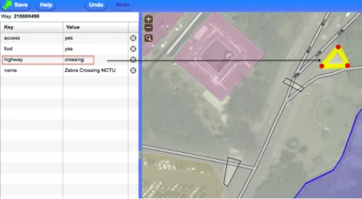
Figure 9 – OSM, add polygon ... 26
Figure 10 – QGIS, OpenStreetMap vector layer ... 27
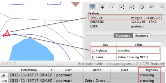
Figure 11 -‐ Zebra Crossing Case scenario ... 28
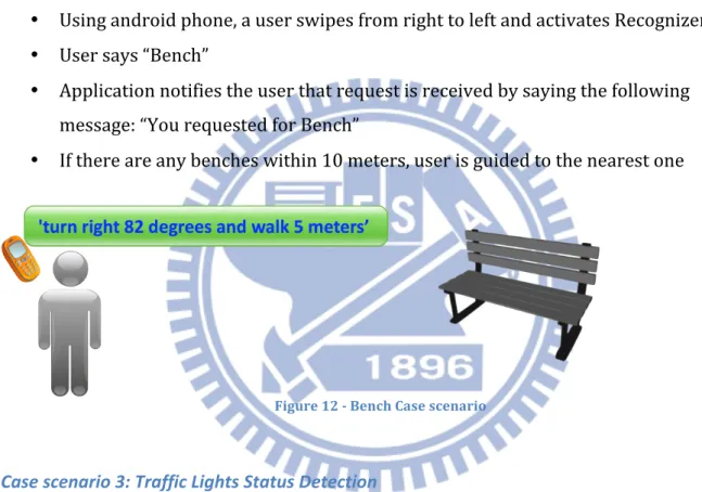
Figure 12 -‐ Bench Case scenario ... 29
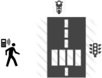
Figure 13 -‐ Traffic Light Detection Case scenario ... 30
Figure 14 – GPS Receiver Boards/Modules Supporting Raw Measurement and Satellite Ephemeris Output [22] ... 32
Figure 15 -‐ Neo FreeRunner ... 32
Figure 16 – NEO Freerunner Component Side ... 33
Figure 17 -‐ External GPS to RTKLib Direct Connection: serial/usb cable ... 34
Figure 18 -‐ External GPS to RTKLib Wireless Connection ... 34
Figure 19 -‐ UBX data transfer, IO statistics ... 35
Figure 20 -‐ RTK-‐GPS/GNSS with NRTK service via Internet [source: rtklib documentation] ... 36
Figure 21 -‐ Proposed Architecture, location coordinates delivery to android phone ... 37
Figure 22 – Google Cloud Messaging Delivery mechanism ... 38
Figure 23 – Client and Server initialization Logic ... 40
Figure 24 – User-‐side and server-‐side logic overview ... 42
Figure 25 – Android Application Installation Process ... 43
Figure 26 – Application Info Window ... 43
Figure 27 – Android Application Main Window ... 44
Figure 28 – Android Application Speech Recognition Interface ... 44
Figure 29 – Android Application Shake Recognition Mechanism ... 45
Figure 30 – NEO Freerunner, Low-‐Cost GPS antenna ... 46
Figure 31 – RTKLib Single Mode Results ... 47
Figure 32 – RTKLib Single Mode vs PPP static mode results ... 48
Figure 33 – RTKLib RTK mode, “FIX” solution results ... 49
Figure 34 – RTKLib RTK mode, “FLOAT” solution results ... 49
Figure 35 – Testing Environment (Network) ... 50
Figure 36 – GCM response time, LTE ... 51
Figure 37 – Traffic Light Status Delivery Time, LTE ... 52
Figure 38 – Battery efficiency test, first stage ... 53
Figure 39 – Battery efficiency test, second stage ... 53
List of Tables
Table 1 -‐ GPS Error Budget ... 9
Table 2 -‐ NMEA $GPRMC sentence information ... 13
Table 3 -‐ Android Application Components ... 18
Table 4 -‐ Server-‐side NoSQL databases and stored information ... 39
Table 5 -‐ Comparison of [2] system and proposed in this thesis system ... 54
List of Acronyms
A-‐GPS Assisted GPS
AWS Amazon Web Services
BVI The Blind and Vision Impaired C/A Coarse Acquisition (Code)
DGPS Differential Global Positioning System
EGNOS Euro Geostationary Navigation Overlay Service GCD Great Circle Distance
GCM Google Cloud Messaging
GIS A Geographic Information System GNSS Global Navigation Satellite System GPS The Global Positioning System IaaS Infrastructure as a Service LTE Long Term Evolution
MBR Minimum bounding rectangle
MSAS Multi-‐Functional Satellite Augmentation System NMEA National Marine Electronics Association
NTRIP Networked Transport of RTCM via Internet Protocol PaaS Platform as a Service
POI Point Of Interest
QGIS Quantum GIS (Open Source Geographic Information System) RTCM The Radio Technical Commission for Maritime Services RTK-‐GPS Real-‐Time Kinematic GPS
SA Selective Availability SaaS Software as a Service
SBAS Satellite Based Augmentation Systems TTFF Time-‐To-‐First-‐Fix
TTS Text-‐To-‐Speech UI User Interface
WAAS The Wide Area Augmentation System
WiMAX Worldwide Interoperability for Microwave Access WGS84 World Geodesic System -‐ revision dating from 1984
I. Introduction
1.1 Motivation
For the past decades communication technologies have been rapidly developed. High bandwidth and low latency wireless networks are widely used around the world, bringing additional benefits in people’s every-‐day life and assisting in making it more mobile and flexible.
Services, based on brand new communication technologies, are becoming an important functional part of the modern society. Every day more and more people rely on such services to make their phone calls, participate in videoconferences while travelling in a high-‐speed train, securely backup sensitive data, use location services in unknown environment both for business and pleasure, etc. In other words, mobility brings a new level of freedom and enriches the quality of the everyday life.
Additionally, as a result of a huge and continuously growing market of handheld appliances, the mobile devices are getting easier to get and afford.
Thank to prerequisites mentioned above, communication services are nowadays in a huge demand not only in business sector and end-‐user applications, but also in a health care environment.
Turning to the health care field, needless to say that in the recent years plenty successful projects have been completed in order to help visually impaired and blind people to use modern communication techniques equally with the sighted people. These include web browsing, emailing (both sending and receiving), and many more.
In spite of the mentioned above, it would be fair to notice that still in the most of the cases visually impaired and blind people are limited in mobility. Therefore, development of special infrastructures can not only enrich mobility of visually impaired people, but also bring additional sense of security to their lives. As mentioned in [2], “visually impaired or blind persons rely on their previous knowledge of an environment to navigate, usually getting help from guide dogs or white canes. This leaves them handicapped in achieving the desired level of mobility and context-‐awareness especially in unknown environments”.
Above all, even with traditionally accepted guidance assistants like dogs and white canes, blind people still face limitations in their usage. As fairly noticed in [7], “as societies are developed and the structure of cities is complicated, the use of both things1 became limited
and restricted”.
Taking everything mentioned above into consideration, development of an infrastructure based on modern technologies could help to achieve a higher level of mobility and at the same time increase general safety of the visually impaired and blind people.
1.2 Purpose and Objectives
The purpose of this work is to propose a scenario for adopting new communication technologies together with using affordable mobile devices in order to provide assistive guidance service for visually impaired and blind people.
Based on the motivations mentioned above, the objectives for this Master thesis are the following:
• to review essential parts of related works;
• to identify the techniques that could be combined for an efficient and user-‐friendly mobile application for visually impaired/blind people;
• to specify a cloud-‐based framework for a blind navigation system 1.3 Problem statement
Although existing navigation systems partially guarantee real-‐time delivery and accuracy in traffic lights status detection, the problem of traffic lights status change prediction has not been addressed and solved. It is important to notice that prediction of traffic lights status change is an important component in an effective and safe guidance system.
When referring to system usability, there are two main types of navigation architectures for blind people: so-‐called “wearable” systems and “mobile” systems. Wearable systems consist of several hardware components combined together and are supposed to be put on a guided person. The main disadvantage in usability of these systems is that they are usually quite heavy (around 4kg). Although utilizing several hardware components allows to achieve a better accuracy and expand opportunities for useful case scenarios, these systems are not easy to wear and they may be not accepted by people for every day
navigation. On the other hand, mobile types of navigation systems require only one device on a user-‐side, which guarantees a greater flexibility to a guided person. However, because of powerful hardware limitations, these systems not always can achieve same performance rate as the wearable systems. The system architecture proposed in this Master thesis addresses this issue and is aimed to find a compromise between overall system usability and system performance.
1.4 Thesis outline
The structure of this thesis is based on the determined objectives and is divided into 7 chapters.
• Chapter 1 gives the introduction to an overall view of this study; formulates purpose and objectives of this study.
• Chapter 2 focuses on theoretical background of the research and provides a literature review of the studies related to navigation systems for visually impaired/blind people.
• Chapter 3 provides detailed information about project related background, such as GPS positioning introduction, RTKLib introduction. This chapter also explains the difference between NMEA protocol and the binary protocols (like UBX). The last part of the Chapter 3 discusses Android related background together with GIS formulas and related libraries/software that are used in the proposed architecture. • Chapter 4 describes the main requirements to the navigation system. It includes so-‐ called functional requirements and provides user case scenarios. Additionally this chapter mentions client-‐side hardware requirements.
• Chapter 5 provides information about the system architecture and implementation. It also provides information about testing results.
• Chapter 6 gives description of testing environment and summarizes testing performance results.
• Chapter 7 summarizes the important information about the project. It includes conclusions part and future works part.
II. Related Work Discussion
Several interesting research have been already done in this field; and both outdoor and indoor navigation systems for visually impaired and blind people been proposed. These systems are based on different approaches and technologies in order to provide functional variety and be useful to navigate in both known and unknown environment.
Proposed architectures include both so-‐called “wearable navigation systems” [19, 13, 21, 36] together with more mobile solutions when only one assisted portable device is required on the users side. Such portable devices might include a mobile unit [15], a smartphone [10, 2, 11], or even improved high-‐tech version of White cane [7, 39].
In [13] authors discuss necessity of building a navigation system that covers both indoor and outdoor case scenarios. They provide a description of “an integrated framework of a precise navigation system for visually impaired and blind people” [13]. Although some interesting ideas were proposed in this work, there is still a necessity for tests results, including performance and usability.
Studies [19] also propose outdoor and indoor wearable navigation system for visually impaired and blind people. For outdoor location positioning DGPS technique is used and special hardware equipment (Trimble PROXRS, 12 channel integrated GPS/Beacon/Satellite receiver with multi-‐path rejection technology) is introduced in the system in order to improve users outside location.
Koley et al. [21] introduces a navigation system for visually impaired persons, that combines usage of GPS, voice and ultrasonic sensor for obstacle detection. In the proposed system SiRFstarIII GR-‐301 GPS Receiver is used for outdoor location positioning. No GPS accuracy improvement techniques (RTK, DGPS, etc.) are used in order to improve outdoor location accuracy.
There are several systems designed particularly for traffic lights detection in order to help both color-‐blind drivers and visually impaired pedestrians [28, 29]. These systems are based on image recognition and video processing technologies.
As the purpose of this work is to provide an easy guidance assistance infrastructure that involves android-‐based mobile handheld device, the most relative works to this one also includes a mobile device and its equipped technologies like GPS and Networking modules.
One of the most relevant to this work research is [2]. The authors proposed cloud-‐based system architecture used together with an android-‐based mobile phone in order to detect traffic light status. This approach is based on video analysis techniques and requires a user to use GPS, Networking and Camera functionality on the mobile phone.
Proposed in [2] infrastructure includes two main components – a mobile device and a cloud server component. A mobile device computes its location using GPS satellites information and updates the cloud server with the current user location. It also serves as a video recording tool to capture traffic lights status. Cloud server component is responsible for processing the information received from the mobile device and sending back a response.
Studies [2] proposed architecture is shown in the Figure 1.
Although this work introduces interesting architecture, there are obviously several weaknesses that make it less efficient in comparison with so-‐called communication-‐based model2, introduced in this work.
In our opinion, video analysis or image processing based models would always introduce several important drawbacks, affecting the whole system usability and more importantly compromising the safety of a visually impaired/blind person.
One the biggest concern regarding the proposed architecture is an unhandled safety issue when a visually impaired or blind person is supposed to cross a road. Although, the authors discuss the importance of fast and reliable traffic light detection capability and mention real-‐time video frames processing, still the system lacks of actual real-‐time traffic light information status. Let us imagine the following case scenario: a traffic light is still in “Green” state, but it is going to change its status to “Red” in 3 seconds. A mobile phone user captures traffic light (“Green”) and sends frame for analysis to the cloud. Obviously that even if the frame is analyzed immediately, and a person gets instruction to cross the road, there is still not enough time for them to comfortable and safely cross the road. This unavailability to predict traffic light status changes might introduce a great safety problem and compromise the whole system.
Another concern regarding proposed architecture is certain inconvenience for visually impaired/blind people to use the system. A requirement to record video along the path may lead to a big number of so-‐called “false records” when a user is not able not make camera adjustments manually. Particularly this may affect an ability to use camera in unknown environments, when exact traffic light locations and positions (including their height) are not obvious. Because of this uncertainty of traffic light locations, the architecture requires an introduction of additional assistance technology in order to easily adjust camera for successful video recording.
One more specific characteristic of the proposed in [2] architecture is related to outdoor location accuracy. As depicted in Figure 1, Skyhook Wireless positioning system is integrated in [2] architecture. Skyhook is a software-‐only location system that combines
2 The name of so-‐called communication-‐based model refers to the idea to make traffic lights status information available
online
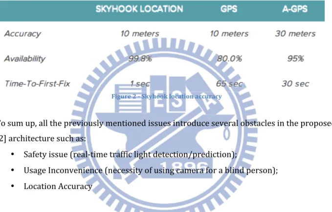
Wi-‐Fi positioning together with GPS and cell tower triangulation, its location's hybrid positioning accuracy is compared to both GPS and A-‐GPS in Figure 2.
Although, Skyhook provided services are flexible and fast, their location accuracy is never better than GPS. For some applications the fastest Time-‐to-‐Fix and constant availability is the most important characteristics in location services. These characteristics are also very important for blind navigation system, however better accuracy in location positioning detection is in the greatest demand.
Figure 2 -‐ Skyhook location accuracy
To sum up, all the previously mentioned issues introduce several obstacles in the proposed [2] architecture such as:
• Safety issue (real-‐time traffic light detection/prediction);
• Usage Inconvenience (necessity of using camera for a blind person); • Location Accuracy
Therefore, the navigation system proposed in this Master thesis, is aimed to improve these weaknesses together with introducing new user case scenarios for outdoor navigation.
III. Background
3.1 GPS location positioning background
GPS location solutions are computed by means of pseudo-‐range positioning. A GNSS receiver measures the ranges of minimum 4 visible satellites and their positions when their positions. In order to compute pseudo-‐ranges of each satellite, a GNSS receiver multiplies the time taken for each signal to reach the receiver by the speed of light:
pseudorange (distance) = (time difference) x (speed of light) (1)
Pseudo-‐range has prefix “pseudo-‐”, because of the inevitable clock errors. The reason for that is because “receivers are generally equipped with quartz crystal clocks that do not necessarily keep the same time as the more stable satellite clocks” [30].
Satellites clock error is only one type of errors that affects the accuracy of GNSS receiver positioning solution. The other errors that must be taken into consideration are orbit errors, ionospheric delays, tropospheric delays and multipath. These are main typical types of errors that are mentioned in the most textbooks.
Picture below illustrates the main types of errors that affect quality of GPS signals:
Figure 3 -‐ Errors on GPS Signal [41]
The approximate error budget is summarized in Table 1 below:
Table 1 -‐ GPS Error Budget
Type of Error Approximate Error Range
Satellite Clocks ~2 m
Orbit Errors ~2.5 m
Ionospheric Delays ~5 m
Tropospheric Delays ~0.5 m
Multipath ~1 m
As can be seen from the table, ionospheric delays are the most significant source of error for GPS positioning, followed by orbit errors. Multipath is a common for urban environment source of error and can affect total GPS accuracy for at least of 1 meter. Total summary error range in bad weather conditions could reach up to 15 meters.
Ionospheric delays are the delays in signals propagation. Satellites signals travel with the velocity of light, however their speed of propagation in the troposphere and ionosphere is slower.
Satellite Orbits shifts can influence GPS receiver positioning solution accuracy. These shifts may occur because of the gravitation forces and solar pressure fluctuations. Satellite Orbits changes are being constantly monitored by the US Department of Defense; and if any variance between predicted and actual orbits are detected, the corrected information is sent back to the satellites. Satellites then broadcast information about orbital position errors, which is called ephemeris.
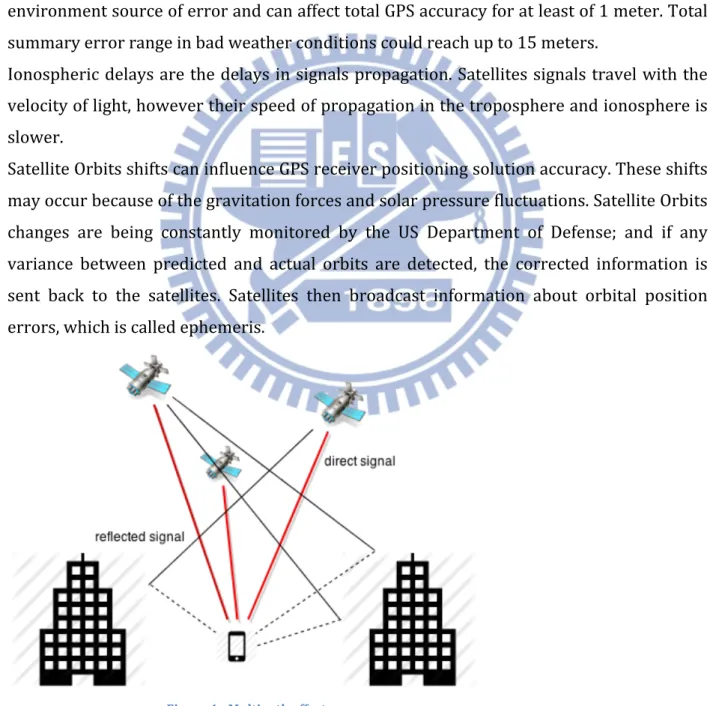
Figure 4 -‐ Multipath effect
The multipath effect is caused when satellite signals are reflected on objects. For example, in urban areas the large buildings or other large objects/constructions, power lines, trees and vehicles mostly reflect satellites signals. In rural environments lakes and trees could reflect satellites signals. Because of this kind of reflection, the signals need more time in order to reach the receiver comparing to the direct, non-‐reflected signal. This delay in the travel path leads to errors in position calculations. Figure 4 illustrates multipath effect in an urban area.
3.1.1 GPS signals and types of GPS receivers
GPS signal -‐ is a radio wave that is being constantly transmitted from GPS satellites. There two frequencies used to transmit GPS signals:
• L1 (1575.42 MHz) and • L2 (1227.60 MHz)
The difference between these two signals is that L1 frequency includes the civilian Coarse Acquisition (C/A) Code together with military Precise (P) Code; and L2 frequency only contains the P code. To prevent anti-‐spoofing attacks this P code is encrypted by the military. In order to calculate positions, all the civilian type GNSS receivers use the C/A Code on the L1 frequency. However, more expensive and precise survey grade civilian receivers operate with both L1 and L2 frequencies.
Figure 5 -‐ GPS signals
Additionally, P (Y) encrypted Code is used on both L1 and L2 frequencies to compute positions in all the Military GPS receivers.
A Navigation Message is added to L1 codes to provide information about GPS satellite's orbits and their clock corrections. Figure 5 illustrates L1 and L2 GPS signals3.
3.1.2 GPS accuracy Improvement background and related works
In order to improve GPS location accuracy for the proposed in this thesis navigation system several techniques have been taken into consideration:
• Differential GPS (DGPS);
• The Wide Area Augmentation System (WAAS); • Real Time Kinematic (RTK)
The Wide Area Augmentation Systems are “pseudo-‐range based systems intended to deliver accuracies at the one meter level” [20]. In a standard case scenario, accuracy of less than 3 meters [25] might be expected when using WAAS. Keeping in mind this location positioning accuracy and usage of WAAS-‐enabled GPS receiver could help to improve a blind navigation system. However, the main limitation of why WAAS cannot be adapted in all the blind navigation systems (including the one that is related to this thesis) is that WAAS is currently only operated in North America. Similar GPS Augmentation systems are available in Europe (Euro Geostationary Navigation Overlay Service (EGNOS)) and Asia (Japanese Multi-‐Functional Satellite Augmentation System (MSAS)). Currently there is no presence of a freely available GPS augmentation system in Taiwan.
Another way to improve GPS location accuracy is Differential GPS or DGPS.
As mentioned in [31], the “concept of Differential GPS (DGPS) was developed to remove and minimize the major SA and minor atmospheric errors in the measurement (pseudorange) data. If two locations can observe the same satellites at the same the, then the errors associated with SA (satellite dependent) and the atmosphere (signal propagation) can be reduced resulting in improved navigation”. Therefore DGPS could be used to improve positioning accuracy for applications that are require real-‐time processing.
DGPS system requires at least 2 units: a Base Station and a Rover unit [16, 32] and a “communication medium between this two receivers” [32].
3 Original source of the illustration -‐ http://www.kowoma.de/en/gps/signals.htm
Real-‐time Kinematic GPS or RTK-‐GPS is considered to be one of the most precise positioning technologies [22], which in the best-‐case scenario guarantees cm-‐level of location positioning accuracy [32]. Originally RTK-‐GPS was used in geodetic survey kind of application, because it required expensive hardware “with firmware supporting RTK-‐GPS or proprietary RTK-‐GPS software on the receiver controller or PC provided by the receiver vendor” [22]. Because of the high cost of this kind of receivers, implementation of RTK in real-‐time applications for consumer market might be very unfeasible. However, as authors in [22] mention, low-‐cost consumer-‐grade receivers can also be used in RTK-‐GPS with some limitations. So-‐called RTKLIB was designed to provide a solution for RTK-‐GPS applications. During evaluation tests authors could obtain cm-‐level of accuracy using low-‐ cost receivers and good antennas. However, several limitations of these low-‐cost single frequency receivers should be taken into consideration while designing RTK-‐GPS applications. First, with dual-‐frequency receivers’ ambiguity resolution time is much shorter, whereas at least several minutes required in order to obtain a first fixed solution [22; 5] when consumer-‐grade receivers are in use. Second, for L1 RTK systems to get cm-‐ level accuracy a distance between a reference station and a rover should be shorter (preferable not longer than 10 km)[5]. Third, in a shaded sky there is a noticeable degradation in accuracy with L1 single frequency receivers [5].
3.1.3 Main differences between NMEA format and raw/binary data (UBX protocol) This section gives background information about NMEA protocol and vendors’ proprietary protocols by the example of UBX protocol. Brief description of both protocols formats will make it possible to understand what NMEA sentences lack of and why this format cannot be used together with RTKLib.
NMEA 0183 format is the default output format in many consumer grade GPS receivers and smartphones. Figure 6 from [38] shows NMEA 0183 format.
The sample output of NMEA format is the following:
$GPRMC,134101.00,A,2501.06590,N,12134.34522,E,0.310,15.30,180613,,,A*5B $GPVTG,15.30,T,,M,0.310,N,0.575,K,A*0F $GPGGA,134101.00,2501.06590,N,12134.34522,E,1,09,1.37,70.5,M,15.3,M,,*68 $GPGSA,A,3,28,10,17,04,23,02,13,20,50,,,,3.00,1.37,2.67*08 $GPGSV,3,1,11,28,39,182,25,10,55,210,23,17,67,034,46,12,06,323,*71 $GPGSV,3,2,11,04,48,309,26,23,22,085,33,02,24,280,16,13,22,115,36*79 $GPGSV,3,3,11,05,06,217,,20,22,042,21,50,51,134,36*4B $GPGLL,2501.06590,N,12134.34522,E,134101.00,A,A*64
$GPZDA,134101.00,18,06,2013,00,00*6F
Figure 6 -‐ NMEA 0183 format [38]
As seen from this example, each line starts with “$” symbol followed by one of the GP*** abbreviations.
$GPRMC is recommended minimum specific GPS/Transit data. In this example the relevant NMEA sentence has the following output:
$GPRMC,134515.00,A,2501.06637,N,12134.33787,E,0.048,33.17,180613,,,A*51
and has the following template:
$GPRMC,hhmmss,status,latitude,N,longitude,E,spd,cog,ddmmyy,mv,mvE,mode*cs<CR><LF> [38]
It is important to notice that status can be either “A” for a valid data or “V” for a warning message. In the example shown above, status field is “A”, meaning that received data has a valid format. In case status field has “V”, and there are some problems for a GNSS receiver to estimate its location, $GPRMC NMEA sentences will be similar to a shown below:
$GPRMC,,V,,,,,,,,,,N*53
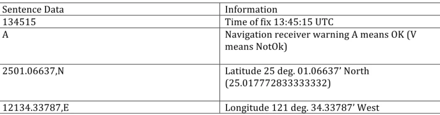
The valid GPRMC sentence mentioned above contains the following information:
Table 2 -‐ NMEA $GPRMC sentence information
Sentence Data Information
134515 Time of fix 13:45:15 UTC
A Navigation receiver warning A means OK (V
means NotOk)
2501.06637,N Latitude 25 deg. 01.06637’ North
(25.017772833333332)
(121.57229783333334)
0.048 Speed over the ground (measured in knots)
33.17 Course over ground
180613 Date of the fix: 18 of June 2013
*51 Checksum
Another important NMEA sentence is $GPGSV which contains information about GNSS Satellites and has the following message structure:
$GPGSV,NoMsg,MsgNo,NoSv,{,sv,elv,az,cno}*cs<CR><LF> [38] For example, in the sentences below, the number of visible satellites is 11:
a) $GPGSV,3,1,11,28,39,182,25,10,55,210,23,17,67,034,46,12,06,323,*71 b) $GPGSV,3,2,11,04,48,309,26,23,22,085,33,02,24,280,16,13,22,115,36*79 Another additional information regarding satellites in view available from $GPGSV messages is the following (on example of a) sentence above):
o Satellite ID 1 -‐ 28 (should be in the range of 1-‐32);
o Elevation 1 – 39 degrees (should be in the range of 0-‐90); o Azimuth 1 – 182 degrees (should be in the range of 0-‐359); o Signal to noise ration in dBHZ – 25 (should be in range of 0-‐99); o Satellite ID 2 – 10;
o Etc.
NMEA $GPGSA sentences contain information regarding Dilution Of Precision (DOP) and active satellites. Message structure of these messages is the following:
$GPGSA,Smode,FS{,sv},PDOP,HDOP,VDOP*cs<CR><LF> [38] As example:
Sentence $GPGSA,A,3,28,10,17,04,23,02,13,20,50,,,,3.00,1.37,2.67*08 contains the following information:
o Mode 1 – A (auto);
o Mode 1 – 3 (available values: 1 for No fix, 2 for 2D, 3 for 3D); o Satellites used -‐ 28, 10, 17, 04, 23, 02, 13, 20, 50;
o PDOP (Position dilution of precision) -‐ 3.00; o HDOP (Horizontal dilution of precision) -‐ 1.37; o VDOP (Vertical dilution of precision) -‐ 2.67
$GPGGA sentences provide information about Global Positioning System Fix Data: $GPGGA,134305.00,2501.06779,N,12134.33499,E,1,08,1.72,49.6,M,15.3,M,,*64 The following information could be extracted from this sentence:
o Time: 13:43:05;
o Latitude: 2501.06779,N (25.0177965);
o Longitude: 12134.33499,E (121.57224983333333); o Fix quality = 1 (GPS fix);
o 08 satellites in view; o HDOP = 1,72;
o Altitude = 49,6 M
As seen from the examples above, NMEA sentences provide wide range of information regarding GPS location and GPS satellites. However, NMEA does not provide original raw measurements for each satellite, such as “pseudo-‐range” and “Doppler shift” required by RTKLib and RTK technology in general. On the other hand, UBX protocol (and the other binary protocols) includes these data.
UBX is a proprietary protocol used in u-‐blox GPS receivers. UBX messages that contain necessary for RTK information are RXM-‐RAW (Raw Measurement Data) and RXM-‐SFRB (Subframe Buffer). According to [38], payload of RXM-‐RAW messages contains the following information:
o Measurement integer millisecond GPS time of week; o Measurement GPS week number;
o Number of Satellites;
o Carrier phase measurement; o Pseudorange measurement; o Doppler measurement; o Space vehicle number; o Signal strength
The information that is needed to work with RTKLib is Carrier phase measurement and Pseudorange measurement. This information is available in binary protocols like UBX, and never presented in NMEA.
3.1.4 RTKLib
RTKLIB – is an open source library (distributed under BSD 2-‐clause license) for “standard and precise positioning with GNSS (global navigation satellite system)”4. RTKLib supports the following positioning modes in real-‐time and post-‐processing:
4 RTKLIB: An Open Source Program Package for GNSS Positioning, http://www.rtklib.com/rtklib.htm
o Single, o DGPS, o Kinematic, o Static, o Moving-‐Baseline, o Fixed, o PPP-‐Kinematic, o PPP-‐Static, o PPP-‐Fixed
To calculate positioning solutions for DGPS/DGNSS, Static, Kinematic and Moving-‐baseline modes extended Kalman filter together with the GNSS signal measurement models and the troposphere and ionosphere models.
RTKLib supports wide range of external communications such as Serial connection, TCP/IP, NTRIP, local file and FTP/HTTP.
3.2 Android Application background 3.2.1. Android Platform
Android is a mobile/smartphone devices oriented operating system, built on top of Linux kernel. Basically Linux kernel is responsible for hardware communication and contains all the necessary hardware drivers. Moreover, the Linux kernel functions as an abstraction layer between the hardware and another software layers.
Figure 7 -‐ Android Architecture [33]
Figure 8 illustrates the diagram of Android Architecture from the reference cited in [33].
As shown in picture, Android platform consist of several layers, that interact with each other, and what is more important – function as a service provider for an upper layer. Every application is run in its own separate instance of Dalvik Virtual Machine.
3.2.2 Android programming languages and developer tools
Java is one of the officially supported programming languages for Android applications development. Additionally, there is Android NDK that designed to support native-‐code languages implementation such as C and C++. Moreover, Google extended the list of supported programming languages by launching the Android Scripting Environment (ASE), that allows building simple Android applications using popular dynamic scripting languages such as Python, Perl, JRuby, Lua, BeanShell, JavaScript, Tcl.
Android SDK is the set of API libraries and developer tools that are necessary to build, test, and debug apps for Android.
The Android Developer Tools (ADT) is a powerful plugin for Eclipse developed by Google that helps to build, test and debug Android apps. It support both Java programming and Native Development (C, C++).
3.2.3 Access smartphone sensors with Android
Android provides API that allows to access built-‐in sensors, responsible for measuring orientation, motion, and several other environmental conditions such as humidity, air temperature, pressure, and illumination. The Android sensor framework guarantees flexible access to these sensors and allows acquiring raw sensor data.
To monitor this raw sensor data two callback methods have to be implemented:
onAccuracyChanged() and onSensorChanged(), that are both exposed through the SensorEventListener interface.
For travel location-‐oriented applications, the geomagnetic field sensor (to track changes in magnetic field of the earth) and accelerometer (to get a compass bearing) could be used.
3.2.4 Android Application Components
There are four types of android application components that appear to be the fundamental blocks to build an application5:
Table 3 -‐ Android Application Components
Activities An activity is the most common component
for each app. Every app is supposed to have at least one activity, which represents a single screen with an UI.
Services Service is a component that does not require
an UI and it runs in background.
Content providers A content provider designed to provide
access to a shared data between different apps.
Broadcast receivers A broadcast receiver is responsible to react on broadcast messages from the other apps or from the system.
3.2.5 Google Cloud Messaging Service
Google Cloud Messaging for Android (GCM) is a free service supported by Google, that allows to send small messages from an external server to an android app. There are two types of messages supported by GCM:
• Send-‐to-‐sync messages, and • Messages with payload
The main difference between these two types of messages is that the latter ones are always delivered. In contrast, send-‐to-‐sync messages designed to just notify an app that it needs to sync data from the server. Messages with payload can be up to 4kb and be sent in a JSON-‐ formatted message: { 'registration_ids' : registration_id, 'data': { 'location' : msg } }
3.3 Geospatial Analysis Background
5 As mentioned in Android Development Guide:
This section describes general terminology, techniques, and tools and associated formulas used for determination of location positioning, distance measurements. Description of used open-‐source geographic information systems (GIS), related software and available frameworks and programming facilities for spatial analysis is also included in this section.
3.3.1 Calculating distance between two given points
Great-‐circle distance
Great-‐circle distance formula is based on a spherical model of the earth and uses average great-‐circle radius equal 6371 kilometers.
To calculate the distance between two given points Point1=(latitute1, longitude1) and Point2=(latitude2, longitude2) great-‐circle distance formula was used:
𝑑𝑖𝑠𝑡𝑎𝑛𝑐𝑒 = arccos (sin (𝑙𝑎𝑡𝑖𝑡𝑢𝑑𝑒1) · sin (𝑙𝑎𝑡𝑖𝑡𝑢𝑑𝑒2) + cos (𝑙𝑎𝑡𝑖𝑡𝑢𝑑𝑒1) · cos (𝑙𝑎𝑡𝑖𝑡𝑢𝑑𝑒2) · cos (𝑙𝑜𝑛𝑔𝑖𝑡𝑢𝑑𝑒1 − 𝑙𝑜𝑛𝑔𝑖𝑡𝑢𝑑𝑒2) ) · 𝑅
(2)
where R is the average great-‐circle radius.
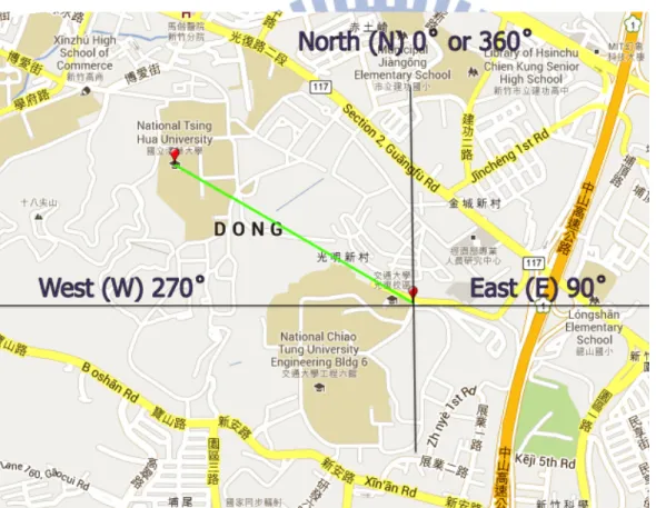
For example, to calculate distance between NCTU (24.789345,120.999867) and NTHU (24.794463,120.990142), the following steps are required:
• Convert latitude and longitude measured in degrees to radians using formula: 𝑅𝑎𝑑𝑖𝑎𝑛𝑠 = 𝐷𝑒𝑔𝑟𝑒𝑒𝑠 ∗ 𝑃𝐼 / 180
NCTU (24.789345, 120.999867) = (0.4326556896627937 rad, 2.1118460736252334 rad) NTHU (24.794463, 120.990142) = (0.43274501561391077 rad, 2.1116763403554772 rad)
• Calculate distance using great-‐circle distance formula mentioned above 𝑑𝑖𝑠𝑡𝑎𝑛𝑐𝑒 = 𝑎𝑟𝑐𝑜𝑠 𝑠𝑖𝑛 0.4326556896627937 · 𝑠𝑖𝑛 0.43274501561391077 + 𝑐𝑜𝑠 0.4326556896627937 · 𝑐𝑜𝑠 0.43274501561391077 · 𝑐𝑜𝑠 2.1118460736252334 − 2.1116763403554772 · 6371 = 1.1347336565854425 𝑘𝑚
Great-‐circle distance in Python could be calculated using math module: >>> from math import cos, sin, acos
>>> acos(sin(0.4326556896627937) * sin(0.43274501561391077) + cos (0.4326556896627937) * cos (0.43274501561391077) * cos (2.1118460736252334 -‐ 2.1116763403554772)) * 6371 1.1347336565854425
![Figure
1
-‐
Studies
[2]
proposed
system
architecture](https://thumb-ap.123doks.com/thumbv2/9libinfo/8134503.166375/13.892.131.767.453.1055/figure-studies-proposed-architecture.webp)
![Figure
3
-‐
Errors
on
GPS
Signal
[41]](https://thumb-ap.123doks.com/thumbv2/9libinfo/8134503.166375/16.892.129.822.420.1085/figure-errors-on-gps-signal.webp)