A New Power Collection
Architecture for Future
Spacecraft
MING YING KUO MEI SHONG KUO
National Chiao Tung University Taiwan
CHING CHUAN KUO
Industrial Technology Research Institute Taiwan
The generalized tree-like transmission line network system having n layers in total with m-to-1 branch connection at each joint (T-TLNS-n-m) is proposed to replace the traditional series-parallel combined dc networks to automatically accumulate identically distributed power cells into the large amount of useful power for the spacecrafts. The proposed system has the attractive features of simple structure, easy construction and maintenance, and low cost, because two kinds of parts, ac current sources and m-to-1 transmission line (TL) branch connection parts, are used in the whole system. A method of implementing ac current cells having high output impedance is proposed to improve the power collection efficiency of the whole network system. Simulated results show that that low-pass nominal ¼- or T-circuit with high characteristic impedance, which is used for the voltage source to current source converter in the current cell, improves the efficiency of the voltage inverter, filters out the harmonics, and increases the output impedance of the whole current cell.
Manuscript received February 20, 1996; revised September 24, 1996.
IEEE Log No. T-AES/33/4/06849.
Patents have been applied for for the appropriate contents of this manuscript.
Authors’ addresses: M. Y. Kuo and M. S. Kuo, Dept. of Electronics Engineering and Institute of Electronics, Engineering Bldg. 4IV, National Chiao-Tung University, 1001 Ta Hsueh Rd., Hsinchu, 300, Taiwan, R.O.C.; C. C. Kuo, Computer and Communication Research Laboratories, Industrial Technology Research Institute, Taiwan, R.O.C.
0018-9251/97/$10.00 c° 1997 IEEE
I. INTRODUCTION
For space navigation, electric power is everything. The energy sources of the spacecraft can be from solar light or a rain of energetic particles from the universe. The common features of these energies are that the amount of energy on the locally small area is little and is not usually stable and therefore useless. The amount of energy over a large area becomes larger and useful if it is collected effectively and stored safely.
Many solar modules have been developed to transfer solar light into electricity [1]. If every identical renewable energy is converted into dc electric energy by highly efficient dc-to-dc or ac-to-dc converters with maximum power point tracking (MPPT) [2—3], high regenerative power supply could be traditionally created by directly connecting these dc sources in parallel, in series, or in series-parallel via dc mains. However, the series and parallel circuit networks have some drawbacks, such as the reduction of power collection efficiency resulting from connecting a large number of nonideal sources, the ratings of sources, and the complexity of network construction increasing with increasing the number of sources, etc. Additionally, the series-parallel combined structure has the potential of optimum power collection efficiency, but there are still some problems that once some unbalanced power supply modules happen, this makes the defect or weak modules inversely get charged. It had been found that adding a great number of blocking diodes and bypass diodes into these traditional network system protects each power source from being charged [4]. However, these diodes contribute to energy loss, which cannot be negligible in the case of large amount of sources.
The presented two-dimensional ac-type power collection network system is simply created by using the shunt connection to connect transmission lines (TLs) (such as the coaxial cables) in parallel like a tree with its branches regularly branching out all around. By utilization of the TL theory and the concept similarly used in the phase-array antenna, the power coming from every cell is automatically accumulated and directed toward the target load along the tree-like network. It is to be emphasized that all the cell units share the same single minimum voltage and current rating of the system while the absolute maximum of voltage and current exist only at the output target load of network; the TL network itself linearly bears the increased voltage and current. The proposed tree-like network system has the attractive features of simple structure, easy construction and maintenance, and low cost, because only two kinds of parts, ac current sources and m-to-1 TL branch connection parts, are used in the whole system.
This work addresses the tree-like two-dimensional TL structure in Section II. Comparing this tree-like
network system with comb-like network systems, which have been proposed in [6—8], the comb-like systems are found to be difficult in construction and maintenance because sources inside the system have different voltage, current, and power ratings and have different power factors. This newly presented tree-like network is a much improved system over the comb-like networks and the conventional series-parallel combined dc networks.
It has been shown that the presented tree-like network system has higher power collection efficiency with growing the equivalent output impedance of current cell. Section III describes one of many possible methods to implement ac current sources having high output impedance, i.e., to cascade the phase-controlled series-resonant voltage inverter having low output impedance, for example, with the voltage source to current source converter and the step-up transformer into the phase-controlled resonant current source cell.
The simulated results in Section IV show that lump-type low-pass ¼- or T-circuit with high
characteristic impedance, which is used for the voltage source to current source converter in the current cell, improve the efficiency of the voltage inverter, filter out harmonics, and increase the output impedance of the whole current cell.
II. TREE-LIKE TRANSMISSION LINE NETWORK SYSTEMS
A. Important Properties of a Quarter-Wavelength Transmission Line
The input impedance of a lossless TL having the characteristic impedance ZO and the length l, and terminated by a load ZL is
Zi= ZOZL+ jZOtan(¯l)
ZO+ jZLtan(¯l) (1)
where ¯ is the phase constant, ¸ is the wavelength, and ¯ = 2¼=¸. A quarter-wave lossless TL is described by an important relation:
Zi=Z 2 O
ZL: (2)
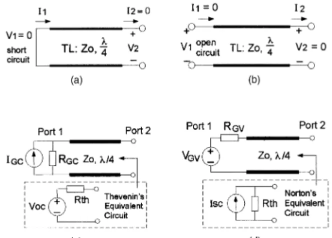
Fig. 1(a)—(b) shows a quarter-wave lossless TL terminated with two different terminations at port 1: the short-circuit terminal and the open-circuit terminal. A quarter-wave lossless TL converts the load impedance into an input impedance by (2). So, a quarter-wave lossless TL, which is terminated with an open circuit, has a short circuit impedance at the input terminals, and a quarter-wave lossless TL, terminated with a short-circuit, has an open-circuit input impedance. In Fig. 1(a), we have the phasor voltage and current relationships between the input
Fig. 1. Equivalent circuits of quarter-wave lossless TL, which is terminated with different loads at port 1. (a) Short circuit. (b) Open circuit. (c) Parallel-connection pair of IGC and RGC.
(d) Series-connection pair of VGV and RGV.
and output ports:
V2= ZOI1exp³¡j¼ 2 ´
(3) and V1= 0 and I2= 0. Similarly, we determine in Fig. 1(b): I2= V1 ZOexp ³ ¡j¼ 2 ´ (4) and I1= 0 and V2= 0.
Fig. 1(c) shows that a current source, which has a short-circuit output current IGC and an internal impedance RGC, is at the port 1, and based on (2)—(3), the Thevenin’s equivalent circuit at port 2, looking backward into TL, is Voc= ZOIGCexp³¡j¼ 2 ´ and Rth= Z 2 O RGC: (5) In addition, Fig. 1(d) shows that a quarter-wave TL is terminated by a voltage source, which has the open-circuit output voltage VGV and an internal impedance RGV at port 1, and based on (2) and (4), the Norton’s equivalent circuit at port 2 has
Isc=VGV ZO exp ³ ¡j¼2´ and Rth= Z 2 O RGV: (6) Equations (5)—(6) facilitate the analysis of the tree-like TL network systems in the next section.
B. Analysis of Tree-Structure Network
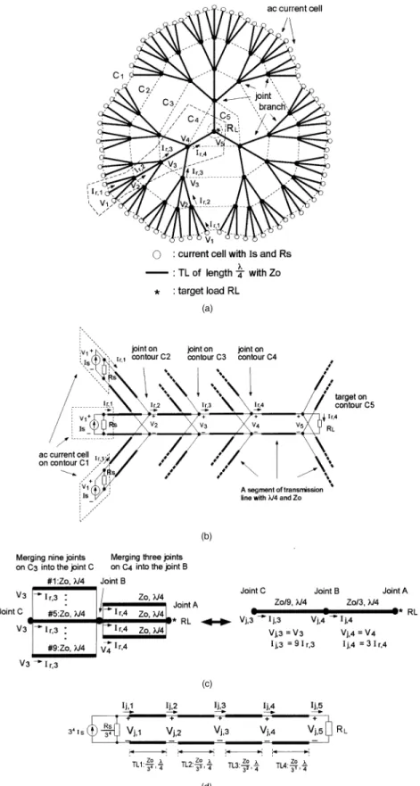
Fig. 2(a) shows a small system of the tree-like TL power collection network which contains successive 5 layers in total with 3-to-1 branch connection at each joint. Each segment of TL has the length of ¸=4 and characteristic impedance ZO. All the distributed power sources are unified and identical ac current
Fig. 2. Graph for tree-like TL network system has 5 layers with 3-to-1 branch connection at each joint (T-TLNS-5-3). (b) Illustration explains practical connection of T-TLNS-5-3. (c) Those TLs between two merging joints can be equivalently lumped into one segment
of TL. (d) Equivalent TL circuit derived from applying merger procedure to T-TLNS-5-3.
cells, which has an output current IS and an internal impedance RS. The system target load is RL. The tree-like system has an arrangement of the central-symmetry with respect to RL. Fig. 2(b) illustrates
the practical connection of the tree-like network. It has 5 layers, and each layer is indicated by a dotted-line contour Ck. All current cells are connected to the contour C1, contours C2to C4
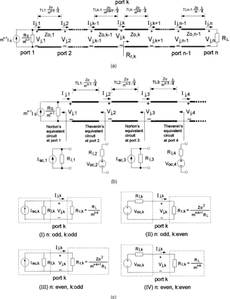
Fig. 3. TL circuit obtained by applying merger procedure to T-TLNS-n-m. (b) Determine Norton’s equivalent circuit for odd port k and Thevenin’s equivalent circuit for even port k. (c) Equivalent circuit at kth port has four possible circuits which are dependent on pair of
integers n and k being odd or even.
contain joints only, and the contour C5contains one joint and the target RL. We have derived a generalized
tree-like TL network system, which has n layers in total with m-to-1 branch connection at each joint, and is abbreviated by T-TLNS-n-m. The tree network system
shown in Fig. 2(a) has 5 layers with 3-to-1 branch connection at each joint. It is therefore represented by T-TLNS-5-3.
All current cells are synchronized with one another, and it makes every joint on the same contour Ck have the same phasor voltage, denoted by Vk, and the same phasor current toward the target, denoted by Ir,k. Merging together those joints on the same contour does not affect the stability of the system. Fig. 2(c) illustrates that three joints on C4are merged into joint B, and it makes three TLs become the parallel arrangement between joint A and B. These
three lines can be represented by one segment of TL whose characteristic impedance is ZO=3, and the merging TL has the relations of Vj,4= V4and Ij,4= 3Ir,4. When merging nine joints on C3 into joint C, the parallel connection of nine TLs between joint B and C is equivalent to one segment of TL whose characteristic impedance is ZO=9, and this merging line has the equations of Vj,3= V3and Ij,3= 32I
r,3. The same merger procedure applies to the other contours of T-TLNS-5-3. Especially, merging 34 current cells is equivalent to one current source whose output current and internal impedance are 34I
S and RS=34, respectively. The equivalent TL circuit is shown in Fig. 2(d).
Similarly, the TL circuit, as shown in Fig. 3(a), is derived from the application of the merger procedure described previously to T-TLNS-n-m. The characteristic impedances of n¡ 1 segments of
quarter-wavelength TL become a power series: ZO,1= ZO mn¡1, ZO,2= ZO mn¡2, ZO,3= ZO mn¡3, : : : , ZO,n¡1= ZO m1 (7)
where ZO,k is the characteristic impedance of the kth segment of TL, TLk. In Fig 3(a), the Vj,k and Ij,k have relationships with Vk and Ir,k of T-TLNS-n-m as follows:
Vj,k= Vk (8)
Ij,k= (Number of branch TLs between Ck and Ck+1)¢ Ir,k
= mn¡k¢ I
r,k (9)
where k is from 1 to n.
Fig. 3(b) illustrates that the equivalent circuit at port k, looking in the direction of source, could be the Norton’s equivalent circuit for the odd port k, which has 8 > < > : Isc,k= mn¡(k+1)=2ISexp μ ¡j(k¡ 1)¼2 ¶ Rl,k= RS
mn¡k for an odd integer k
(10)
and the Thevenin’s equivalent circuit for the even port k, which has 8 > > < > > : Voc,k= m(k¡2)=2ISZOexp μ ¡j(k¡ 1)¼2 ¶ Rl,k= 1 mn¡k+1¢ Z2 O
RS for an even integer k (11)
as based on (2) and (5)—(6). In addition, the definition of Rr,k is the equivalent input impedance at port k, obtained by looking toward the target RL, and it is written as Rr,k= 8 > > < > > : 1
mn¡k ¢ RL for an even integer (n¡ k) 1
mn¡k+1¢ Z2
O
RL for an odd integer (n¡ k) :
(12) By combining (10)—(11) with (12), the equivalent circuit at port k has four possible circuits and each is dependent on the pair of integer n and k being even or odd, as shown in Fig. 3(c). They facilitate the determination of the Vj,k and Ij,k. Then, Vk and Ir,k of T-TLNS-n-m can be derived from (8)—(9). We define the notation of Pr,k=12VkIr,k as the complex power transmitting toward the target RL at each joint of the contour Ck, where Ir,k is the complex conjugate of Ir,k. We summarize Vk, Ir,k, and Pr,k for each joint on the contour Ck as follows.
1) For the T-TLNS-n-m having even n layers,
a) if the joint on the odd contour Ck, i.e., k is odd, then Vk= m(k¡1)=2 ISRSZ 2 O mRSRL+ Z2 O exp μ ¡jk¡ 12 ¼ ¶ (13) Ir,k= m(k+1)=2 ISRSRL mRSRL+ Z2 O exp μ ¡jk¡ 12 ¼ ¶ (14) Pr,k=1 2m k jISj2R2SRLZO2 (mRSRL+ Z2 O)2 (15) b) if the joint on the even contour Ck, i.e., k is even, then Vk= mk=2 ISRSRLZO mRSRL+ Z2 O exp μ ¡jk¡ 12 ¼ ¶ (16) Ir,k= mk=2 ISRSZO mRSRL+ Z2 O exp μ ¡jk¡ 12 ¼ ¶ (17) Pr,k=1 2m k jISj2RS2RLZO2 (mRSRL+ Z2 O)2 : (18)
2) For the T-TLNS-n-m having odd n layers,
a) if the joint on the odd contour Ck, i.e., k is odd, then Vk= m(k¡1)=2ISRSRL RS+ RLexp μ ¡jk¡ 12 ¼ ¶ (19) Ir,k= m(k¡1)=2 ISRS RS+ RLexp μ ¡jk¡ 12 ¼ ¶ (20) Pr,k=1 2m k¡1 jISj2R2SRL (RS+ RL)2 (21)
b) if the joint on the even contour Ck, i.e., k is even, then Vk= m(k¡2)=2ISRSZO RS+ RLexp μ ¡jk¡ 12 ¼ ¶ (22) Ir,k= mk=2 ISRSRL ZO(RS+ RL)exp μ ¡jk¡ 1 2 ¼ ¶ (23) Pr,k=1 2m k¡1 jISj2R2SRL (RS+ RL)2: (24) C. Important Properties
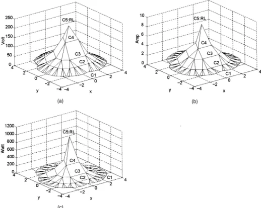
Note that the ratio ofjVk+1j=jVkj and jIr,k+1j=jIr,kj of T-TLNS-n-m are out of all relation to an internal impedance RS of current cell. When the target load satisfies the condition of 1=m < RL=Z0< 1, the amplitudes of voltage Vk and current Ir,k increase in the direction of the target load, as derived from the conditions of jVk+1j=jVkj > 1 and jIr,k+1j=jIr,kj > 1. It implies that cell units share the absolute minimum voltage and current rating of the complete system while the absolute maximum voltage and current in the complete T-TLNS-n-m occur at the target load. Moreover, the TL network itself linearly bears the difference between absolute extremes of voltage drop and current flow. Fig. 4 shows the simulation
Fig. 4. Three-dimensional plots of (a)jVkj, (b) jIr,kj, (c) jPr,kj of T-TLNS-5-3 at ZO= 50−, RL= 25−, IS= 1 exp(¡j0)A, and RS=1,
where xy-plane represents position of cells or joints and z-axis stands for amplitude.
results of T-TLNS-5-3 at IS= 1 exp(¡j0)A, RS=1, ZO= 50−, and RL= 25− to illustrate the previous analysis.
Note that the maximum ofjPr,kj equals 1
83 k¡1jI
Sj2RS, which locates at the condition of mRSRL= Z2
O for T-TLNS-n-m having even n layers and at the condition of RL= RS for T-TLNS-n-m having even n layers. For a fixed value of RS, RL at the extreme point ofjPr,kj has relation to the number of branches m and the characteristic impedance ZO for the systems having even n.
In addition, Pr,k is real because Vr,k is in phase with Ir,k. The magnitude of Pr,k is growing with increasing RS; that means that the larger the internal impedance RS of nonideal cell, the more power the system collects. The fact ofjPr,k+1j = 3 ¢ jPr,kj emphasizes that the T-TLNS-n-m is capable of accumulating the small power cell step by step in the direction of the system target RL and forms large amount of power at RL.
It had been shown that this tree-like network has the same efficiency as the conventional series-parallel combined dc networks. Moreover, one of the
important features of T-TLNS-n-m is that when damaged cells appear and are short circuited, the self-stability makes some sources sustain additional power to compensate for the power which is supposed to be supplied by those damaged cells. It makes the tree-like network with some damaged cells provide almost the same amount of power as the system without any damaged cells. Although this network
system has the same collection efficiency as the optimum series-parallel networks, from other system points of view, the proposed tree-like T-TLNS-n-m is much better than the traditional series-parallel networks [9].
III. IMPLEMENTATION OF AC CURRENT CELL A. Voltage Source to Current Source Converter
1) Quarter-Wave Lossless TL: A segment of quarter-wavelength lossless TL can be considered as a voltage source to current source converter (V-to-C converter). We define ZO,C as the characteristic impedance of V-to-C converter. Fig. 5 shows that the V-to-C converter links the load RL,N and the ac voltage source which has an open-circuit voltage VOC and an internal source impedance Rin. The output current IO through RL,N is obtained by using (6):
IO= Z 2 O,C Z2 O,C+ RinRL,N ¢ VOC ZO,Cexp ³ ¡j¼2´: (25) The smaller value of Rin and the larger value of ZO,C are chosen so that IOapproaches the phasor value VOC=ZO,Cexp(¡j(¼=2)). If 10RinRL,N· Z2
O,C holds, the magnitude of IO can have less than 1% deviation from the value ofjVOC=ZO,Cj. In this way, IO is almost independent of RL,N. Therefore, the larger ZO,C value is selected so that the V-to-C converter would convert
Fig. 5. Quarter-wave lossless TL is used for V-to-C converter.
Fig. 6. (a) Equivalent ¼ circuit, (b) nominal ¼ circuit, (c) equivalent T circuit, (d) nominal T circuit of quarter-wave
lossless TL.
one nonideal ac voltage source into one ac current source which is as close to the ideal case as possible.
2) Equivalent Lumped Circuits of Quarter-Wave
Lossless TL: A segment of lossless TL used as the V-to-C converter, can be represented by the equivalent ¼ circuit, as shown in Fig. 6(a), where the series arm has the impedance of jZO,Csin(¯l) and the two shunt arms have the same admittance of jYO,Ctan(¯l=2). For the quarter-wave lossless TL, we have ¯l = ¼=2, and hence, the impedance of the series arm is jZO,C and the admittance of the shunt arm is jYO,C.
The nominal ¼ circuit in Fig. 6(b) at a frequency fs= !s=2¼ is requested to be equivalent to the equivalent ¼ circuit of a quarter-wave lossless line, where fs must satisfy the relationship of fs¢ ¸ = ¹p and ¹pis the phase velocity. Therefore, the series arm and the shunt arms satisfy the relations of j!sL = jZO,C and j!sC = jYO,C, and we have the design formula as follows:
L =ZO,C
!s and C =
1
!sZO,C: (26) Similarly, the equivalent T circuit shown in
Fig. 6(c) can also be used as an equivalent circuit of the quarter-wave lossless line. The nominal T circuit in Fig. 6(d) is to have its shunt capacitor and series inductors satisfy the relationship of ZO,C= !sL = 1=!sC. The values of series inductance L and the shunt capacitance C of the nominal T circuit are the same as those of the nominal ¼ circuit.
B. Phase-Controlled Full-Bridge Series-Resonant Voltage Inverter
We analyze the output equivalent circuit of the phase-controlled full-bridge series-resonant
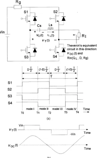
Fig. 7. (a) Phase-controlled full-bridge series-resonant voltage inverter. (b) Waveform of fundamental component of vT(t) is
output voltage vOC(t) with RI open circuited.
inverter whose four switches operate at the same frequency as the series-resonant load. Fig. 7 shows the phase-controlled full-bridge series resonant voltage inverter and the gate drive voltage waveforms of the four switch transistors in the bridge. Switching leg, including S1and S3, is loaded capacitively. Switches S1and S3 are thus zero-current switching (ZCS) and suffer from turn-on loss but no turn-off loss. Additionally, switches S2and S4are zero-voltage switching (ZVS), and they have the turn-off loss and no turn-on loss, because the other switch leg is loaded inductively.
It is assumed that the components LS, CS, and four switches are lossless, and Rg is an internal impedance of dc voltage source. The four switches operate at the same frequency fswas the load series-resonant frequency fr. D is defined as the duty cycle of the quasi-square wave applied to the tank, and (1¡ D) corresponds to the relative phase shift among the switches of the bridge. We control the output load voltage by varying D.
The equivalent output circuit of the voltage inverter contains the open-circuit voltage, vOC(t), and
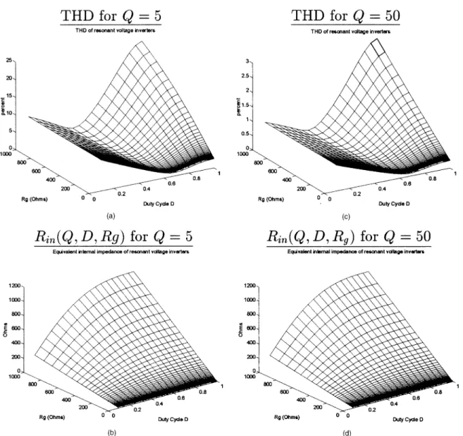
Fig. 8. Three-dimensional representation of THD and internal impedance Rin(Q, D, Rg) of phase-controlled series-resonant voltage inverter versus D and Rg at (a)—(b) Q = 5 and (c)—(d) Q = 50.
the output impedance, Rin, connected in series. Since fsw= fr, the series resonant tank has zero phase shift at fundamental frequency, and the output impedance of inverter is purely resistive and is a function of Q, D, and Rg. We denote the output impedance by Rin(Q, D, Rg).
To determine vOC(t) mathematically, let the series-resonant inverter operating at fsw= fr have the loaded quality factor Q:
Q =!rLS RI =
1
!rCSRI (27)
where !r= 2¼fr= 1=pLSCS. It is assumed that Q is such a large value that the high-frequency harmonics at the output of the inverter are negligible. With RI open-circuited, the fundamental component of the voltage vT(t) applied to the tank is equal to vOC(t)
vOC(t) = 4 ¼¢ Vin¢ sin ³¼ 2D ´ ¢ sin(2¼fswt): (28)
The magnitude of vOC(t) is controlled by the duty cycle D and is proportional to the sin function of D. The phase-controlled voltage inverter is inherently a voltage source because vOC(t) does not vary with the load RI under high Q.
With RI connected, the fundamental component of iL(t) is denoted by iL,f(t). We get Rin(Q, D, Rg) by using the following relation
iL,f(t) = vOC(t) Rin(Q, D, Rg) + RI ) Rin(Q, D, Rg) =
vOC(t)
iL,f(t) ¡ RI: (29) The voltage inverter is simulated under the conditions of different values of Rg, D, and Q. Fig. 8 shows the total harmonic distortion (THD) of the output current through RI and an internal impedance Rin versus Rgand D at Q = 5 and Q = 50. Note that THD is decreased with increasing Q and the minimum
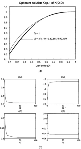
Fig. 9. Optimum solution Kop,1(Q, D) of K(Q, D) of Rin(Q, D, Rg) = K(Q, D)¢ Rg in least-square error sense.
(b) Polynomial of a¢ Q3+ b¢ Q2+ c¢ Q + d is used to fit curves of
Kop,1 in least-square error sense.
of THD locates at about D = 0:7. The curves of Rin(Q, D, Rg), which are linearly increased with Rg, is to be fitted with the relation of Rin(Q, D, Rg) = K(Q, D)¢ Rgin a least-square error sense. The optimum solutions of K(Q, D), denoted by Kop,1, are plotted in Fig. 9(a). To describe it mathematically, we define a polynomial of degree 3 as Kop,2= a¢ D3+ b¢ D2+ c¢ D + d. and let K
op,2= Kop,1(Q, D), after solving the coefficients of the polynomial in a least-square error sense to each case of Q. Fig. 9(b) shows the plots of the coefficients a, b, c, and d versus Q and coefficients approach the constant value for high Q values. We can estimate the output impedance Rinof the inverter for Q¸ 5 as:
Rin(Q, D, Rg) = (0:3D3¡ 1:8D2+ 2:5D¡ 0:04) ¢ Rg: (30) The effect of the internal impedance Rg of dc voltage source on the output impedance of the inverter is nonlinear. The output equivalent circuit of the
Fig. 10. Phase-controlled resonant current cell contains three cascaded stages of phase-controlled full-bridge series-resonant voltage inverter, V-to-C converter, and step-up transformer.
inverter is therefore determined and is described by (28) and (30).
C. Phase-Controlled Resonant Current Cell
It has been found that the phase-controlled series and series-parallel resonant inverter in [12—13] have much smaller output impedance than the phase-controlled parallel resonant inverter in [14]. It is noted that cells in T-TLNS-n-m should have large output impedance to improve the power collection efficiency. A simple voltage inverter is not qualified for our tree-like network system. The phase-controlled series-resonant voltage inverter in this work has the output impedance as nonlinear function of the internal resistance Rgof dc voltage source, and its output impedance is usually low because large stabilized shunt capacitor is used to represent dc source. One of the main purposes of this section is to present a method to change the low output impedance of the voltage inverter into the high output impedance.
Fig. 10 shows that the voltage inverter is cascaded with the V-to-C converter and the step-up transformer with a ratio of NT. Equation (25) states that the V-to-C converter can convert the voltage source with low output impedance into the current source with high output impedance by increasing ZO,C. The step-up transformer magnifies the impedance again in addition to providing the electric isolation. We call the circuit in Fig. 10 a practical ac current source cell.
Based on (6), (28), and (30), we can obtain the equivalent output circuit of the current cell for Q¸ 5 as follows: IS= Voc NTZO,Cexp ³ ¡j¼2´ = 4Vin ¼NTZO,Csin ³¼ 2D ´ exp³¡j¼ 2 ´ (31) RS= N 2 TZO,C2 Rin(Q, D, Rg) = N 2 TZO,C2 (0:3D3¡ 1:8D2+ 2:5D¡ 0:04) ¢ R g : (32)
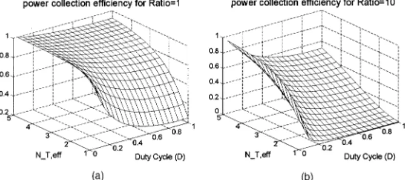
Fig. 11. Three-dimensional representation of power collection efficiency ÃN,L of T-TLNS-n-m versus Nt,eff and D at (a) Ratio = 1 and (b) Ratio = 10.
The current cell is required to have larger internal impedance RS so as to behave closer to that of the ideal ac current source. It can be achieved by selecting the small value of Rg and large value of D or increasing ZO,C and the ratio NT.
It is found that if the current cell contains the low-Q phase-controlled series-resonant voltage inverter and a quarter-wavelength lossless TL section as the V-to-C converter, the choice of low Q value in the voltage inverter achieves high efficiency, but low Q circuit is rich in harmonics which is not good for the power collection system. Since the TL section does not reduce the hamonics effectively, the low-pass nominal ¼ or T circuit in Fig. 6 are used as the V-to-C converter to filter out the harmonics and to obtain a synchronous, single frequency current cell system. IV. SIMULATED RESULTS
By substituting k = n into (18) and (21), the derived Pr,nis the the power received by the target RL in T-TLNS-n-m. The notation of PL,ideal represents the power received by RL under RL6= 0 and RS=1. The denotation of ÃN,L is defined as the ratio of Pr,n to PL,idealand called the power collection efficiency of T-TLNS-n-m. As the resonant current inverter in Fig. 10 is in place of all cells in T-TLNS-n-m, we can obtain ÃN,L: ÃN,L= Ã 1 + f(D) N2 T,eff ¢ Ratio !¡2 (33) where f(D) = 0:3D3¡ 1:8D2+ 2:5D¡ 0:04 (34) NT,eff= ½pm¢ N
T for an even integer n
NT for an odd integer n (35)
Ratio = 8 > > > < > > > : Rg¢ ZO2 RL¢ Z2 O,C
for an even integer n Rg¢ RL
Z2 O,C
for an odd integer n :
(36)
The simulated results of the power collection
efficiency of T-TLNS-n-m are shown in Fig. 11. The power collection efficiency for a small Ratio value is higher than that for a large Ratio value. And, the efficiency is very sensitive to the variations of NT,eff and D at the case of the large Ratio.
For the case of T-TLNS-5-3, it is assumed that all transmission lines in the tree-like network have ZO= 50− and the system target load is RL= 50−. Note that the load impedance of current cell is RL,N= V1=Ir,1= RL, as derived from dividing (19) by (20), and the load impedance of voltage inverter equals RI= Z2
O,C=RL,N. The circuit parameters of the phase-controlled full bridge series-resonant voltage inverter are Vin= 100 V, Rg= 10−, D = 0:26, fsw= 1 MHz and Q = 5, and LS= 0:159 mH and CS= 796 pF are obtained by (27). Additionally, the V-to-C converter has ZO,C= 100−, and its nominal ¼-circuit and nominal T circuit have L = 15:9 uH and C = 159 pF as given by (26). The turn ratio of the step-up transformer is set to NT= 1. It is derived that the current cell has the short-circuit current IS= 0:5¢ exp(¡j(¼=2)) A and the output impedance RS= 2026−, as obtained by (31)—(32).
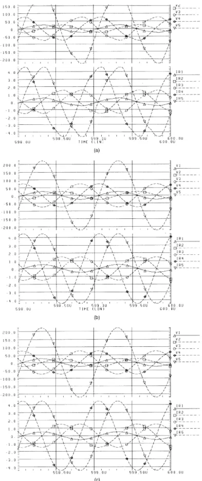
The SPICE simulation results of T-TLNS-5-3 described above are shown in Fig. 12. It has excellent agreement with the previous analysis of T-TLNS-n-m. Additionally, the caculated efficiency of T-TLNS-5-3 is ÃL,N= 98:6%. The THD is caculated by taking into account from the second harmonic to the tenth harmonic together. The simulation results in Fig. 12 point out that THD of vk(t) and ir,k(t) of T-TLNS-n-m for the lump-type low-pass V-to-C converter, such as the nominal ¼ and T circuit, is much small than that for the TL-type V-to-C converter. Note that if the low-pass nominal ¼- or T-circuit are used for the V-to-C converter in the current cell, the low-Q series-resonant voltage inverter is selected to achieve high efficiency and the harmonics from the low-Q voltage inverter can be reduced effectively by the next stage of the low-pass ¼ or T circuit. Thus the high-efficiency and low-harmonic characteristics can be obtained by cascading low-Q series-resonant
Fig. 12. SPICE simulation results of T-TLNS-5-3, where every resonant current cell has fsw= 1 MHz, D = 0:26, Vin= 100 V, Rg= 10−, Q = 5, LS= 0:159 mH, CS= 796 pF, ZO,C= 100− (L = 15:9 uH and C = 159 pF) and NT= 1, and tree-like network has
ZO= 50− and target RL= 50−. Simulated results of T-TLNS-5-3 are under different types of V-to-C converters: (a) quarter-wave lossless TL section, (b) nominal ¼ circuit, and (c) nominal T circuit. THD of vk(t) and ir,k(t) are about (a) 6.2%, (b) 0.22%, (c) 0.33%.
voltage inverter with the lump-type low-pass ¼ or T filter.
Another important fact is that the equivalent load impedance, RI, of the series-resonant voltage inverter is RI= Z2
O,C=RL,N. The Q value of the voltage inverter can be reduced by increasing ZO,C, that is, the V-to-C converter equivalently increase the efficiency of the voltage inverter. It is obvious that the low-pass ¼ or T filter with high-ZO,C is used in the current cell to improve the efficiency of the voltage inverter, to filter out the harmonics, and to increase the output impedance of the whole current cell.
Therefore, those inverters which have lower output impedance can be increased to high value by cascading the low-pass type ¼ or T circuit and the step-up transformer. Thus, a new system of high power collection efficiency, low cost in maintenance and easy in implementation is presented conceptually.
V. CONCLUSIONS
This paper present a new generalized tree-like TL network system for automatically accumulating identically small power cells, which are distributed over very large areas, into large power amount at the target load along a special TL network. The tree-like network system has the attractive features of simple structure, easy construction and maintenance, and low cost, because only two kinds of parts, ac current sources and m-to-1 TL branch connection parts, are used in the whole system, and they are suitable for the mass production and should be passed through a hard reliability test process before shifting out. Thus, the system is low cost and reliable in nature that is suitable for use in future space craft.
It has been shown that the higher the output impedance of current cell, the better the power collection efficiency of T-TLNS-n-m. We propose a method to increase the output impedance of inverters by cascading the V-to-C converter and the step-up transformer. For example, the proposed phase-controlled resonant current cell, which is constructed by cascading three stages of the phase-controlled full-bridge series-resonant voltage inverter, the V-to-C converter and the step-up transformer, can achieve the high output impedance.
Increasing the characteristic impedance of the V-to-C converter is equivalent to lower the loaded quality factor, i.e., to increase the efficiency of the series-resonant voltage inverter. The harmonics resulting from the low-Q series-resonant voltage inverter should be avoided entering the tree-like TL network and forming the standing wave in network, which could damage the sources. Reducing the interference of harmonics and improving high efficiency of the series-resonant voltage inverter can
be achieved by cascading the low-pass nominal ¼ or T circuit with high characteristic impedance.
This work contributes to the important concept that there exist other methods than that of the conventional series-parallel combined dc power collection system that is used to collect many small power cells. The new one proposed here can also effectively collect the power. A practical implementation of the T-TLNS-n-m to prove its feasibility and to check its excellence and reliability are expected in a future work.
REFERENCES
[1] Edelson, E. (1992)
Photovoltaics: Solar cell update. Popular Science (June 1992), 95—99. [2] Woff, S. M. M., and Enslin, J. H. R. (1993)
Economical, PV maximum power point tracking regulator with simplistic controller.
In Proceedings of the 24th Annual IEEE Power Electronics Specialists Conference, PESC’93, 1993, 581—587. [3] Won, C. Y., Kim, D.-H., and Kim, S. C., et al. (1994)
A new maximum power point tracker of photovoltaic arrays using fuzzy controller.
In Proceedings of the 25th Annual IEEE Power Electronics Specialists Conference, PESC’94, 1994, 396—403. [4] Lasnier, F., and Gan Ang, T. (1990)
Photovoltaic Engineering Handbook. Adam Hilger 1990, 83—97. [5] Cheng, D. K. (1989)
Field and Wave Electromagnetics.
Reading, MA: Addison-Wesley, 1989, 427—508. [6] Kuo, M. Y., Kuo, C. C., and Kuo, M. S. (1995)
Novel transmission-line collection systems for photovoltaic power.
In Proceedings of the IEEE International Symposium on Circuits and Systems, ISCAS’95, 1995, 1275—1278. [7] Kuo, M. Y., Kuo, C. C., and Kuo, M. S. (1995)
Novel two-dimensional transmission-line collection systems for photovoltaic power.
Renewable Energy–An International Journal, 6, 7 (1995), 725—738.
[8] Kuo, M. Y., Kuo, C. C., and Kuo, M. S. (1996)
New transmission line systems for accumulating power from distributed renewable energy.
International Journal of Circuit Theory and Applications, 25 (1997), 43—49.
[9] Kuo, M. Y., Kuo, C. C., and Kuo, M. S. (1996) New tree-like transmission line networks for automatically accumulating the identically distributed small power cells into the large amount of useful power. IEEE Transactions on Circuits and Systems: Part I–Fundamental Theory and Applications, 1996 (revised). [10] Kazimierczuk, M. K. (1992)
Synthesis of phase-modulated dc/ac inverters and dc/dc converters.
IEE Proceedings, Pt. B, Electric Power Application, 139 (July 1992), 387—394.
[11] Kazimierczuk, M. K., and Czarkowski, D. (1995) Resonant Power Converters.
New York: Wiley, 1995.
[12] Czarkowski, D., and Kazimierczuk, M. K. (1993) Phase-controlled series-parallel resonant converter. IEEE Transactions on Power Electronics, 8, 3 (July 1993), 309—319.
[13] Czarkowski, D., and Kazimierczuk, M. K. (1993) Single-capacitor phase-controlled series resonant converter.
IEEE Transactions on Circuits and Systems, 42 (June 1993), 383—391.
Ming-Ying Kuo was born in Tainan, Taiwan, Republic of China, on August 14, 1968. He received the B.S. degree in control engineering from the National Chiao Tung University, in 1991. He is presently working toward the Ph.D. degree in electronics from the same university.
His research areas are modeling of transmission line transformers, power electronics, and networks for collecting large amount of small power cells.
Ching-Chuan Kuo was born in Tainan, Taiwan, Republic of China, on May 1, 1965. He received the B.S. degree in engineering science from the National Cheng Kung University, in 1988, and the M.S. degree in control engineering from the National Chiao Tung University, in 1990.
Since 1990, he has been working as a Design Engineer at the Computer and Communication Research Laboratories of the Industrial Technology Research Institute (ITRI). His research interests include modeling, analysis, and control techniques of power converters.
Mei-Shong Kuo was born in Tainan, Taiwan, Republic of China, on May 20, 1940. He received the B.S. degree in electrical engineering from the National Cheng Kung University, Tainan Taiwan, in 1967, and the M.S. degree in electronics from the National Chiao Tung University (NCTU) in 1969.
From 1970 to 1975, he was an instructor at the E.E. of NCTU. His interests have included the study of creating sensors for taking human arterial pulses that the ancient Chinese physicians used to do in their clinical operation,
designing signal conditioning CKTs for the respective sensors and using different techniques of signal analysis to search out related traces of some human diseases. He is also interested in the fields of 3-D sonar spectrum techniques (both
hardware and software) for a computer to get the ability to receive “mandarin speakings,” physics, modeling, applications of transmission line transformers, and renewable energy collection systems (solar energy, sea wave energy). He is presently an Associated Professor of the E.E. of NCTU.
[14] Kazimierczuk, M. K., and Czarkowski, D. (1993) A new phase-controlled parallel resonant converter. IEEE Transactions on Industrial Electronics, 40, 6 (Dec. 1993), 542—552.