Bright white light electroluminescent devices based on a dye-dispersed polyfluorene
derivative
Joo Hyun Kim, Petra Herguth, Mun-Sik Kang, Alex K-Y. Jen, Ya-Hsien Tseng, and Ching-Fong Shu
Citation: Applied Physics Letters 85, 1116 (2004); doi: 10.1063/1.1778472
View online: http://dx.doi.org/10.1063/1.1778472
View Table of Contents: http://scitation.aip.org/content/aip/journal/apl/85/7?ver=pdfcov
Published by the AIP Publishing
Articles you may be interested in
Effect of dye concentrations in blended-layer white organic light-emitting devices based on phosphorescent dyes
J. Appl. Phys. 106, 064516 (2009); 10.1063/1.3226780
Efficient white-light-emitting diodes based on polymer codoped with two phosphorescent dyes
Appl. Phys. Lett. 87, 193502 (2005); 10.1063/1.2119407
Blue phosphorescent dye as sensitizer and emitter for white organic light-emitting diodes
Appl. Phys. Lett. 85, 5403 (2004); 10.1063/1.1827326
White electroluminescence from polyfluorene chemically doped with 1,8-napthalimide moieties
Appl. Phys. Lett. 85, 2172 (2004); 10.1063/1.1793356
Bright and efficient exciplex emission from light-emitting diodes based on hole-transporting amine derivatives and electron-transporting polyfluorenes
J. Appl. Phys. 91, 10147 (2002); 10.1063/1.1481203
This article is copyrighted as indicated in the article. Reuse of AIP content is subject to the terms at: http://scitation.aip.org/termsconditions. Downloaded to IP: 140.113.38.11 On: Thu, 01 May 2014 04:14:31
Bright white light electroluminescent devices based
on a dye-dispersed polyfluorene derivative
Joo Hyun Kim, Petra Herguth, Mun-Sik Kang, and Alex K-Y. Jena)
Department of Materials Science and Engineering, Box 352120, University of Washington, Seattle, Washington 98195
Ya-Hsien Tseng and Ching-Fong Shu
Department of Applied Chemistry, National Chiao Tung University, Hsin-Chu, Taiwan, 30035, Republic of China
(Received 24 October 2003; accepted 11 June 2004)
A series of efficient and bright white light-emitting diodes were fabricated using the blends of two fluorene-derived fluorescent dyes, 共4,7-bis-共9,9,9
⬘
, 9⬘
-tetrahexyl-9H , 9⬘
H-关2,2⬘
兴bifluoren-7-yl兲-benzo关1,2,5兴thiadiazole兲 (FFBFF-emits green) and 共4,7-bis-关5-共9,9-dihexyl-9H-fluoren-2-yl兲-thiophen-2-yl兴-benzo关1,2,5兴thiadiazole兲 (FTBTF-emits red) in an efficient blue-emitting polyfluorene-derived copolymer 共poly关共9,9-bis共4-di共4-n-butylphenyl兲aminophenyl兲兲兴-stat-共9,9-bis共4-共5-共4-tert-butylphenyl兲-2-oxadiazolyl兲-phenyl兲兲-stat-共9,9-di-n-octyl兲fluorene兲 (PF-TPA-OXD). The resulting white light-emitting device reaches a maximum external quantum efficiency of 0.82% and a maximum brightness of 12 900 cd/ m2 at 12 V. The Commission Internationale d’Énclairage chromaticity coordinates of the device remain very close to that of pure white emission at a relatively broad bias range from 6 V共x=0.36, y=0.37兲 to 12 V 共x=0.34, y = 0.34兲. © 2004 American Institute of Physics. [DOI: 10.1063/1.1778472]
Recently, white organic light-emitting devices (WOLEDs) have been considered for applications in lighting and backplane light for liquid crystal displays. The ideal Commission Internationale d’Enclairage(CIE) chromaticity coordinates for WOLEDs is at x = 0.33, y = 0.33 and it should be insensitive to the applied voltage. In order to achieve this goal, numerous approaches have been explored, such as dye-dispersed poly共N-vinylcarbazole兲,1 dye-doped multilayer,2 dye-doped multilayer structures through interlayer sequential energy transfer,3–5controlling exciton diffusion,6,7triplet ex-cimers in electrophosphorescent material,8 and blends of polymers.9,10 One critical issue in the dye-doped systems is to prevent the single emission from the lower energy dopant resulting from the cascade energy transfer. Ideally, multiple emissions from both the host and the dopants should cover the required spectrum for white light. This can be achieved by controlling the concentration of the dopants and the thick-ness of the emissive layer or the hole-blocking layer.
In this letter, we demonstrate efficient white light emission from double-layer LEDs with green and red dyes dispersed in a very efficient blue-emitting host polymer. Figure 1 shows the chemical structures of a highly efficient blue-emitting polymer, 关poly共9, 9-bis共4-di共4-n-butyl-phenylaminophenyl兲兲-stat-共9,9-bis 共4-共5- 共4-tert-butylphenyl兲-2-oxadiazolyl兲-phenyl兲兲-stat-共9,9-di-n-octyl兲flouorene兲兴 (PF-TPA-OXD) containing both hole- and electron-transporting moiety as side chains,11,12 a green-emitting dye(FFBFF),13 and a red-emitting dye (FTBTF).13 Both the green- and red-emitting dyes are the derivatives of fluorene in order to enhance their compatibility with the host polymer and avoid phase separation. The EL devices were fabricated on an ITO-coated glass substrate that was pre-cleaned and treated with oxygen plasma before use. A layer of 20-nm-thick poly(ethylenedioxythiophene): polystyrene sulfonate(PEDOT, Bayer Co.) was deposited first by
spin-coating from its aqueous solution共1.3 wt %兲 and annealed at 160 ° C for 10 min under nitrogen. An emissive layer with green- and red-emitting dyes dispersed in PF-TPA-OXD was then spin-coated at 2000 rpm from its toluene solution 共⬃15 mg/mL兲 on top of the PEDOT layer. The typical thick-ness of the emissive layer was about 50 nm. Afterward, a layer of Ca 共30 nm兲 was vacuum deposited (at ⬃1 ⫻10−6Torr) on top of the emissive layer as cathode and
finally a layer of Ag共120 nm兲 was deposited as the protect-ing layer.
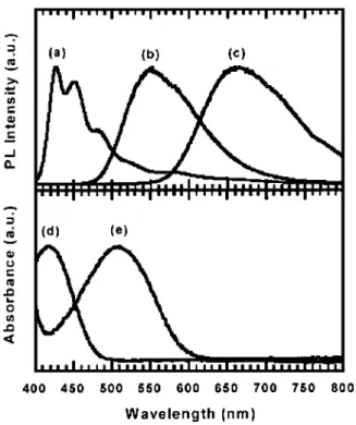
As shown in Fig. 2(a), the electroluminescence (EL) spectrum of PF-TPA-OXD shows the typical emission of polyfluorene with two intense peaks at 425 and 450 nm and a small shoulder peak at 480 nm. The UV–visible(UV–vis) and photoluminescence(PL) spectrum of FTBTF in chloro-form solution show the maximum peaks at 415 and 550 nm, respectively. Both the absorption and emission of FFBFF were redshifted due to the effect of charge transfer from fluorene to the electron-deficient benzothiadiazole moiety. In addition, the highest occupied molecular orbital (HOMO) and lowest unoccupied molecular orbital (LUMO) energy levels of FFBFF estimated from the results of cyclic volta-mmogram and UV–vis spectrum are −5.73 eV and −3.32, respectively. Compared to FFBFF, the peaks of the absorp-tion and emission spectrum of FTBTF are even more red-shifted(506 and 660 nm, respectively) because of the stron-ger charge transfer effect between the electron-donating thiophene rings and the benzothiadiazole in this compound [Figs. 2(c) and 2(e)]. The HOMO and LUMO energy levels of FTBTF are −5.62 and −3.53 eV, respectively.
In principle, the cascade energy transfer(Föster or Dex-ter type energy transfer) from the host (PF-TPA-OXD) to FFBFF and then to FTBTF should occur because the EL spectrum of PF-TPA-OXD overlaps well with the absorption spectrum of FFBFF and the PL spectrum of FFBFF also overlaps well with the absorption spectrum of FTBTF. How-ever, the energy transfer efficiency is also very sensitive to
a)Electronic mail: [email protected]
APPLIED PHYSICS LETTERS VOLUME 85, NUMBER 7 16 AUGUST 2004
0003-6951/2004/85(7)/1116/3/$20.00 1116 © 2004 American Institute of Physics
This article is copyrighted as indicated in the article. Reuse of AIP content is subject to the terms at: http://scitation.aip.org/termsconditions. Downloaded to IP: 140.113.38.11 On: Thu, 01 May 2014 04:14:31
the distance between the donor and the acceptor 共⬀ r−6兲.
Thus, it is possible to prevent efficient energy transfer by careful control of the FFBFF and FTBTF concentration in PF-TPA-OXD. On the other hand, since the energy levels of FFBFF and FTBTF are quite well matched, it may provide a
good opportunity for direct charge recombination on them (charge-trapping mechanism).
Figure 3(a) shows the EL spectrum of the device doped with 0.20 wt % of FFBFF and 0.09 wt % of FTBTF in PF-TPA-OXD(device 1). The EL spectrum shows the composite emission bands of blue, green, and orange in the whole vis-ible range 共400–750 nm兲. By comparing the data with the PL spectra of two dyes [Figs. 2(b) and 2(c)], the green-emitting band at 520 nm and the red-green-emitting band at 586 nm are from the emission of FFBFF and FTBTF, respec-tively. The CIE coordinate of device 1 changes slightly form 共x=0.30, y=0.34兲 at 6.0 V to 共x=0.32, y=0.38兲 at 12.0 V [inset to Fig. 3(b)], which is quite insensitive to the applied voltage and is close to that of the ideal CIE chromaticity coordinate for pure white color, i.e., x = 0.33, y = 0.33. Figure 3(b) shows the current density and brightness as a function of the bias voltage 共J–V–B兲. Device 1 shows a relatively low turn-on voltage at 5.0 V(defined as the voltage required to give a luminance of 1 cd/ m2). The maximum external
quantum efficiency of device 1 is calculated to be 0.82% at a voltage of 10.0 V and a current density of 0.41 A / cm2. The
maximum brightness is 15 800 cd/ m2at a voltage of 12.5 V
and a current density of 1.38 A / cm2. At this brightness, ef-ficiencies are 0.54%, 1.14 cd/ A, and 0.32 lm/ W, respec-tively. At a bias of 7.0 V, the brightness, current density, and external quantum efficiency are 405 cd/ m2, 0.061 A / cm2, and 0.31%, respectively.
In order to further improve the color purity, we have fabricated another EL device with a slightly adjusted dopant concentration (0.18 wt % of FFBFF and 0.11 wt % of FT-BTF) in PF-TPA-OXD (device 2). Figure 4(a) shows the EL FIG. 1. Chemical structure of polyfluorene derivative(PF-TPA-OXD), green (FFBFF), and red dye (FTBTF).
FIG. 2.(a) EL spectrum of PF-TPA-OXD, (b) PL spectrum of FFBFF, (c) PL spectrum of FTBTF,(d) UV–vis spectrum of FFBFF, and (e) UV–vis spectrum of FTBTF in chloroform.
Appl. Phys. Lett., Vol. 85, No. 7, 16 August 2004 Kimet al. 1117
This article is copyrighted as indicated in the article. Reuse of AIP content is subject to the terms at: http://scitation.aip.org/termsconditions. Downloaded to IP: 140.113.38.11 On: Thu, 01 May 2014 04:14:31
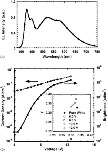
spectrum of device 2. The EL intensity of FFBFF at 520 nm is decreased and FTBTF at 586 nm is increased, indicating that the spectral change is proportional to the concentration of dyes. As shown in the inset of Fig. 4(b), the CIE coordi-nate of device 2 changes form 共x=0.36, y=0.37兲 at 6.0 V to 共x=0.34, y=0.34兲 at 12.0 V, which are also quite insensitive to the applied voltage and are very close to that of the pure white color. As shown in Fig. 4(b), the turn-on volt-age of device 2 is the same as that of device 1. The maxi-mum external quantum efficiency is 0.89% at a voltage of 10.0 V with a current density of 0.41 A / cm2. The maximum brightness for white emission as depicted in Fig. 4(b) is 12 900 cd/ m2at a voltage of 12.5 V and a current density of
1.23 A / cm2. The efficiencies at maximum brightness are
0.61%, 1.05 cd/ A, and 0.29 lm/ W, respectively. At a bias of 7.0 V, the brightness, current density, and external quantum efficiency are 263 cd/ m2, 0.056 A / cm2, and 0.27%,
respec-tively. The CIE coordinate of both devices shifted slightly toward blue-emitting region when the applied voltage was increased. This is because at higher voltages, the high-energy states in the blend start to get populated since most of the low energy states have already been filled. This also in-creases the relative intensity of blue emission.14
In summary, bright white light-emitting diodes based on the dispersion of two dyes in a polyfluorene derivative has been presented. Through a balanced charge injection and transport of the host polymer and the carefully controlled dye concentrations, the resulting devices reach high external quantum efficiency and brightness of 0.82%, 15 800 cd/ m2
and 0.89%, 12900 cd/ m2, respectively. The devices also show relatively high efficiency and brightness at low applied voltages. The chromaticity coordinates of these devices are very close to that of the pure white color and remain very stable at a relatively wide bias range from 6.0 to 12.0 V.
This research was supported by AFOSR through the MURI Center. A.K.-Y.J. thanks the Boeing-Johnson Founda-tion for financial support and C.-F.S. thanks the NaFounda-tional Science Council of the Republic of China.
1
J. Kido, H. Shionoya, and K. Nagai, Appl. Phys. Lett. 67, 2281(1995). 2
J. Kido, M. Kimura, and K. Nagai, Science 267, 1332(1995). 3
R. S. Deshpande, V. Bulovic, and S. R. Forrest, Appl. Phys. Lett. 75, 888
(1999). 4
K. O. Cheon and J. Shinar, Appl. Phys. Lett. 81, 1738(2002). 5
C. W. Ko and Y. T. Tao, Appl. Phys. Lett. 79, 4234(2001). 6
B. W. D’Andrade, M. E. Thompson, and S. R. Forrest, Adv. Mater. (Wein-heim, Ger.) 14, 147 (2002).
7
T. Tsuji, S. Naka, H. Okada, and H. Onnagawa, Appl. Phys. Lett. 81, 3329
(2002). 8
B. W. D’Andrade, J. Brooks, V. Adamovich, M. E. Thompson, and S. R. Forrest, Adv. Mater.(Weinheim, Ger.) 14, 147 (2002).
9
M. Granström and O. Inganäs, Appl. Phys. Lett. 68, 147(1996). 10
S. Tasch, E. J. W. List, O. Ekström, W. Grupner, G. Leising, P. Schlich-ting, U. Rohr, Y. Geerts, and K. Müllen 71, 2883(1997).
11
C.-F. Shu, R. Dodda, F.-I. Wu, M. S. Liu, and A. K.-Y. Jen, Macromol-ecules 36, 6698(2003).
12
J. H. Kim, M. S. Liu, A. K.-Y. Jen, B. Carlson, L. R. Dalton, C.-F. Shu, and R. Dodda, Appl. Phys. Lett. 83, 776(2003).
13
P. Hurguth, Ph.D. Dissertation, Dept. of Materials Science and Engineer-ing, Univ. of Washington, 2003.
14
Y. Kawamura, S. Yanagida, and S. R. Forrest, J. Appl. Phys. 92, 87
(2002).
FIG. 3.(a) EL spectrum and (b) J–V–B curve of device 1 [inset of (b) is the CIE coordinates of device 1 at different bias].
FIG. 4.(a) EL spectrum and (b) J–V–B curve of device 2 [inset of (b) is the
CIE coordinates of device 2 at different bias].
1118 Appl. Phys. Lett., Vol. 85, No. 7, 16 August 2004 Kimet al.
This article is copyrighted as indicated in the article. Reuse of AIP content is subject to the terms at: http://scitation.aip.org/termsconditions. Downloaded to IP: 140.113.38.11 On: Thu, 01 May 2014 04:14:31