Error Analysis of a Real-Time Vision-Based Pointing System
Yi-Ta Tsai
1, Kuo-Hua Lo
2, Hsing-Lu Huang
3and Jen-Hui Chuang
4Dept. of Computer Science, National Chiao Tung University, Hsinchu 30010, Taiwan
[email protected]
1, [email protected]
2,
[email protected]
3, [email protected]
4Abstract
In this paper, an efficient error analysis of a real-time vision-based pointing system is proposed. We use two cameras to implement the pointing system according to a simplified 3D reconstruction scheme which is based on image feature extraction, homography, and 3D geometry. Similar to other 3D reconstruction approaches, reconstruction errors also exist in the proposed pointing system. We investigate the relation between image noise and the ultimate reconstruction errors, and develop efficient methods to find the worst-case error range in the latter with respect to a fixed magnitude of the former due to each camera. Experimental results show that the proposed approach can find the error range satisfactorily. Thus, users of similar pointing systems can get a more robust pointing result by identifying a special pointer position, or possibly a special pair of cameras, that will result in minimal range of pointing error.
Keywords: pointing systems, reconstruction error, error analysis, homography.
1. Introduction
Nowadays, interactions between human and machines are no longer restricted by using a keyboard and a mouse since researchers have developed many ways to communicate with machines. These methods are widely used in many applications such as an interactive game, the control of household robot, a presentation in a conference and so on. In all of these applications, the pointing position specified by human is often needed, and a stable identification the pointing position is always desirable.
Some existing pointing systems have been developed by detecting the laser point on a projection plane [1] [2] [3]. The approaches are based on 2D plane projection to establish the corresponding relationships between the camera
plane, projection plane, and display plane. When a laser point appears on the projection plane, the systems will first find the location of the laser point, and then transform it into the display plane. By detecting the laser dot directly, these systems are usually working with high accuracy. However, there is a limitation in such systems: the laser dot must be brighter than the projection plane; otherwise the laser dot will not be detected easily.
In some other pointing systems, human hands are exploited to give instructions through the associated direction vectors. Users can also give instructions according to some pre-defined gestures [4]. In [5], the connected line from the finger root to the fingertip is recognized as a pointing direction. In general, for finding the pointing position, some form of 3D reconstruction has to be carried out.
Often, stereo information is helpful to the determination of a direction vector. In [6], eyes and the fingertip can accurately determine a direction vector, and in [7] a direction vector is found by the connected line from shoulders to arms.
In this paper, we propose a real-time, vision-based system for finding the pointing direction without using stereo information and 3D reconstruction. We consider the conception of the intersection of planes in the world coordinate. We first calculate two planes each formed by the two endpoints of the pointer with the center of one of the two cameras. Then the intersection of these two planes forms a direction vector. With the direction vector, we can determine the pointing dot projected on the projection plane. The whole processes can be accomplished by some homographic transformations without ordinary reconstruction process.
For real images, different forms of errors can be generated during reconstruction processing. We propose an error analysis method to simulate errors occur in the system, and to estimate the maximum error range. With the help of such analysis, more robust pointing can be achieved by selecting appropriate pointer positions, or better set of two
cameras, which correspond to smallest range of estimated error.
2. System Architecture
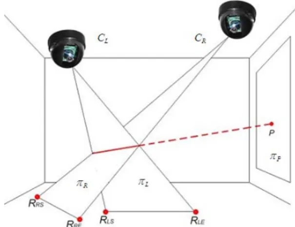
This section describes the configuration of our system and the main idea of our approach. The system uses two cameras mounted on the ceiling, four reference points on the floor, and a projection plane perpendicular to the ground (see Figure 1).
Figure 1. Configuration of the system. In proposed approach, the left and right images are acquired simultaneously from the two cameras. For each of the stereo images, the image pixels of the pointer are obtained through a preprocessing step, and we calculate the best-fit line of these pixels by using principal components analysis (PCA). The line intersects the bounding box of the above image pixels at two points, which are then regarded as (extended) endpoints of the pointer in the image. In this paper, the two sets of pointer endpoints are denoted as {ILS, ILE} and {IRS, IRE}
for the left and right images, respectively.
Once the positions of the above endpoints are located in the left and right images, we use homographic transformation to find their projections, {RLS, RLE} and {RRS, RRE} on the
ground plane. The transformations, HL and HR, are
found in advance by using four reference points marked on the floor (not shown in Figure 1), and their positions in the stereo images. Consider πL,
which is a plane formed by {RLS, RLE} and the
center of left camera CL, and πR, which is a plane
formed with {RRS, RRE} and CR. Planes πL, πR,
and the projection plane πP intersect to form a
point P, the pointing point. Finally, we transform P into the 2D coordinate of the monitor display through another homographic transformation, and the reconstructed pointing position is displayed.
With the above simple reconstruction process, there is no need to find the camera parameters, as required in some 3D reconstruction approaches, and we can operate our pointing system correctly under the real-time condition. However, there are some noises in the imaging process which cause reconstruction errors, making the pointing position not stable. To that end, an efficient error analysis approach for estimating system errors is proposed, as presented next.
3. Error Analysis
For the real world implementation of the pointing system described above, the reconstructed pointing position (RPP) and actual pointing position are not always the same. Such discrepancies can be categorized into (i) static and (ii) dynamic errors. The error analysis discuss in this section will be focused on (ii) since most of the static ones, which do not change with, time can be corrected by an additional transformation. There are several sources of the errors, and the major one is noises associated with the imaging process. In our system, πP, CL and CR are fixed in
the system, so RPP is decided byπL and πR , and
in turn, is decided by ILS, ILE, IRS and IRE. During
the extraction of these points from stereo images, the process is often influenced by noises. As a result, the obtained points are not stable, so is the calculated RPP. Thus, we are going to study the deviation of the reconstructed points due to the variations of ILS, ILE, IRS and IRE.
After some observations, we find that the above noises can cause about ±1 pixels deviation in the images. Therefore, we examine the error in RPP by adding simulated noises to these endpoints (see Figure 2). We first generate 24 simulated points placed evenly (every 15°) a long circles with
187 187.5 188 188.5 189 157 157.5 158 158.5 159 x coordinate (pixe l) y co o rd in a te ( p ixel ) ILS 246 246.5 247 247.5 248 188 188.5 189 189.5 190
x coordinate (pix el)
y co o rd in a te ( p ixel ) ILE 158 158.5 159 159.5 160 141 141.5 142 142.5 143 x coordinate (pixe l) y co o rd in a te ( p ixel ) IRS 225 225.5 226 226.5 227 154 154.5 155 155.5 156
x coordinate (pix el)
y co o rd in a te ( p ixel ) IRE
Figure 2. Four groups of simulated points
radius of 1 pixel, and with ILS, ILE, IRS and IRE as
centers. Thus, we have four groups of the simulated points that correspond to ILS, ILE, IRS and
IRE. After that, in each run of the simulation, four
points each selected from these groups will be regarded as endpoints of the pointer in the stereo images, and used to reconstruct a RPP. In Figure 3(a), red points represent all reconstructed points (RPPs) of simulated points in Figure 2. Furthermore, we pick four of the reconstructed points with maximum (or minimum) X (or Y) coordinates to show the range of reconstruction errors, as shown in Figure 3(b).
In general, it is desirable if such a range can be found more efficiently, e.g., with less simulated endpoints of the pointer. However, a direct reduction in the data size may then reduce the estimated range of reconstruction errors. For example, the blue region in Figure 4 is obtained by using only 4 points from each group in Figure 2.
0 100 200 300 400 500 600 0 50 100 150 200 250 300 350 400 450 x coordina te (pix e l) y c oordi na te ( p ix e l)
Mouse Cursor Position
(a)
(b)
Figure 3. (a) Reconstructed RPPs for simulated points shown in Figure 2. (b) Range of reconstruction errors (with error-free reconstruction show by an “x”).
450 460 470 480 490 500 510 520 530 540 320 330 340 350 360 370 380 390 400 x coordinate (pixel) y co o rd in a te ( p ix el ) Draw Together
Figure 4. Error range shown in Figure. 3 (b) (red), similar range but obtained by using only 4 points from each group in Figure 2 (blue), error range based on internal common tangents (black, see text).
Table 1. Coordinates of the vertices shown in Figure 4.
xmax xmin ymax ymin
(blue) 535.9857 455.9600 395.6483 330.5393 (red) 539.2251 453.4022 397.8248 328.1907 (black) 539.2422 453.2395 397.8823 328.1027 From some close examinations of the relationship between the above reconstruction errors and the locations of individual set of simulated endpoints of the pointer obtained from Figure 2, we found that the error range is mainly due to (two) extreme values in the slopes of
LE LSI
I (and IRSIRE ). Based on such an
observation, we then try to use only two points from each circle shown in Figure 2, which corresponded to the internal common tangents of the two circles shown in each of the stereo images. The range of reconstruction error thus obtained is also shown in Figure 4 (in black). One can see that such a result is almost overlapped with that obtained using all (24) points from each group of simulated points shown in Figure 2. A more in depth examination of this phenomenon can be carried out by comparing the coordinates of the vertices shown in Figure 4, as listed in Table 1. Thus, by using only the contacts of the internal common tangents of the two circles in each image, the number of simulated points can be reduced greatly.
(a) (b)
(c)
Figure 5. (a) Left image. (b) Right image. (c) Estimated error range and actual RPPs.
According to the above observations, we know that the determination of a RPP of a pointer from stereo images will get more errors if it is rotated (than if it is translated) accidentally due to noise in the images. On the other hand, we can estimate the maximal reconstructed errors by using the contacts of the above internal common tangents and improve the system accuracy based on such error analysis.
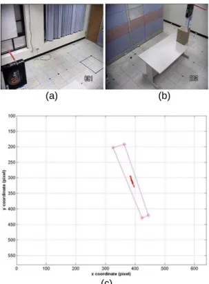
4. Experiments
In the experiments, we fixed the pointer in the space and estimated the errors in the reconstructed RPPs. In Figures 5(a) and (b), the orange stick is used as a pointer which is fixed in the workspace. In Figure 5(c), the pink rectangle shows the estimated range of reconstruction errors, while the red dots are the actual positions of reconstructed RPPs. One can see that the latter is well bounded by the former. Figures 6 (a) to (c) show results similar to those depicted in Figure 5, but with a different pointer location. One can see that in this case, the actual errors and estimated errors are similar. In Figure 6(c), the locations of the RPPs are now distributed in a fairly narrow region, which is predicted very well by the estimated range of errors.
Thus, with the proposed analysis approach, the distributions of RPPs due to imaging noise can be estimated reasonably for (i) different pointer locations, and (ii) different set of stereo images obtained from different pairs cameras. In other words, our approach can be used to find the way to reduce the pointing error if the pointer is allowed to use in different locations, and if there are more than one pair of cameras that can be used in the pointing system under consideration.
(a) (b)
(c)
Figure 6. (a) Left image. (b) Right image. (c) Estimated error range and actual RPPs
5. Conclusions
An efficient error analysis method is achieved by estimating the worst-case error ranges, affected by image noises. When using the similar pointing systems, analysis results can indicate a suitable operation position. Moreover, in a multi-camera environment the system can automatically choose a suitable pair of cameras that can get a more accurate result.
References
[1] Rahul Sukthankar, Robert G. Stockton and Matthew D. Mullin, “Smarter Presentations: Exploiting Homography in Camera-Projector Systems,” Proceedings of International
Conference on Computer Vision, pp.
247-253, 2001.
[2] Jean-François Lapointe and Guy Godin, “On-Screen Laser Spot Detection for Large Display Interaction,” Proceedings of the
IEEE International Workshop on Haptic Audio Environments and their Applications
(HAVE), pp. 72-76, 2005.
[3] Dominic Laberge and Jean-François Lapointe, “An Auto-Calibrated Laser-Pointing Interface for Collaborative Environments,” Proceedings of the VSMM
2003 – Ninth International Conference on Virtual Systems and Multimedia, pp.
501-508, 2003.
[4] Antonis A. Argyros and Manolis I.A. Lourakis, “Vision-based Interpretation of Hand Gestures for Remote Control of a Computer Mouse,” Proceedings of the
HCI’06 workshop (in conjunction with ECCV’06), LNCS 3979, pp. 40-51, 2006.
[5] SHIN SATO and SHIGEYUKI SAKANE,
“Interactive hand pointer that projects a mark in the real work space,” Transactions
of the Institute of Electrical Engineers of Japan, Vol. 121-C, No. 9, pp. 1464-1470,
2001.
[6] Yi-Ping Hung, Yao-Strong Yang,
Yong-Sheng Chen, Ing-Bor Hsieh and Chiou-Shann Fuh, "Free-Hand Pointer by Use of an Active Stereo Vision System,"
Proceedings of 14th International Conference on Pattern Recognition, pp.
1244-1246, 1998.
[7] Eiichi HOSOYA, Hidenori SATO, Mild KITABATA, Ikuo HARADA, Hisao NOJIMA and Akira ONOZAWA, “Arm-Pointer: 3D Pointing Interface for Real-World Interaction,” Processings of the
European Conference on Computer Vision Workshop on Human Computer Interaction,
pp. 72-82, 2004.
[8] Ji-Gao Hsu, “An Implement of a Rel-time Human Computer Interaction Application under Stereo Vision-based Environment,” Master Thesis, National Chiao Tung University, 2006.
[9] Jen-Shing Huang, “Accuracy Analysis of a Stereo Vision-based Pointing System,” Master Thesis, National Chiao Tung University, 2006.
[10] Sergios Theodoridis and Konstantinos Koutroumbas, Pattern Recognition, Elsevier Academic Press, 2003.
[11] Richard Hartley and Andrew Zisserman,
Multiple View Geometry in Computer Vision,
Cambridge University Press, 2003.
[12] David A. Forsyth and Jean Ponce, Computer
Vision A Modern Approach, Prentice Hall,