應用於智慧型機器人系統之嵌入式軟體架構設計與實作
67
0
0
全文
(2) 應用於智慧型機器人系統之嵌入式軟體架構設計與實作 Design and Implementation of an Embedded Software Architecture for Intelligent Robots (ESAIR). 研 究 生:夏恩捷. Student:En-Chieh Hsia. 指導教授:黃育綸 博士. Advisor:Dr. Yu-Lun Huang. 國 立 交 通 大 學. 電機與控制工程學系 碩 士 論 文. A Thesis Submitted to Department of Electrical and Control Engineering College of Electrical Engineering and Computer Science National Chiao Tung University in Partial Fulfillment of the Requirements for the Degree of Master in Electrical and Control Engineering May 2007 Hsinchu, Taiwan, Republic of China. 中華民國九十六年五月.
(3) 應用於智慧型機器人系統之嵌入式軟體架構設計與實作 學生 : 夏恩捷. 指導教授:黃育綸 博士 國立交通大學 電機與控制工程研究所. 摘要 由於缺乏統一的軟硬體規格,機器人系統開發人員常需依據不同的系統規格,重新製 作新系統的軟硬體。為了加速開發時程,並使機器人開發人員能專注於系統中特殊性能 的開發作業,在本論文中,針對嵌入式智慧型機器人系統的特性,以機器人系統內的軟 體元件(components)為主、機器人行為(behaviors)為輔,設計了一套高彈性、可 重複使用的軟體架構。在本論文所提出的智慧型機器人軟體架構(ESAIR)中,主要能 夠提供在分散式機器人環境中,讓機器人系統中的各周邊設備得以透過代理人程式介 面,向機器人控制中心完成設備註冊作業;透過裝置搜尋機制,代理人程式可以找到系 統中驅動其他裝置的軟體物件;透過各裝置所提供的通訊介面,可與外部機器人系統溝 通等。採用ESAIR作為其軟體架構,機器人系統開發人員僅需實作各周邊裝置的驅動程 式、提供相關通訊方法、設定機器人系統的各項行為等,即可完成其軟體系統的初步實 作。此外,本論文中所提之系統架構亦實作一套可隨插即用的軟體元件介面,使各代理 程式可以很容易地視需要卸載/掛載於機器人系統中。此架構已經初步實現於嵌入式智 慧型機器人PAPA-MAN上,在基於開放式原始碼授權之下,目前實作的軟體架構、核心驅 動程式與使用者應用程式等,均已開放給各界使用,期能降低機器人系統開發門檻。. i.
(4) The Design and Implementation of an Embedded Software Architecture for Intelligent Robots (ESAIR) Student: En-Chieh Hsia. Advisor: Dr. Yu-Lun Huang. Department of Electrical and Control Engineering National Chiao-Tung University. Abstract. In this thesis, we propose reusable and flexible software architecture for embedded robot development. The design philosophy of the proposed software architecture is based on the functional components inside the robot system as well as the capabilities and behaviors that can be achieved by the robot. Our work intends to offer a distributed computing environment, an interface for agent programs to register themselves with the control center, a discovery mechanism for agent programs to find and drive their software objects within the same system and a communication interface to talk to other agent programs in different robot systems. The architecture has been designed and implemented as a pluggable component interface so that agent programs can easily hook into the robot system. In addition, under our chosen open-source licensing model, the results, including the implementation of the proposed software architecture together with all the companion kernel drivers and user-land applications, are freely available to the public.. ii.
(5) Acknowledgement First of all, I would like to express my deepest sense of gratitude to my advisor Dr. Yu-Lun Huang for her patient guidance, advice encouragement and excellent advice throughout this study. I would like to thank Dr. Jwu-Sheng Hu and Dr. Kuu-Young Young, for their comments and suggestions for editing of my thesis. I also thank my colleagues in RTES Lab for sharing experiences and knowledge during the time of study. Finally, I take this opportunity to express my profound gratitude to my beloved parents and my friends for their moral support and patience during my study in NCTU.. iii.
(6) Contents. Abstract (Chinese) .......................................................................................................................i Abstract (English).......................................................................................................................ii Acknowledgement .....................................................................................................................iii Contents.....................................................................................................................................iv List of Figures............................................................................................................................vi Chapter 1 Introduction................................................................................................................1 Chapter 2 Related Work..............................................................................................................3 2.1 Player ............................................................................................................................3 2.2 CARMEN .....................................................................................................................4 2.3 CLARAty .....................................................................................................................5 2.4 MARIE .........................................................................................................................6 2.5 OROCOS ......................................................................................................................8 2.6 ORCA .........................................................................................................................10 2.7 MIRO.......................................................................................................................... 11 Chapter 3 ESAIR Overview .....................................................................................................14 3.1 Design Goals ........................................................................................................14 3.2 System Components .............................................................................................15 3.3 Behavior Classification ........................................................................................16 3.4 Software Architecture ...........................................................................................17 3.4.1 Class Definition ...............................................................................................17 3.4.2 Versions of ESAIR...........................................................................................19 Chapter 4 ESAIR Class Overview ...........................................................................................22 4.1 Behavior Supervisor ...................................................................................................22 4.2 Resource Supervisor ...................................................................................................26 4.3 Behavior .....................................................................................................................29 4.4 Reaction......................................................................................................................31 4.5 Sensor Connection......................................................................................................32 4.6 Actuator Connection...................................................................................................35 4.7 Sensor .........................................................................................................................36 4.8 Actuator ......................................................................................................................38 4.9 Summary.....................................................................................................................39 Chapter 5 Implementation ........................................................................................................41 5.1 ESAIR Standard Version Implementation ..................................................................41 5.2 ESAIR Compact Version Implementation..................................................................42 iv.
(7) Chapter 6 Conclusion ...............................................................................................................47 References ................................................................................................................................48 Appendix A...............................................................................................................................51. v.
(8) List of Figures. Figure 2-1 Overall System architecture of Player [6].................................................................4 Figure 2-2 OROCOS framework overview [16] ........................................................................8 Figure 2-3 Relation of Two Orca components[19] .................................................................. 11 Figure 3-1 Relation of system components ..............................................................................15 Figure 3-2 Hybrid Deliberative/Reactive Paradigm.................................................................16 Figure 3-3 ESAIR class inheritance and association diagram..................................................18 Figure 3-4 ESAIR structure of the standard version (STD) .....................................................20 Figure 3-5 ESAIR structure of the compact version (MIN).....................................................20 Figure 4-1 Operation of BS in initialization phase...................................................................22 Figure 4-2 Operation of BS in user control phase ....................................................................23 Figure 4-3 Time sequence diagram of Behavior A sending to Behavior B ..............................24 Figure 4-4 Time sequence diagram of Behavior A receiving from Behavior B .......................25 Figure 4-5 Pseudo code of BS definition .................................................................................26 Figure 4-6 Operation of resource supervisor in behavior registration......................................27 Figure 4-7 Operation of resource supervisor in resource configuration phase.........................28 Figure 4-8 Pseudo code of RS definition .................................................................................29 Figure 4-9 Pseudo code of Behavior definition........................................................................31 Figure 4-10 Pseudo code of Reaction definition ......................................................................32 Figure 4-11 Relation of sensor connection...............................................................................33 Figure 4-12 Interaction in the process of behavior receiving data from sensors......................34 Figure 4-13 Pseudo code of SC definition ...............................................................................35 Figure 4-14 Pseudo code of AC definition ...............................................................................36 Figure 4-15 Relation of Sensor class in ESAIR STD...............................................................37 Figure 4-16 Pseudo code of Sensor definition .........................................................................38 Figure 4-17 Pseudo code of Actuator definition.......................................................................39 Figure 5-1 Hardware architecture of STARFISH.....................................................................42 Figure 5-2 PAPA-MAN ............................................................................................................43 Figure 5-3 Hardware architecture of PAPA-MAN ...................................................................43 Figure 5-4 Software Implementation of PAPA-MAN ..............................................................44 Figure 5-5 PAPA-MAN software architecture without ESAIR MIN .......................................45 Figure 5-6 PAPA-MAN software architecture with ESAIR MIN ............................................46 Figure A-1 Method of WriteData..............................................................................................53 Figure A-2 Method of ReadData ..............................................................................................53 Figure A-3 ISR_SynMotor method ..........................................................................................54 vi.
(9) Figure A-4 PCCommandDecode method .................................................................................57 Figure A-5 The main() in PAPA-MAN.....................................................................................58. vii.
(10) Chapter 1 Introduction. Advances in robot technology have enabled even greater implementation complexity for various kinds of robots. From one point of view, a robot can be defined as an automation process involving different kinds of hardware and software components working in harmony. Those components are usually tightly coupled to allow a systematic design from the outset. However, due to the lack of uniform hardware and software specifications, for every new system, robot developers must re-design the hardware platform and the software architecture, especially for embedded cases where both software and hardware budgets are limited. In this thesis, we attempt to address this issue, and we thus propose an embedded software architecture for intelligent robots (ESAIR for short) based on the design patterns in software engineering. Designing mobile robot system is a tedious task because it is first of all complex – each robot system coordinates several I/O peripherals, performs complex behaviors and manipulates sophisticated operations – and also because it is diverse – different robot systems are equipped with different hardware resources, perform various behaviors and run various applications. The complexity and diversity make the design of robot systems relatively difficult and result in a long development cycle. In addition, the rapid growth of robotics applications has led developers to introduce a variety of resources to meet diverse requirements. To shorten the development processes, software engineering is widely adopted for designing robot systems. Recently, many researchers have proposed various software architectures for developing their robot systems. Among them are CARMEN (The Carnegie Mellon Robot Navigation Toolkit)[1], Player[2][3][4][5][6], CLARAty (Coupled Layer Architecture for Robotic 1.
(11) Autonomy)[7][8][9],. MARIE. (Mobile. and. Autonomous. Robotics. Integration. Environment)[10][11], MIRO (Middleware for Robotics)[12], OROCOS (Open Robot Control Software)[13][14][15], SmartSoft[17], ORCA[18][19] and RT-Middleware[20][21]. Based on component-based software engineering, most of them provide a framework for robot systems that has reusability, flexibility, modularity and distribution. While all this research provides several frameworks to solve development problems in robotic software modules, most of these frameworks do not address their implementation in embedded systems. Additionally, it is difficult to implement most of the above frameworks in embedded systems with limited hardware resources, such as 8-bit microcontrollers or 32-bit non-MMU microcontrollers. Consideration of embedded systems is important in designing a mobile robot system, especially one which performs sophisticated actions in addition to basic locomotion. With an embedded design, it is possible to make the mobile robot system more compact and more energy-efficient. In this thesis, a robotic software framework designed for embedded systems is proposed to provide high reusability, flexibility, modularity and distribution. With the proposed framework, it will be easier to customize specific software modules for individual robot systems. The remainder of this thesis is organized as follows. Chapter 2 discusses related work in the area of robotic software. Chapter 3 presents the proposed software architecture for intelligent robots (ESAIR) and explains why it is useful. Chapter 4 presents the design details and implementation modes of the classes in ESAIR. Chapter 5 presents an implementation of ESAIR on a bipedal robot system. Chapter 6 concludes the ESAIR project and outlines the future work we want to do.. 2.
(12) Chapter 2 Related Work. In the past few years, many researchers have contributed to developments of the robotic software framework. The framework is based on component-oriented software engineering, and among the desired attributes are reusability, flexibility, modularity and distribution.. 2.1 Player In 2001, the Player/Stage project presented a mechanism that enabled effective data flow among sensors, processors and actuators and that worked on single robots, in groups and across the Internet. The project proposed a device server that provides a flexible interface to access a variety of sensors and actuators. Player is a device server that provides a powerful, flexible interface to a variety of sensors and actuators (e.g., robots). Because Player uses a TCP socket-based client/server model, robot control programs can be written in any programming language and can be executed on any computer with network connectivity to the robot. In addition, Player supports multiple concurrent client connections to devices, creating new possibilities for distributed and collaborative sensing and control. Its features include the following: z. Player is designed to be language and platform independent.. z. Player makes no assumptions about how you might want to structure your robot control programs.. z. Player allows multiple devices to present the same interface.. z. Player is designed to support virtually any number of clients.. z. The behavior of the server itself can be configured on the fly.. 3.
(13) Figure 2-1: Overall System architecture of Player [6]. The overall system architecture of Player is shown in Figure 2-1. In the center portion of the figure is player itself. On the left are the physical devices, and on the right are the clients. Each client has a socket connection to Player. At the other end, Player connects to each device by whatever method is appropriate for that device. The Player/Stage project was initially implemented on the Pioneer Robot, but it is still being refined. It currently boasts a large user community around the world in academic, industrial and government labs. As of October 2006, Player/Stage had logged over 60,000 downloads and many current active developers such as USC, Stanford, U. Mass, and U. Penn.. 2.2 CARMEN In 2003, M. Montemerlo et al. designed modular software, dubbed CARMEN, to control mobile robots. The software provides basic navigation primitives, including base and sensor control, logging, obstacle avoidance, localization, path planning, and mapping. It also eases 4.
(14) the implementation of new algorithms on real and simulated robots. It adopts IPC (Inter Process Communication) along with TDL (Task Description Language), which were developed by R. Simmons et al. at CMU, to handle the interconnection between tasks in the robot system. The approximate three-tier architecture provided by CARMEN includes a base layer to handle hardware interaction and control, a navigation layer to implement navigation primitives, and a third tier reserved for user-level tasks that employ primitives from the second tier. CARMEN’s core functions are: z. Carmen is modular robot control software.. z. Carmen uses the inter-process communication platform IPC.. z. Process monitoring.. z. Robot hardware support for different platforms. z. Robot/sensor simulator (in 2d). z. Message logging and playback functionality. z. Centralized parameter server. z. Carmen is written in C, but provides Java support.. z. Carmen runs under Linux and is available under GPL.. A set of core CARMEN modules is isolated to provide a simple set of navigation primitives; these primitives (base control, localization, tracking, and path planning) should serve as a strong foundation for building higher-level robot capabilities. Many existing robot software packages tend to bundle multiple features into single modules. CARMEN’s approach is to tightly constrain the number of features in the core modules, requiring additional features to be implemented in higher layers. Providing a small set of core functionality addresses all of our stated design goals, in that simple modules are typically easier to understand, and are more easily made reliable. Tracking down bugs becomes increasingly time-consuming for developers as the size of the modules (and the size of distributions) balloon. Large software distributions can also be overwhelming for developers and users alike.. 2.3 CLARAty CLARAty, sponsored by NASA since 2001, is a uniform and reusable robotic software 5.
(15) framework. It simplifies the development and integration of new technologies on robot systems. CLARAty is a domain-specific robotic architecture designed with four main objectives: (i) to reduce the need to develop custom robotic infrastructure for every research effort, (ii) to simplify the integration of new technologies onto existing systems, (iii) to tightly couple declarative and procedural-based algorithms, and (iv) to operate a number of heterogeneous rovers with different physical capabilities and hardware architectures. The CLARAty architecture has two distinct layers: the Functional Layer and the Decision Layer. The Functional Layer uses object-oriented system decomposition and employs a number of known design patterns to achieve reusable and extendible components. These components define an interface and provide basic system functionality that can be adapted to a variety of real or simulated robots. It provides both low- and mid-level autonomy capabilities. The Decision Layer couples the planning and execution system. It globally reasons about the intended goals, system resources, and state of the system and its environment. The Decision Layer uses a declarative-based model while the Functional Layer uses a procedural-based model. Because the Functional Layer provides an adaptation of a physical or simulated system, all specific model information is collocated in the system adaptations. The Decision layer receives this information by querying the Functional Layer for predicted resource usage, state updates, and model information. However, additional adaptation-specific heuristics are often used with current planners to assist in plan generation. These adaptation-specific heuristics, which are only used by the Decision Layer, can be accessed directly and not via the Functional Layer.. 2.4 MARIE MARIE, proposed by C. Cote et al. in 2004, is an open source software project that uses a component-based approach to build a robotic software framework that can integrate existing. 6.
(16) and new software components. It has three-tier architecture and employs a component mediation approach to realize the integration of heterogeneous software components. MARIE’s software architecture addresses the following requirements: Component Mediation Approach, Layered Architecture and Communication Protocol Abstraction.. 2.4.1 Component Mediation Approach To implement distributed applications using heterogeneous components, MARIE adapted the Mediator Design Pattern to create a Mediator Interoperability Layer (MIL). The Mediator Design Pattern creates a centralized control unit (the Mediator) which independently interacts with each colleague (referred to as components), and coordinates global interactions between colleagues to achieve the desired system.. 2.4.2 Layered Architecture Supporting multiple sets of concepts and abstractions can be achieved in different ways. MARIE does so with layered software architecture, defining different levels of abstraction into the global middleware framework. Three abstraction layers are used to reduce the amount of knowledge, expertise and time required to use the overall system. It is up to the developer to select the most appropriate layer when adding elements to the system. The Core Layer consists of tools that communicate, handle data, distribute computing, and operate low-level system functions (e.g. memory, threads and processes, I/O control). The Component Layer specifies and implements useful frameworks to add components and to support domain-specific concepts. The Application Layer contains useful tools to build and manage integrated applications using available components to craft robotic systems.. 2.4.3 Communication Protocol Abstraction Component functions can often be used without any concern for the communication protocols, as they are typically designed to apply operations and algorithms on data, 7.
(17) independently of how data are received or sent. This improves components’ interoperability and reusability by avoiding the need to fix the communication protocol during the component design phase. Ideally, this choice should be made as late as possible, depending of which components need to be interconnected. For this reason, a communication abstraction framework, called Port, is provided for communication protocols and component interconnections.. 2.5 OROCOS In 2001, the OROCOS project aimed to develop a generic modular framework for robot and machine control. Robotics is a very broad field, and many roboticists are pursuing quite different goals, dealing with different levels of complexity, real-time control constraints, application areas, user interaction, etc. Since the robotics community is not homogeneous, OROCOS targeted four categories of developers which are shown in Figure 2-2.. Figure 2-2: OROCOS framework overview [16]. 2.5.1 Framework Builders These developers do not work on any specific robotics application, but they provide the infrastructure code to support applications. This level of supporting code is often neglected in. 8.
(18) robot software projects, because in the (rather limited) scope of each individual project, putting a lot of effort in a generic support platform is often considered to be “overkill;” sometimes it is not taken into consideration at all. However, because of the large scope of the OROCOS project, the Framework gets a lot of attention. The hope was, of course, that this work would pay of by facilitating developments for other “Users”.. 2.5.2 Component Builders These developers implement basic robotics functions, that work on top of the generic Framework. These functionalities are offered as a “service”, in the form of a (Software) Component. Such a component is not (necessarily) a full application in itself, but the Component Builders do their best to provide high-quality functionality, in an application-independent way. That is, the programming interface for the robotics functionality is rich and well documented, and the component can be used as a stand-alone part in various applications. Most components come in one of three different types. The simplest is an object-oriented class hierarchy, which offers direct access to the object’s data and functionality. A medium-level component provides monitored access to the object’s functionality, in the sense that it guarantees that different accesses do not interfere with each other, and that the object always remains in a consistent state. The highest-level component has the properties described in the CORBA Component Model.. 2.5.3 Application Builders These developers use the OROCOS Framework and Components, and integrate them into one particular application. That means that they add a specific, application-dependent architecture and API on top of the functionalities offered by the Framework and the Components. One example of an OROCOS application is the OROCOS Control Kernel, which provides an application framework for control, with a set of components which 9.
(19) implement control or planning algorithms.. 2.5.4 System Builder These researchers use the products of Application Builders to program and run their particular tasks. The focus of the OROCOS project lies primarily on the Framework Builders and the Component Builders. Since all contributors are motivated by their own particular applications, the needs of the Application Builders are also taken into account, albeit indirectly. End Users are not one of OROCOS’ target audiences because OROCOS concentrates on the common framework, independent of any application architecture. Serving the needs of the End Users is left to Application Builders.. 2.6 ORCA ORCA is an open-source framework to develop component-based robotic systems. It provides the means for defining and developing the building-blocks which can be pieced together to form arbitrarily complex robotic systems, from single vehicles to distributed sensor networks. To implement a distributed component-based system, one must be able to define interfaces and choose a communication mechanism. In the case where cross-platform operation involves different operating systems, the software which provides such functionality is typically referred to as middleware. ORCA’s selected middleware is the Internet Communications Engine (ICE) which is a modern proprietary implementation of middleware ideas, similar in spirit to CORBA. Figure 2-3 shows an example of two Orca components written in different languages and running on two different operating systems. The communication between these two components is handled by ICE. The main goal of ORCA is continued progress in robotic research and the robotics industry. The main challenge at present is the complexity and sheer quantity of software 10.
(20) specific to robots. Software reuse promises a solution to both of these problems. The features of ORCA are: z. Adopts a Component-Based Software Engineering approach without applying any additional architectural constraints. z. Uses a commercial open-source library for communication and interface definition. z. Provides tools to simplify component development, but makes them strictly optional to maintain full access to the underlying communication engine and services. z. Uses cross-platform development tools.. Figure 2-3: Relation of Two Orca components[19]. 2.7 MIRO MIRO is a distributed object-oriented framework for mobile robot control, based on CORBA (Common Object Request Broker Architecture) technology. The MIRO core components have been developed in C++ for Linux. Due to its programming language independence, further components can be written in any language and on any platform that provides CORBA implementations. 11.
(21) The MIRO core components have been developed with the aid of ACE (Adaptive Communications. Environment),. an. object-oriented,. multi-platform. framework. for. OS-independent inter-process, network connection and real-time communication. They use TAO (The ACE ORB) as their ORB (Object Request Broker). TAO is designed as a high-performance implementer of real -time applications. Therefore MIRO should be easily portable to any other OS where ACE and TAO run. These include many Unix clones, Windows NT and some real-time operating systems. MIRO was built because existing robot control architectures were not sufficient to fill the needs of usability, reliability, scalability and portability. The hardware devices (sensors and actuators) run concurrently, and, due to the constant lack of computing power, tend to reside on multiple computers. When the goal of cooperative behavior among multiple autonomous robots becomes of interest, this system as a whole will become well-distributed. MIRO uses ACE and TAO because they are multi-platform, high-performance libraries which proved to be very sophisticated in terms of usability, portability and scalability.. 12.
(22) Table 1: Comparison of related projects Player/Stage. CARMEN. CLARAty. MARIE. MIRO. ORCA. OROCOS. Framework. Y. Y. Y. Y. Y. Y. Y. Component. X. X. X. Y. Y. Y. X. API. Y. X. X. X. X. X. Y. Distribution. Y. Y. Y. Y. Y. Y. Y. Modularity. Y. Y. Y. Y. Y. Y. Y. Layer. N. N. 2. 3. 3. N. N. Real-time guarantee. N. N. Partial. Y (by ACE). Y(by ACE). N. Y(by ACE). Interaction. Client/Server. IPC. Client/Server. Mediator. CORBA. CORBA. Mediator. Reusability. (layer) Flexibility. Y. Y. Y. Y. Y. Y. Y. Robustness. X. Y. X. X. X. X. X. Middleware. N. N. N. ACE. ACE+TAO. ICE. ACE+TAO. (ORCA2). (S). (POSIX+TCP) Open Source. Y. Y. N. Y. Y. Y. Y. Simulator. Y. Y. N. Y. N. Y. N. (Stage). (Stage or CRAMEN) Software Resource. Library. Core +. X. Component. Core +. Core +. Library. Component. Component. +Component. +interface.. 13. Library.
(23) Chapter 3 ESAIR Overview. The design of software architecture for robot systems should take into account not only the components that comprise the system, but also the behaviors that describe the coordination among components. This chapter introduces the proposed software architecture ESAIR and explains the design goals, the behavior classification and the design details of ESAIR’s component-based approach.. 3.1 Design Goals The major goal of the proposed software architecture is to provide higher flexibility, better reusability and ease of manageability for software components.. z. Flexibility Although the concept of middleware is not considered in this design, flexibility with. ports should be maintained to accommodate different hardware and software platforms. z. Reusability Reusability is the likelihood a segment of source code can be used again to add new. functionality with little or no modification. The reusable software components should also eliminate hardware and software restrictions to be independent from platforms. z. Manageability Manageability means that it should be easy to manage software plug-ins. We would like. to design manageable components that can be inserted and removed in runtime without disturbing the current execution of robot systems. Manageability reduces the complexities in device connectivity and improves scalability of robot systems.. 14.
(24) 3.2 System Components Generally, robot software frameworks are either component-based or behavior-based. Component-based software frameworks make robot systems in which it is easy to insert and remove components. Behavior-based frameworks provide a friendly interface to define behaviors or operations in a robot system. ESAIR combines concepts of both approaches. In the proposed architecture, new behaviors can be easily defined to coordinate system components.. Similar to a computer. system, the components for a robot system fall into four categories: control units, sensors, actuators and communication modules. These are shown in Figure 3-1. The control unit acts as a central processing unit (CPU) in a PC system; it handles the algorithms and coordinates other system components to perform a specific behavior. Sensors can be treated as input devices that obtain data, such as environmental information, an object’s location, velocity, and so on. Actuators are output peripherals that perform real commands from the control units. The communication module is similar to the bus system; it handles the information exchanged among the system components in a robot. These system components make the robot system work well and perform various behaviors and operations.. Figure 3-1: Relation of system components. 15.
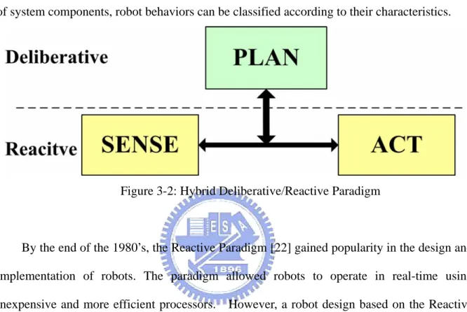
(25) 3.3 Behavior Classification Behaviors, the core of robot systems, represent coordination and interaction among the system components, sensors, actuators, and controller mentioned in the previous chapter. Since the coordination or interaction may or may not depend on the previous or current states of system components, robot behaviors can be classified according to their characteristics.. Figure 3-2: Hybrid Deliberative/Reactive Paradigm. By the end of the 1980’s, the Reactive Paradigm [22] gained popularity in the design and implementation of robots. The paradigm allowed robots to operate in real-time using inexpensive and more efficient processors. However, a robot design based on the Reactive Paradigm could not plan optimal paths, monitor its own performance or select the best behavior to accomplish a task. The sequencing or assembling of behaviors using the Reactive Paradigm relied heavily on the designer. In 1990’s, the Deliberative Paradigm [22] was proposed to provide planning, problem solving and learning capabilities. Upon integrating deliberative plans with the reactive paradigm, a hybrid Deliberative/Reactive Paradigm [22], as shown in Figure 3-2, was proposed to provide good software modularity and allow deliberative functions to execute without being influenced by reactive behaviors. ESAIR adopts the hybrid paradigm and categorizes behaviors as either deliberative or reactive, as shown in Figure 3-2. In ESAIR, deliberative behaviors can actively require information from resources and from other behaviors. It also can memorize and use past. 16.
(26) knowledge to predict future events by applying certain algorithms. The planning of deliberative behaviors allows access to information from/to sensors and actuators in a robot system. On the other hand, reactive behaviors defined in ESAIR can only access specific sensors and actuators according to profiles preconfigured by developers or applications. The reactive behaviors belong to a subset of deliberative behaviors.. 3.4 Software Architecture The software architecture proposed in this thesis consists of a standard version (STD) for robot systems and a compact version (MIN) for embedded platforms with limited resources. This chapter introduces the definition of classes used for building the proposed architecture and the two versions.. 3.4.1 Class Definition In the proposed architecture, ESAIR, four base classes are defined to show an abstract representation of software components in a robot system. The four base classes are the Supervisor class, Action class, Connection class and Resource class. Based on the object-oriented approach, several leaf classes are inherited from these base classes. The four base classes are defined in this chapter, followed by a brief of the inherited leaf classes. First, a Supervisor class responds to the deployment and management of resources and behaviors, such as configuration, device insertion and removals. Generally, a Resource Supervisor class and a Behavior Supervisor class inherit the methods and attributes of the Supervisor class in order to manage the resources and define behaviors, respectively. Second, an Action class defines the activities, including behaviors and reactions, in a robot system. The Behavior class and Reaction class, inherited from the Action class,. 17.
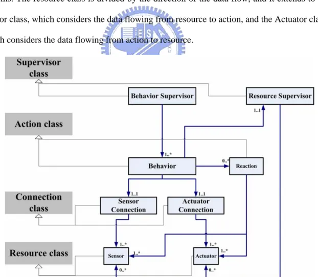
(27) represent the deliberative and reactive behaviors in the hybrid Deliberative/Reactive Paradigm, respectively. The Connection class is designed to bridge the Action class and Resource class and it provides the single entry point between these classes to conceal communication details to heterogeneous devices, while providing a unique simple connection method rather than handling specific connections with a particular device for the Action class. For ease of design, the Connection class is extended to the Sensor Connection class, which only handles data from sensors, and the Actuator Connection class, which only handles connections with actuators. Lastly, the Resource class is comprised of a variety of hardware resources used in robot systems. The resource class is divided by the direction of the data flow, and it extends to the Sensor class, which considers the data flowing from resource to action, and the Actuator class, which considers the data flowing from action to resource.. Figure 3-3: ESAIR class inheritance and association diagram. 18.
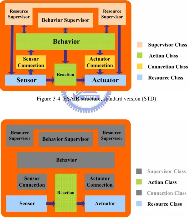
(28) Figure 3-3 illustrates the relationship and inheritance of the four base classes and the eight leaf classes. The classes on the left side shown in gray blocks are base classes, which do not actually exist in ESAIR. They are abstract classes that define the whole software architecture of ESAIR. In other words, ESAIR is comprised of these base classes from an analytical viewpoint. The classes in the right side are the leaf classes inherited from the base classes. The inheritance relationship is shown by the grey lines in the Figure. The control relationship of leaf classes is shown by the arrows. The arrows also note that the number of objects that can be controlled. The composition of those eight classes establishes the basic architecture of ESAIR’s design and implementation.. 3.4.2 Versions of ESAIR According to the hybrid Deliberative/Reactive paradigm, deliberative behavior (hereafter simply the behavior) can be represented by the sequence of reactive behaviors (also called, more simply, reactions). The reactions execute simple operations or make simple decisions. The performance of the entire robot system can be represented by the sequence of behaviors which operate in turns, interact with each other and exchange information. The architectures of most robotic software are composed of a fixed software framework and several behavior modules. The fixed software framework may too large for a robot system with limited hardware resources or for a small robot performing simple applications. For this reason the ESAIR concept is proposed in two versions, the standard version (ESAIR STD) and a compact version (ESAIR MIN). The design allows users to switch between the two versions as needed. The standard version is for a normal robot system which has multi-behavior capabilities and powerful hardware. Figure 3-4 shows the structure of ESAIR STD. It comprises all eight leaf classes and the arrows in the figure show the communication direction between those classes. The Resource Supervisor (RS), Behavior Supervisor (BS), Sensor Connection (SC) 19.
(29) and Action Connection (AC) are the four resident classes that make up ESAIR STD. With this framework, sensors and actuators can be added to the system. In ESAIR STD, the Connection class is adopted to simplify the behavior of sensors and actuators with different communication interfaces. In addition, the Supervisor class can be used to manage these behaviors in a robot system.. Figure 3-4: ESAIR structure, standard version (STD). Figure 3-5: ESAIR structure of the compact version (MIN). 20.
(30) To accommodate systems with limited hardware resources, ESAIR MIN employs just three classes: Sensor, Reaction and Actuator. Removing the Supervisor class and Connection class alleviates the computational load of the robot system, but some flexibility may be sacrificed. Figure 3-5 shows the structure of ESAIR MIN. Because the Supervisor and Connection class are removed, run-time swapping behaviors and resources are not supported. The hardware resources and reactions are selected in advance, during the design stage. In this research, ESAIR STD is implemented in Linux using GPL libraries, and ESAIR MIN is implemented in PIC series MCU using specific libraries. In order to consider the system open-source, the Linux OS was selected for the standard version. Although ESAIR’s goal is to be flexible enough to be used on any kind of platform, ESAIR STD is only compatible with Linux OS and cannot be used on Windows OS. In fact, all open-source projects are based on Linux OS, and so we selected it for ESAIR as well. Furthermore, ESAIR STD can be implemented in two ways. One is that all ESAIR components including RS, BS, AC, SC, Behavior, Reaction, Actuator and Sensor are operated in individual processes and the other is that all these ESAIR STD components in are the threads in single ESAIR STD process. The implementation allows users to switch between two ways as needed.. 21.
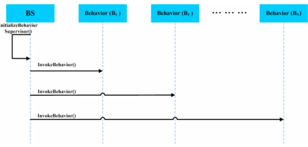
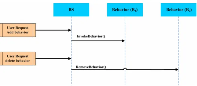
(31) Chapter 4 ESAIR Class Overview. This chapter describes the attributes, operations and responsibilities of the eight leaf classes that comprise ESAIR along with the relationships and interactions between them. There are: Behavior Supervisor class, Resource Supervisor class, Behavior class, Reaction class, Sensor Connection class, Actuator Connection class, Sensor class and Actuator class.. 4.1 Behavior Supervisor The Behavior Supervisor (BS) is designed to deploy the Behavior classes and manage their interconnections. There behavior supervisor defines three processing phases: initialization, user control and interconnection. In first phase, the BS is constructed and invokes the behavior defined in the configuration list. After making the order, the BS enters a WAIT_REQUEST state to wait for requests from users or other behaviors. ESAIR flexibly provides the ability to add and delete behaviors in run-time. Figure 4-1 illustrates the operation of the BS initialization phase.. Figure 4-1: Operation of BS in initialization phase The user controls the second phase, handling the insertion and removal of behaviors with external inputs. When the BS is in the WAIT_REQUEST state (and only then), users can 22.
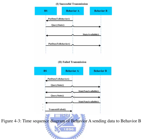
(32) command the BS to add or delete behaviors, which force the BS to enact or ignore the specified behaviors. Figure 4-2 illustrates the operation of the user control phase.. Figure 4-2: Operation of BS in user control phase The third phase is behavior interconnection. The BS acts as a mediator to provide the central unit with the ability to handle the data exchange between behaviors. Adopting the mediator design pattern simplifies this exchange because it monitors only each behavior’s connection with the BS and does not need to consider peer-to-peer connections between behaviors. This approach enables initiating and removing behaviors during run-time. This phase deals with two types of interconnection. The first arises when a target behavior wants to send data to a selected behavior, and the other is when a target behavior wants to receive data from a selected behavior. In the first situation, the target behavior sends data directly to the BS, which hands the data transmission to the selected behavior. Before sending the data, however, the BS queries and checks the state of the selected behavior to determine whether it is able to receive the data. If so, the BS sends the data along to the selected behavior and notifies the target behavior of the successful transmission.. The upper part of Figure 4-3 shows the time sequence of a successful. data transmission, and the arrows show the interaction among those components.. 23.
(33) Figure 4-3: Time sequence diagram of Behavior A sending data to Behavior B. If the selected behavior is not-available to receive data, the BS repeats the query until the status changes or until a fixed time interval elapses. If it still cannot send data to the selected behavior at the end of the time interval, the BS cancels the sending order and notifies the target behavior with a fail message. The lower part of Figure 4-3 is shows the time sequence in a failed transmission situation. When a target behavior wants to receive data from a selected behavior (the second situation in the BS’ third phase), the BS receives the request and queries the selected behavior to determine if it can send the data. If the selected behavior is available to send data to the target behavior, the BS orders the data, receives it from the selected behavior and sends it on to the target behavior to complete the task. The upper part of Figure 4-4 illustrates the interaction among these components in a successful data transmission.. 24.
(34) Figure 4-4: Time sequence diagram of Behavior A receiving from Behavior B. If at the end of a fixed time interval the BS has not received a positive response to its query from the selected behavior, it cancels the order and sends a fail message notifying the target behavior. The lower part of Figure 4-4 shows the components’ interaction in this scenario. In the behavior interconnection phase, ESAIR does not employ typical mechanisms such as a mediator or observer design pattern because those mechanisms are updated automatically with information from the components. Automatically updating information for every behavior is a processor-intensive task however, and it requires powerful hardware support. To lighten the processing load of behavior interconnections, ESAIR adopts a mechanism that sends and receives data according to the requests from behaviors. The pseudo code of the class defining the BS is shown in Figure 4-5.. 25.
(35) Class BehaviorSupervisor () { public: BehaviorSupervisor (char* BehaviorList); ~BehaviorSupervisor(); PutDataToBehavior(char* behavior, char* data); GetDataFromBehavior(char* behavior); QueryBehaviorState(char* behavior); HMICommand(char* behavior); // … private: InitializeBS(); InvokeBehavior(char* behavior); RemoveBehavior(char* behavior); //… }. Figure 4-5: Pseudo code of Behavior Supervisor. 4.2 Resource Supervisor The Resource Supervisor (RS) serves two functions. It deploys Resource classes and handles requests from behaviors to configure those resources. The RS achieves these results using a four-phase process. The first two phases, initialization and user control, are very similar to the first two phases of BS. The difference is that the deploying targets are not behaviors, but resources. RS initializes all the pre-defined resources in the first phase and receives users’ requests to add/remove resources in the second phase. The user control phase is similar to the one in BS. Here, the user can add or remove resources, and RS receives and handles those requests in the Sensor Connection and the Actuator Connection. Because users are assigned the highest priority, they can delete a resource directly, without any allowance.. 26.
(36) The third phase is the behavior registration phase. Before a behavior can use a resource, it needs to register a request with the RS. The resource registration mechanism stores information about behaviors’ resource usage for both the RS and the Connection. Furthermore, the developer also can pre-define the allowed usage of every resource and provide levels of resource usage authority using the registration mechanism. After a behavior registers with the accessed resource, the registration messages are checked by RS in the resource configuration phase and inspected by the sensor/actuator connection before the behavior uses or configures the resource. The data structure of resource registration information is used to share data between the RS and Connection classes. Figure 4-6 shows the operation between the behavior and RS in the behavior registration phase. After the registration is completed, the behavior receives acknowledgement from the RS, and it can then connect to the registered resource using the Connection. Further details of the interaction among behaviors, Connections and resources will be discussed in parts 4.5 and 4.6 of this thesis.. Figure 4-6: Operation of resource supervisor in behavior registration. The fourth phase is the resource configuration phase. This phase handles requests from behaviors to configure the attributes of resources. The behavior only can configure a resource after registering with the RS in the third phase. The configuration mechanism is based on the operation of the ioctl function in the I/O sub-system of a UNIX-like operating system. This 27.
(37) phase is the primary function of RS. The connection of resources is kept separate from the data flow and the control flow. The main goal of RS is to isolate the control flow of the Resource class. The data flow of resources is handled by Connections. The mechanism that separates the flow of control instructions from the flow of data simplifies the implementation and makes ESAIR reusable and flexible. Figure 4-7 shows the interaction of a behavior attempting to configure the Sensor class using the RS. RS will check the registration of resources and authenticate usage permission, before allowing the behavior to use the resource. The pseudo code of the class definition of RS is shown in Figure 4-8.. Figure 4-7: Operation of resource supervisor in resource configuration phase. Class ResourceSupervisor () { public: ResourceSupervisor (char* ResourceList); ~ ResourceSupervisor(); HMICommand(char* behavior); RegisterBehavior(char* behavior, char* resource); ConfigureResource(char* behavior, char* resource);. 28.
(38) CheckRegistration(char* behavior, char* resource); // … private: InitializeRS(); InvokeResource(char* resource); RemoveResource (char*resource); //… }. Figure 4-8: Pseudo code of RS definition. 4.3 Behavior A behavior class is an independent software component in ESAIR. Because behaviors are processed individually, the system guarantees reusability and ease of use and management. Every single Behavior class provides a single sophisticated capability, such as face recognition, path tracking and so on. The definition of the behavior follow is deliberative in the hybrid deliberative/reactive paradigm approach. Behaviors can be smoothly added or removed by the BS to allow developers to achieve ideal robot performance. Behavior classes include three parts, or methods, which are outlined below. First a behavior defines itself with primitive abilities that outline the initializing, terminating and executing of the behavior. Those primitive abilities form the life cycle of the behavior. The initialization of the behavior happens in the first or second phase in the BS. During the execution of the behavior, it may need to communicate with other behaviors or resources to get the required information to assist in the targeted task. Terminating a behavior can be done manually in the BS user control phase, or it can self-terminate if the behavior specifies a one-time task and not an infinite loop task. Second, communication with other behaviors is handled by the BS. The behavior may send data to other behaviors, receiving data from other behaviors, and query the current state of another behavior. When sending data to another behavior, the BS handles the transaction. 29.
(39) Receiving data from involves a request to the BS, which sets out to acquire the data from the selected behavior. The BS’s ability to query the current state of the selected behavior is important for determining whether data can be sent to or received from the selected behavior. Successful data transmission, for send and receive requests alike, is not guaranteed if the selected behavior is unavailable, and the target behavior is notified of any failure. The non-guaranty of data transmission ensures the independence of each single behavior, though it sacrifices ties between coupled behaviors. Although communications between behaviors are not guaranteed, ESAIR is provides an adjustable time out interval to increase the likelihood of successful data transmission, and thus increases the robustness of the system. Third a behavior may require communication between resources. The methods employed here include registering a resource, attaching resources, detaching resources, obtaining data from sensors, sending data to actuators and configuring resources. Registering and configuring resources are responsibilities of the RS. After the behavior registers with the selected resource, the behavior will attach to the resource using the Connection. Then the behavior can send data to actuators and receive data from sensors. The pseudo code of the definition of a Behavior class is described in Figure 4-9.. Class Behavior () { public: Behavior(); ~ Behavior(); BehaviorState(); //query state from BS PutData(); //receiving data from BS AckMessage(); //receiving acknowledge from BS or RS UpdateData(); //receiving updating data from SC // … private: Initialize();. 30.
(40) Active(); CommunicateResource(); //communicate with resources by Connection CommunicateBehavior(); //communicate with behavior by BS Terminate(); //… }. Figure 4-9: Pseudo code of Behavior definition. 4.4 Reaction In ESAIR, a Reaction class is a sub-set of the Behavior class. It is adopted by the reaction part of the hybrid deliberative/reactive paradigm. To introduce the concept of the Reaction class, it will be discussed here in the context of the two ESAIR versions. In ESAIR STD, the Reaction class can be regarded as the resident or primitive behavior needed in almost every robot system. A reaction can interact with resources without using the Connection class. This means that behaviors that need an immediate response can be chosen for implementation by the Reaction class. Furthermore, because a reaction is limited by the usage of resources and a pre-defined stopping point, reactions only govern simple behaviors. Reactions are a sub-set of the Behavior class, so they can be regarded as a limited version of the Behavior class. In contrast to the Behavior class, the Reaction class only has three parts: main functional capability (primitive), the communication with resources and the communication with Behavior classes. The main functional capabilities of reactions are identical to those of behaviors. In the Reaction class, communication with resources is direct rather than mediated by the Connection class. The developers need to select swappable methods to realize the connection of resources to reactions when off-line. When a reaction communicates with a Behavior class, it only needs to receive the request from the behavior and operate those commands, which could include disabling the reaction. 31.
(41) In. ESAIR. MIN,. the. Reaction. class. is. either. platform-dependent. part. or. platform-independent. Platform-dependent reactions consider communication with resources using several communication interfaces on different platforms. Developers can select a suitable interface for their target resources. To combine these communication interfaces, the shell of the reaction is constructed. Platform-independent reactions provide the core of an operation algorithm and decision-maker for a reaction. Independent reactions control dependent resources to perform the desired reaction. The pseudo code of the definition of Reaction class is described in Figure 4-10.. Class Reaction () { public: Reaction(); ~ Reaction(); Disable(); //can be disabled by Behavior // … private: Initialize(); Active(); Communicate(); //communicate with sensors or actuators Terminate(); //… }. Figure 4-10: Pseudo code of Reaction definition. 4.5 Sensor Connection In ESAIR, the Communication class between behaviors and resources isolates them from each other. The existence of the Connection allows behaviors and resources to easily swap because the relationships among those components are simple and fixed (A behavior class. 32.
(42) relates to the BS and the Connection and Resource class relate only to the connection class). Sensor connection (SC) is one leaf of the Connection class, and it handles data transmission to and from sensors in the robot system.. Figure 4: Relation of sensor connection. The SC works like a router to designate the path from specific sensors to designated behaviors. It handles all data collected by the sensors in the robot system and the control connection is handled by the RS. The relation among behaviors, sensors and the SC is shown in Figure 4-11. SC is one of the resident components in ESAIR STD. In run-time, SC receives data from all sensors in the robot system, but those data are not recorded unless they are requested by the behaviors. The sensor data will not be saved if the data is not required for a behavior, but the receiving process from every sensor in the sensor connection is continuous. After a behavior registers a sensor from the RS, the RS will update the register information to the SC and the Behavior class will attach to a specific sensor from the SC. The behavior requests the attachment of a sensor, and SC will route the required sensor data information to the behavior. After the behavior attaches to that sensor through the SC, the 33.
(43) behavior can receive the required sensor data, updated automatically by the SC. The interaction among the behavior, RS and SC is illustrated in Figure 4-12.. Figure 5: Interaction when a behavior receives data from sensors. The data transferred from sensors to the SC can be categorized by the type of data update: periodic updating and event-triggered updating. Periodic updating is done by sensors set up to transfer data to the SC in fixed time intervals. This is often used for sensors that gather environmental information such as temperature, pressure and so on. Event-triggered updating comes from sensors such as buttons, keypads or touch panels which update data when certain events are triggered. This type of sensor can interact with users, and the data gathered is triggered by users or certain defined events. Figure 20 shows periodic updating between sensors and SC. Because the SC handles the data collected by sensors, the control collisions will not arise. SC supports various Behavior classes that require the same sensor data. The pseudo code of the definition of SC is described in Figure 4-13.. 34.
(44) Class SensorConnection () { public: SensorConnection(char* ResoureList); ~ SensorConnection(); RScontrol(); //using by RS handle resource data flow AttachSensor(char* behavior, char* resource); //attach by behavior GetData(char* behavior, char* resource); //call by behavior to get sensor data UpdateData(char* resource, char* data); // … private: InitializeSC(); Active(); InvokeResource(); RemoveRsource(); //… }. Figure 4-13: Pseudo code of SC definition. 4.6 Actuator Connection The Actuator Connection (AC) is similar in format to the SC. The only difference between these two Connection classes is that AC receives commands from behaviors and routes them to a specific actuator. The mechanism that attaches an actuator to a behavior registration is same as in the SC. The main function of the AC is to designate actuators when ordered by behaviors. In ESAIR, many behaviors can control the same actuator, but this could entail logic conflicts (e.g. one behavior commands the actuator to speed up but another behavior commands the same actuator to slow down). ESAIR provides no solution for this conflict – nor should it. The behavior developer needs must reconcile this situation. The AC does not supply a coordination mechanism for actuator connection because ESAIR is a general robot software. 35.
(45) architecture, and a robot’s design detail falls outside its purview. The AC needs no decision-making or coordination mechanism – it simply selects the route by which a behavior can access a desired actuator.. Moreover, AC does not include memory. It can only route. commands to actuators as it receives them. Without coordination consideration, the design of AC is quite simple. The pseudo code of the definition of AC is described in Figure 4-14. Class ActuatorConnection () { public: ActuatorConnection(char* ResoureList); ~ ActuatorConnection(); RScontrol(); //using by RS handle resource data flow AttachActuator (char* behavior, char* resource); //attach by behavior SendComm (char* behavior, char* resource); //call by behavior to get sensor data // … private: InitializeSC(); Active(); UpdateComm(char* resource); InvokeResource(); RemoveRsource(); //… }. Figure 4-14: Pseudo code of AC definition. 4.7 Sensor The sensor class is one leaf class of the resource class. In ESAIR, the Sensor class has different functions in ESAIR STD and ESAIR MIN. In ESAIR STD, because the robot system includes the operating system, the control operation of the Sensor class is provided by the drivers. The Sensor class in ESAIR STD is based on the OS driver, which designs the shell to connect to SC through the ESAIR-defined. 36.
(46) interface. In other words, the Sensor class is the ESAIR agent that handles the OS driver and interacts with the resource supervisor and the sensor connection. The Sensor class is needed to achieve run-time adding/deleting of sensor usage and to support dynamic configurations from different behaviors. The Sensor class is the agent of the sensor driver in the OS to provide more flexibility for operations in ESAIR. The Sensor class comprises two parts: control related methods and data transmission methods. The controls come from the RS. The data transmission methods are handled by data updates (either periodic or event-trigger) to the SC. Figure 4-15 shows the relationships among the Sensor class, robot system, SC and RS.. Figure 4-15: Relations of the Sensor class in ESAIR STD. In ESAIR MIN, the Sensor class is redesigned to accommodate a robot system that has no operating system. The Sensor class here is not an agent of the sensor driver. Instead it replaces the driver in the operating system. The Sensor class in CPT provides basic control and implements data transmission. Because the embedded processors may use simple sensor devices such as a pressure sensor and an infrared sensor, the functions of the Sensor class can be simple and encapsulated in the library for reuse. The Sensor class in ESAIR MIN is. 37.
(47) platform-dependent. The robot developer must select a platform and use the correct sensor component to assemble ESAIR MIN.. The pseudo code of the definition of sensor is. described in Figure 4-16.. Class Sensor() { public: Sensor(); ~ Sensor(); SCcontrol(); //receive command from SC PeriodicUpdateData(); //update data to SC periodically EventUpdateData(); //update data to SC by event-triggered //.. private: InitializeSensor (); Configure(); ReceiveData(); //receive data from sensor //… }. Figure 4-16: Pseudo code of Sensor definition. 4.8 Actuator The Actuator class is another leaf class of the Resource class. Just like the Sensor class, the Actuator class exits in both ESAIR STD and ESAIR MIN, though it plays a different role in the different versions of ESAIR. In ESAIR STD, the Actuator class is an agent of the actuator driver that makes the actuator driver dynamically attach to AC and RS. Like the Sensor class, the Actuator class connects connect with RS and AC using either commands or data transmission. In fact, the only significant difference between the Sensor class and the Actuator class ESAIR STD is the. 38.
(48) direction of data transmissions to the Connection classes. In ESAIR MIN, the Actuator class is not just an agent; it also controls the operation of the physical actuator. The Actuator class in ESAIR MIN is a reusable component providing the basic operations of actuators. It is platform-dependent and the developer needs to select the platform before using those resource components. After choosing the platform and selecting the needed resource components, the developer can use the interface of the Resource class to develop the desired behavior. The pseudo code of the definition of actuator is described in Figure 4-17. Class Actuator () { public: Actuator(); ~ Actuator(); ACcontrol(); //receive command from AC ReceiveCommand(); //receive command from AC //.. private: InitializeActuator (); Configure(); UpdateCommand(); //update command to actuator //… }. Figure 4-17: Pseudo code of Actuator definition. 4.9 Summary To sum up the ESAIR classes, the Behavior class and Reaction class are designed to show enable the performance of the robot system. These two classes are where designers can implement their new algorithms or applications. Moreover, the resource-related classes, the Sensor class and the Actuator class, are 39.
(49) incorporated as hardware in the robotic system. By using existing drivers and following the basic control rules of resource usage, robot developers can configure the robotic platform easily and pay more attention to design behaviors and reactions. To make managing resources and behaviors easier, the BS and RS are provided in the standard version of ESAIR to manage the addition/deletion of behaviors and resources, data exchange and resource configuration. The BS and RS are resident components in ESAIR STD, but they are not included in ESAIR MIN because they require greater hardware capabilities. Additionally, smaller systems require less control over behaviors and resources. The Connection class acts as a mediator. With this class ESAIR STD enables easily swappable software components among Behavior classes, Sensor classes and Actuator classes. The Connection class centralizes the management of connections between behaviors and resources.. 40.
(50) Chapter 5 Implementation The proposed ESAIR architecture was implemented on a mobile robot platform with two mechanisms: . ESAIR STD was implemented on an omni-directional wheel robot, and ESAIR MIN was implemented on a bipedal robot.. 5.1 ESAIR Standard Version Implementation The wheel robot is named STARFISH. The ARM core in TI OMAP 5912 is used as the central controller for the robot system. Various sensors and actuators are installed on the platform. Two 8-bit microcontrollers are used to control and process these sensors and actuators. They are connected via I2C and communicate with the CPU through RS232 interface. In addition, a USB wireless card is installed on the platform to communicate with remote control center (PC), as shown in Figure 5-1. These sensors and actuators, including microphone, digital camera, optical flow sensors and omni-directional wheel motors, are the physical devices presented in the physical layer. In the local robot platform, sensor classes and actuator classes are implemented to configure and control these physical devices. There are three Behavior classes and one Reaction class implemented on the STARFISH platform. The first behavior is to receive audio data and determine the source of the audio. The second is set to drive the wheel motors, rotate the robot toward the sound source and instruct the digital camera to take a picture. Because the computation is complex, the first two behavior classes are processed remotely. The last one is to move around according to the default path. In addition, the reaction class is to determine a new path to reconnect to the remote. 41.
(51) control center and move toward the last location while the wireless connection is stable. When the wireless connection is stable, the robot system performs a sequence of operations: moving around a default path, receiving audio data, calculating and determining the location of the sound source, rotating the robot toward the audio source and taking a picture. These behaviors can be used in home surveillance and security patrolling. If a local robot system fails to connect to the remote control center, however, the robot system will continue to move around as it tries to reconnect to the remote control center.. Figure 5-1: Hardware architecture of STARFISH. 5.2 ESAIR Compact Version Implementation The bipedal robot is named PAPA-MAN (shown in Figure 5-2). Figure 5-3 shows its hardware architecture. The PAPA-MAN architecture can be divided into three parts: central control board, actuator control board and sensor control board. PIC18F452 is used as the central controller in those three boards. The actuator control board processes an operation received from the central control board and sends instructions to all servo motors on the robot system. The sensor control board receives data from pressure sensors and sends those data to 42.
(52) the central control board. The central control board has two functions: receiving information from the sensor control board and the remote control center and sending operational data to the actuator control board.. \ Figure 5-2: PAPA-MAN. Figure 5-3: Hardware architecture of PAPA-MAN. The software architecture of PAPA-MAN adopts ESAIR MIN, which is built in to its mechanism. The Human-Machine Interface is inside the remote center. 43.
(53) PAPA-MAN has several functions including auto-balancing, standing up, sitting down, prostrating and dancing. Auto-balancing is a reaction built in to PAPA-MAN. When its balance is disturbed, the abnormality will be detected by pressure sensors and sent to the central control board. The other four operations are performed by instructions sent from the remote control center. Those operations may be initialized by the behaviors or by the developer with the Human-Machine Interface.. Figure 5-4: Software Implementation of PAPA-MAN. As PAPA-MAN has no remote control center, ESAIR MIN has been implemented. Autobalancing and the received operations from the remote control center are categorized as reaction classes. The reaction classes exist in the MCU of the central control board. The sensor class and the actuator class communicate with the central control board. The sensor class is built into the MCU of the sensor control board and the actuator class is built into the MCU of the actuator control board. Figure 5-4 shows the implementation of ESAIR MIN in PAPA-MAN. As compared with Figure 3-5, the three classes of ESAIR MIN are built into the software of PAPA-MAN. Nevertheless, because of the usage limitation of the MCU, the 44.
(54) software realization of those classes is implemented by the basic functions’ API. The reaction class comprises its four main functions: receiving information from the sensor class, receiving information from the remote control center, sending operation instructions to the actuator class and making decisions based on existing reactions. The actuator class and sensor class include two main functions: managing the hardware resource and communicating with the central control board.. Figure 5-5: PAPA-MAN software architecture without ESAIR MIN. Without ESAIR, the software architecture of PAPA-MAN embodies a normal sequential programming architecture, shown in Figure 5-5. The program is based on a main loop that passes on received commands from the remote center to operate sub-operations. The sub-operations are the pre-defined PAPA-MAN operations such as standing up and sitting down. Those operations decode the outside commands and send a specific sequence of actuator controls, which are stored in the memory, to the actuators’ control boards. Using ESAIR MIN in PAPA-MAN redesigns the software architecture to achieve a new 45.
(55) modularity, ease of maintenance, and ease in adding new operations. The PAPA-MAN software architecture with ESAIR MIN is shown Figure 5-6. Figure 5-6 illustrates the Reaction class in PAPA-MAN’s central control board, and the code block A, B, C in Figure 5-6 is identical to the blocks in Figure 5-5. Using an object-oriented approach to redesign the program can increase the flexibility, and make it easier to maintain and add new sub-operations.. Figure 5-6: PAPA-MAN software architecture with ESAIR MIN. 46.
(56) Chapter 6 Conclusion. In this thesis, we proposed embedded software architecture for intelligent robots (ESAIR) and implemented it on the mobile robot systems STARFISH and PAPA-MAN. With ESAIR, the devices and the corresponding software modules can be easily inserted and removed from the robot system without redesigning the architecture. In addition, two different versions of ESAIR have been created, ESAIR STD and ESAIR MIN, to accommodate various robot system platforms. ESAIR marks the beginning of research toward the goal of a general and uniform architecture that suits various hardware platforms and accommodates all sensors and actuators. The experimental results show that with this architecture in place, developers can concentrate on implementing robotic behaviors instead of working out the control codes used to drive physical devices. It is obvious that the ESAIR is useful in developing highly robust embedded robot systems. Our work will continue as we attempt to coordinate multiple robots performing complex behaviors. Under our chosen open-source licensing model, the proposed ESAIR software architecture is open to the public, along with all its companion device drivers and user-land applications.. 47.
數據
![Figure 2-1: Overall System architecture of Player [6]](https://thumb-ap.123doks.com/thumbv2/9libinfo/8467869.183414/13.892.204.740.127.527/figure-overall-system-architecture-of-player.webp)
![Figure 2-2: OROCOS framework overview [16]](https://thumb-ap.123doks.com/thumbv2/9libinfo/8467869.183414/17.892.155.791.529.929/figure-orocos-framework-overview.webp)
![Figure 2-3: Relation of Two Orca components[19]](https://thumb-ap.123doks.com/thumbv2/9libinfo/8467869.183414/20.892.248.707.446.794/figure-relation-of-two-orca-components.webp)

+7
相關文件
After the desired content has been identified, the control point needs to determine which transfer protocol and data format should be used to transfer the content from the
當事人 出納組 會計室 人事室.
Two causes of overfitting are noise and excessive d VC. So if both are relatively ‘under control’, the risk of overfitting is smaller... Hazard of Overfitting The Role of Noise and
n Media Gateway Control Protocol Architecture and Requirements.
Regardless of terminal or network logins, the file descriptors 0, 1, 2 of a login shell is connected to a terminal device or a pseudo- terminal device. Login does
Step 5: Receive the mining item list from control processor, then according to the mining item list and PFP-Tree’s method to exchange data to each CPs. Step 6: According the
Through the enforcement of information security management, policies, and regulations, this study uses RBAC (Role-Based Access Control) as the model to focus on different
Then, these proposed control systems(fuzzy control and fuzzy sliding-mode control) are implemented on an Altera Cyclone III EP3C16 FPGA device.. Finally, the experimental results
