IEEE TRANSACTIONS ON SYSTEMS, MAN, AND CYBERNETICS—PART A: SYSTEMS AND HUMANS, VOL. 31, NO. 3, MAY 2001 223
Modeling Automatic Assembly and Disassembly
Operations for Virtual Manufacturing
Swee M. Mok, Member, IEEE, Chi-haur Wu, and D. T. Lee, Fellow, IEEE
Abstract—A system for evaluating products in their design phase has been developed for virtual manufacturing. It is in-tegrated into a CAD/CAM environment to calculate cost for assembling and disassembling parts. In our earlier work, a generic assembly and disassembly model was developed to represent operations required for product manufacturing and de-manufac-turing. To be useful, the model requires a method for translating high-level instructions from product designers into low-level as-sembly and disasas-sembly instructions. This paper presents a set of rules for accomplishing this task. The developed rules are used for manipulating strings representing parts and handlers in binary assembly and disassembly operations. A telephone assembly and disassembly simulation is used to illustrate the developed system.
Index Terms—Assembly, CAD/CAM, design, disassembly, mod-eling, virtual manufacturing.
I. INTRODUCTION
P
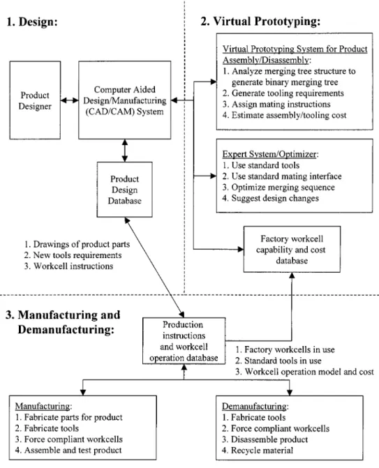
RODUCTS that are difficult to assemble will raise man-ufacturing cost. Moreover, products that are difficult to disassemble will also increase cost in the near future as manufacturers are asked to recycle their products by a more environmentally conscious society [1], [2]. To overcome this potential problem, new products must be designed for easy assembly and disassembly, especially when automation is desired. In our previous work [3], [4], we proposed a solution that integrated a virtual assembly and disassembly (VIRAD) model into a CAD/CAM system. It models the production system as a hierarchical workcell so that product designers can easily evaluate products for manufacturing and de-manufacturing. The system is unique in such a way that it uses a developed part-mating coding system, named structured assembly coding system (SACS) [5], for analysis. The SACS codes can be directly implemented in a force compliant robotic workcell for auto-mated assembly operations. As shown in Fig. 1, products are first designed using a CAD system. In the design process, software tools are used to calculate total assembly and disassembly cost. This feedback enables a designer to identify problematic partsManuscript received January 6, 2000; revised March 19, 2001. This work was supported by the Motorola Center for Telecommunication at Northwestern University. D.T. Lee’s research was supported in part by the National Science Foundation under Grant CCR-9731638, and by the National Science Council under Grant NSC-89-2213-E-001-012. This paper was recommended by Asso-ciate Editor J. Lee.
S. Mok is with the Motorola Advanced Technology Center, Motorola Labs, Motorola Inc., Schaumburg, IL 60196 USA.
C. Wu is with the Department of Electrical and Computer Engineering, North-western University, Evanston, IL 60208 USA (e-mail: [email protected]).
D. T. Lee is with the Institute of Information Science, Academia Sinica, Taipei, Taiwan, R.O.C.
Publisher Item Identifier S 1083-4427(01)04573-8.
and to redesign them as needed so as to minimize total product cost. Finally, the actual manufacturing and de-manufacturing are executed using automated machines modeled by a virtual assembly and disassembly (VIRAD) system.
The system aspect of a VIRAD model is the focus of this paper. We will present our work in defining rules for generating and representing assembly and disassembly operations and components so that a CAD system can be easily linked to a virtual manufacturing system.
II. SYSTEMDESIGN
Accurate modeling and simulation of product assembly and disassembly operations are key features of the proposed VIRAD system. The foundation of VIRAD is a newly developed hier-archical model named the generic assembly and disassembly (GENAD) workcell. It models assembly and disassembly op-erations carried out inside a workcell using a developed struc-tured assembly coding system (SACS) [5], [6], which is briefly described in Appendix A. SACS uses numerical codes to rep-resent a set of well-defined assembly and disassembly proce-dures. By associating each SACS code with its operation cost, a product’s total manufacturing cost can be estimated. Based on SACS codes, a GENAD workcell uses a binary assembly and disassembly tree to represent all assembly and disassembly op-erations and costs. The data generated from a CAD software is used to generate the product’s binary part-merging tree. Key information required will be the principal axis and mating-in-terface’s geometry of all parts. The former is needed for as-sembly task planning while the latter is used for assigning var-ious SACS codes for part-mating operations. A GENAD work-cell is designed to model a workwork-cell environment including its parts, tools, fixtures, and manipulators. All objects in the work-cell are grouped into parts and handlers. Parts are consumable items for making products. Handlers are tools in the workcell for manipulating the parts in order to assemble or disassemble a product. In order to assemble and disassemble parts with han-dlers in the workcell, various operations defined by our SACS codes are used.
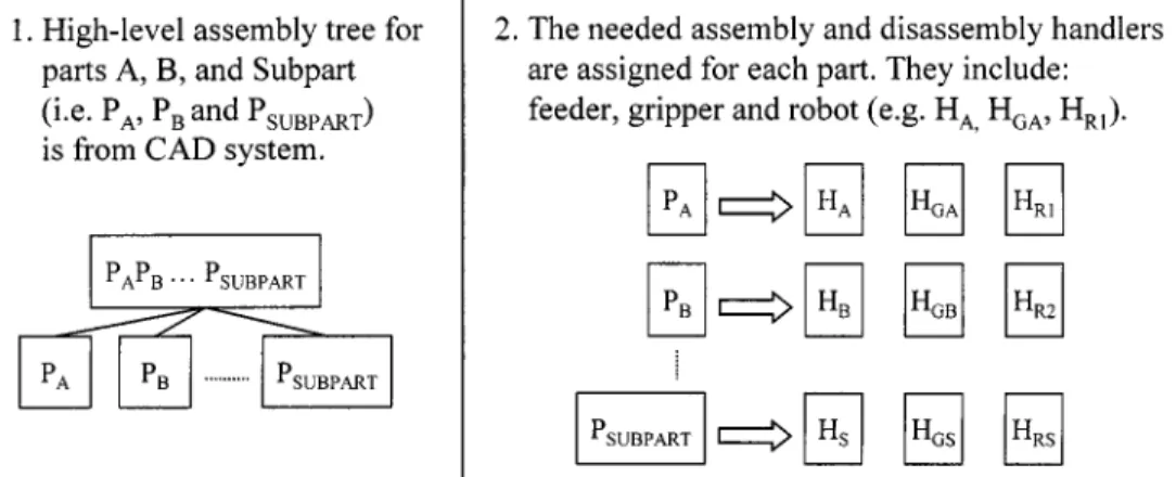
In order to generate an assembly and disassembly tree in a GENAD workcell, a three-step process, as illustrated in Fig. 2, is defined. The first step is to obtain a high-level, assembly tree for the designed product from the CAD system. The product designer can generally provide this tree. The second step is to define various handlers required for executing part-to-part mating operations and then assign these handlers to each part. We will also assign SACS codes for all operations performed by these handlers. The initial assignment is based on a set of standard handlers such as manipulators, part grippers, and
224 IEEE TRANSACTIONS ON SYSTEMS, MAN, AND CYBERNETICS—PART A: SYSTEMS AND HUMANS, VOL. 31, NO. 3, MAY 2001
Fig. 1. Framework of proposed virtual assembly and disassembly for product design.
feeders, as shown in step 2 of Fig. 2. Re-using of handlers such as manipulators and part grippers in a workcell can then be applied to minimize cost. During the third step, assembly instructions for assembling the product will be generated from all part-to-part, handler-to-part, and handler-to-handler operations, as illustrated in step 3 of Fig. 2. Handler-to-handler operations are indirect operations associated with the assembly of a work piece, such as a robot attaching to a part gripper or a feeder being replenished with new parts. Together, these generated instructions form the product’s assembly tree. In addition, each subpart’s tree created from a disassembly operation is an independent binary tree representing operations that can be carried out in a parallel process. In Figs. 2 and 3, these relationships are represented using dotted lines.
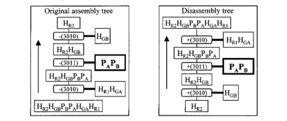
From the assembly tree shown in Fig. 2, we can easily gen-erate a disassembly tree shown in Fig. 3. We first rearrange the binary assembly tree from Fig. 2 in a top-to-bottom direction. For example, the assembly tree’s root node becomes a leaf node
in the disassembly tree. Then, the operators OP1 and OP2 in Fig. 2 are changed from ‘ ’ to ‘ ’ and ‘ ’ to “ ’, respectively. Thirdly, each SACS operator (in the assembly tree) associated with its parent node is now associated with its child node, as shown in part 1 of Fig. 3.
A GENAD workcell uses a small set of SACS-based opera-tions to join primitive parts into larger and more complex parts during assembly, or vice-versa during disassembly. These are the lowest level instructions generated in this process. The rules for handling such operations will be described in the following section.
III. ASSEMBLY ANDDISASSEMBLYOPERATIONS
We shall adopt the following convention to describe assembly and disassembly operations and use strings to represent parts, resulting from these operations.
MOK et al.: MODELING AUTOMATIC ASSEMBLY AND DISASSEMBLY OPERATIONS 225
Fig. 2. Three steps to generate a GENAD tree from CAD data for assembling partsA and B.
Let denote an alphabet set and denote a binary operation, where (symbol : “element of”). Let denote a set of all composite sequences of elements in . Associated with each operator , there is a SACS code, and an associ-ated cost. Moreover, each SACS code involves a stationary part (represented in bold) and a moving part.
A primitive part is denoted by and a composite part re-sulting from a sequence of binary operations is represented by a string , where is a null object. We define string concatenation operation on strings and as
if , and ,
where , and . If
then is defined as . We
further define for any primitive . To assemble two parts and by merging with we write or and represent the resulting part as
. (We assume a stationary composite product represented in bold.) The former assembly notation is known as an infix expression, whereas the latter is known as a postfix
ex-pression. For example, “ ”
means that part is the resulting part of assembly
operation in infix notation, or
in postfix notation.
To disassemble a part by removing a component from a com-posite part, there are two possible operations, and for left and right part removal operations, respectively. If is removed from the left of , we write or
and the resulting two parts are and . If is removed from the right of , we write
or and the resulting parts are also and . In our figures, is treated as the default disassembly oper-ation and it is represented using .
226 IEEE TRANSACTIONS ON SYSTEMS, MAN, AND CYBERNETICS—PART A: SYSTEMS AND HUMANS, VOL. 31, NO. 3, MAY 2001
Fig. 3. GENAD binary tree generated for disassembling partsA and B.
For example, “ ”
means that part is removed from and
the remaining part is represented by , whereas
“ ” will also result
in two composite parts represented by and .
When multiple parts are involved in a sequence of as-sembly and disasas-sembly operations, we may express it using an infix expression, following the conventional eval-uation order of an arithmetic expression involving addition and subtraction operators and parentheses. For instance,
is evaluated as follows.
We can also express the above sequence of operations using a postfix expression, which describes only the operations without explicitly giving the string representations of intermediate
com-ponents. That is, . See [7] for
de-tails of how to evaluate a postfix expression.
In this example, if part was removed first, the resulting part consists of two composite parts represented by and , and a primitive part represented by . We then assemble part with part to get . If now we choose as the sta-tionary part, then by default, becomes the moving object. Consequently, will be placed to the left-hand side of to get a final product of —the reversed representation of . Although these two alphabetical strings look dif-ferent, they still represent the same part in a physical world. As long as the mating interface between and occurs be-tween parts and , they are the same.
MOK et al.: MODELING AUTOMATIC ASSEMBLY AND DISASSEMBLY OPERATIONS 227
In the following we use and to denote a part and dler, respectively, and use subscripts to represent parts’ and han-dler’s names. For example, robot one and a part gripper for a part named are represented by and . They are fur-ther illustrated in Fig. 2, whereby an object is assem-bled from two primitive parts and via an insertion op-eration. They are assembled using two robots, each equipped with a gripper. Robot number one starts by attaching a gripper for part creating . The process is
modeled as . SACS code 3010 is a
posi-tion-controlled assembly operation with a cost c3010 to operate, defined in Fig.8. Robot is modeled by SACS code 3600, a six degrees of freedom (DOF) manipulator. is modeled by SACS code 3110, a one-axis gripper without force compliance, and is stationary during the assembly operation. All the other as-sembly steps in the same figure are self-explanatory following the aforementioned notation.
For the process of disassembling product into part and part , we examine the disassembly tree in part 2 of Fig. 3. The two robots with grippers used in the assembly process are again used to manipulate the parts. At the third level from the bottom of the disassembly tree in Fig. 3, they both grip onto . Following that, a disassembly operation between the in-terface of and takes place. Robot number one with a gripper proceeds to place into a recycling bin before disassembling itself from , representing the part and cycling bin. Similarly, robot two with a gripper proceeds to re-lease part into a recycling bin . Finally, their grippers are returned to their holders at the top most level of the tree, com-pleting the disassembly sequence.
IV. ASSEMBLY ANDDISASSEMBLYCOST
From the generated assembly and disassembly tree, the total assembly and disassembly cost can be formulated as follows: total cost operation cost handler cost.
The operation cost is equal to the sum of all costs associated with SACS operations. Handler cost is the total cost of all han-dlers required for performing the assembly or disassembly oper-ations. For a product that is fully reversible in terms of assembly and disassembly operations, the total cost is obtained by adding all operations as we traverse the assembly and disassembly tree from its leaves to the root. Similarly, total disassembly cost is obtained by traversing the same tree from the root to its leaf nodes. However, if a product that cannot be disassembled by simply applying the assembly operations in reverse or by using the same set of handlers, a different disassembly tree should be generated.
In practice, cost increases with the increased capability of tools; thus, tool selection can significantly influence the final assembly and disassembly cost. In a prototyping environment, handlers’ costs will dominate the total cost. Conversely, opera-tion cost dominates in producopera-tion since it will increase linearly with the number of products made, while handlers’ costs are effectively lowered as they get amortized over a larger number of product units. Maximizing handler reuse is always benefi-cial, especially in low-volume production. In high-volume pro-duction, design should also focus on minimizing operation cost
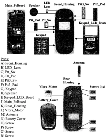
Fig. 4. Telephone with 18 parts used in the simulation.
such as cycle time. At times, it may even make sense to use a higher-cost handler to reduce its operation cost. In the long run, an optimized solution may include a set of standardized GENAD workcells. Then, most parts will be handled by the standard workcells while some custom handlers are used for the remaining (small) set of unique parts.
V. SIMULATIONRESULTS
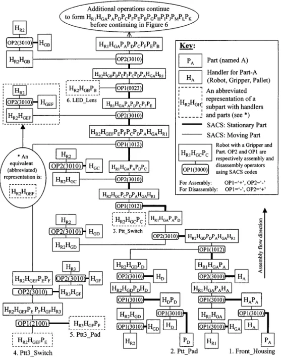
Simulations were carried out on a telephone handset. The product consists of 18 primitive parts, as shown in Fig. 4. Parts and handlers required for assembly and disassembly operations were modeled using the described GENAD workcell method-ology. Each operation for merging and separating parts was as-signed a SACS code, as shown in Figs. 5 –7.
To simplify our simulation explanation, the following abbre-viations were used. First, each part is given an alphabetic name:
through . As before, parts and handlers are denoted as and , respectively. Secondly, the operators named OP1 and OP2 are set to “ ” and “ ”, or to “ ” and “ ”, for assembling or disassembling the product, respectively. Finally, lines con-necting parts and handlers in the assembly tree are coded using two types of line, thicker-line and thin-line, representing the sta-tionary part and moving part, respectively, during assembly or disassembly operation.
As part of our simulation, we used the designer’s telephone assembly tree to generate a detailed assembly and disassembly tree by following the GENAD workcell guidelines. Two key parts named and are important as they hold all the remaining parts in place. Part accepts parts through ,
228 IEEE TRANSACTIONS ON SYSTEMS, MAN, AND CYBERNETICS—PART A: SYSTEMS AND HUMANS, VOL. 31, NO. 3, MAY 2001
Fig. 5. Assembly and disassembly tree generated for the telephone simulation.
while part accepts parts through . Four screws named , and hold the two key parts and together after assembly.
We will now trace their operations as described in the gen-erated assembly and disassembly tree, as shown in Figs. 5–7. The assembly process starts with (Front Housing) and (Ptt Pad), in Fig. 5. They are initially loaded into their respec-tive feeders named and . Once loaded using operator , the resulting “feeder with part ” and “feeder with part ” are denoted “ ” and “ ,” respec-tively. Part grippers for and (abbreviated as and ) are similarly attached to robots one and two (abbreviated
as and ) to form and , as
illus-trated in the lower part of Fig. 5. To assemble parts and moves to the location of . When part is
grasped by , the two objects will merge to become a single object labeled . Before the robot can re-move from feeder , a disassembly operation
separates from . The handler HA is now an empty feeder.
A second robot performs similar operations on , and to form . It then moves to
at-tach itself to , forming .
Robot proceeds to release that is now attached
to . If robot also releases Part
at this point, we would have an assembled part called . However, in Fig. 5, the assembly operation
con-tinues by attaching to to form
. (Notice that robot is being re-used for part after assembling .) When
MOK et al.: MODELING AUTOMATIC ASSEMBLY AND DISASSEMBLY OPERATIONS 229
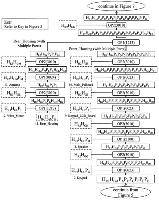
Fig. 6. Generated telephone assembly and disassembly tree continued from Fig. 5.
releases , the three parts are now attached to robot one, represented by . The remaining operations are executed in a similar manner. To reduce clutter in the figures, some detailed operations were not shown explicitly. For example, the LED Lens ( , inside a dotted box) near the top of Fig. 5 has a set of associated part fetching operations that are not shown.
In Fig. 6, four more parts are assembled into the front housing
to form , grasped by .
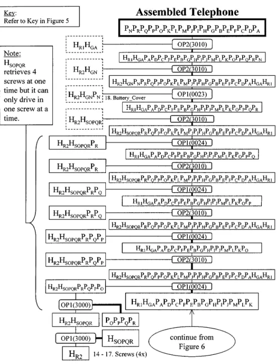
In addition, the antenna and Vibra Motor are assembled into the back housing to form , grasped by . The back housing operations could have been executed in par-allel to the front housing to reduce cycle time if more han-dlers were used. Subsequently, to hold the front and back hous-ings together, a custom handler named drives four screws ( , and ) into the assembled parts. The han-dler can load four screws simultaneously but it dispenses them
one at a time, as shown in the middle of Fig. 7. As a result, the tree has four assembly and disassembly operations using the same handler. Finally, a Battery Cover is assembled to the telephone. The completed telephone is represented by
. For disassembling the telephone, the disassembly tree can be interpreted in a similar fashion. However, the operation starts from a fully assembled product, at the top of the assembly tree. In addition, the operators OP1 and OP2 are now set to “ ” and “ ,” respectively. Initially, an assembly operation creates (robot number one and its gripper). Then, a second set of handlers attaches to the telephone
body and the battery cover . A
dis-assembly operation then separates from the main telephone body . Following that, is placed onto , which is now more appropriately referred to as a recycling bin for .
230 IEEE TRANSACTIONS ON SYSTEMS, MAN, AND CYBERNETICS—PART A: SYSTEMS AND HUMANS, VOL. 31, NO. 3, MAY 2001
Fig. 7. Final part of telephone assembly and disassembly tree ends from Fig. 6.
In this simulation, all parts were considered fully recyclable and they could be disassembled using the same assembly han-dlers. However, most real products have parts that are not de-signed for disassembly. In such cases, the assembly and disas-sembly trees will be different.
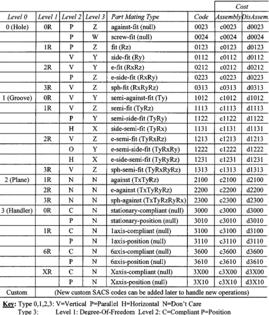
In the assembly and disassembly trees, each SACS code is associated with two operation costs related to assembly and dis-assembly, respectively, shown in Fig. 8 By summing up these individual costs for all SACS operations in a assembly tree, a total cost for product assembly and disassembly can be at-tained. Based on the SACS table defined in Fig. 8, the estimated maximum assembly operation cost for assembling the simulated telephone is equal to
. In this example, SACS operation 3010 was used 47 times for
as-sembling parts and was used 42 times for disasas-sembling parts. In addition, the cost for the required handlers will be
. When OP1 and OP2 are reversed, each assembly operation becomes a disassembly operation and vice-versa. In the simulation, every handler was assumed to be capable of performing both assembly and disassembly opera-tions; thus, the cost of disassembling this telephone can be eval-uated by
. In this case, SACS operation 3010 was used to disassemble parts 47 times and to assemble parts 42 times. In most practical situa-tions, the product assembly and disassembly operations are not
MOK et al.: MODELING AUTOMATIC ASSEMBLY AND DISASSEMBLY OPERATIONS 231
Fig. 8. Assigned SACS codes from the developed structured assembly coding system.
so easily interchangeable. Moreover, handlers are usually de-signed to only perform either assembly or disassembly opera-tions. As a result, their assembly and disassembly operation cost equation will not be the same.
VI. CONCLUSION
A system for assisting product designers to recognize and correct potential manufacturing problems in their product is presented in this paper. The proposed virtual assembly and dis-assembly (VIRAD) system can be integrated into a CAD/CAM environment. It is set up for encouraging product design intervention during the design process so as to prevent badly designed parts from ever reaching production. The developed system uses a model of generic assembly and disassembly (GENAD) workcell, which in turn uses a developed structured assembly coding system (SACS) to describe assembly and disassembly operations.
To illustrate the developed system, a telephone assembly and disassembly simulation was carried out. The results showed that actual assembly and disassembly operations could be modeled successfully. High-level product assembly instruction is first ob-tained from a CAD system. A binary assembly and disassembly tree is then generated. Each part is assigned with a set of han-dlers for assembly and disassembly operations. In our model, we use string notation to manipulate parts and handlers for as-sembly and disasas-sembly. Furthermore, based on cost assigned to each SACS operation, the total cost for assembling or disas-sembling a product can be obtained by summing up the costs required for all SACS operations and handlers.
In our future work, an algorithm for generating optimized GENAD assembly and disassembly trees will be developed. In addition, automatic task planning for assembling and dis-assembling parts based on SACS-defined operations will also be studied. In addition, a muscle-like compliant-control [8], [9] will be implemented on a robot to execute these low-level SACS operations.
232 IEEE TRANSACTIONS ON SYSTEMS, MAN, AND CYBERNETICS—PART A: SYSTEMS AND HUMANS, VOL. 31, NO. 3, MAY 2001
APPENDIX
The previously developed structured assembly coding system (SACS) [5], [6] can encode all mating-operations for assembling two primitive parts in a three-dimensional (3-D) task space. It uses a force compliant system to define assembly operations [8] between a stationary part and a moving part. The geometric constraints between two mating parts, a moving part and a stationary part, are used to determine the assembly or disassembly process. The basic SACS coding system uses four levels (the first four columns in Fig. 8) to code 24 types of part-mating (the fifth column in Fig. 8) operations defined for primitive parts. The corresponding SACS codes for these 24 types are listed in the sixth column of Fig. 8. SACS is a generic coding system based on the geometrical constraints between two parts. A detailed description of how to define SACS codes can be found in [5].
For the purpose of developing a model of GENAD workcell in this paper, a new set of class-3 objects called handlers, such as fixtures, robots, end-effectors, pallets, feeders are also de-fined by the SACS code. For example, the two handlers with SACS codes of 3000 and 3010 are grippers with and without force compliance control, respectively. A Level-0 code of 3 (the first left digit of the SACS code) is always assigned to handlers. Level-1, the second digit of the code, describes the number of degrees-of-freedom (DOF) the handler possesses. A handler with 6R (a Level-1 code of 6) is a robot with six DOF, while a 1R (a Level-1 code of 1) device can be a part conveyor. Level-2 code uses “0” and “1” to represent “ ” and “ ,” corresponding to force compliance and position (no force compliance) control, respectively. The Level-3 code is not currently defined for this group. It can potentially be used for describing special proper-ties such as machine vision fiducial marks.
Finally, each SACS code is associated with a product as-sembly and disasas-sembly cost, as shown in columns 7 and 8 of Fig. 8. Its cost is an object containing a set of information, such as cycle time, tooling cost, and assembly yields.
ACKNOWLEDGMENT
The authors wish to thank I. Turlik, T. Babin, and M. Serrar of Motorola Inc. for their support in virtual manufacturing.
REFERENCES
[1] H. Srinivasan, N. Shyamsundar, and G. Rajit, “A virtual tool to support environmentally conscious product design,” in Proc. IEEE Int. Symp.
Electron. Environment, San Francisco, CA, May 5, 1997, pp. 7–12.
[2] B. H. Lee and I. Kosuke, “Demanufacturing complexity metrics in de-sign for recyclability,” in IEEE Int. Symp. on Electron. Environment, San Francisco, CA, May 5, 1997, pp. 19–24.
[3] S. Mok, C. H. Wu, and D. T. Lee, “A system for automatic assembly and disassembly operations,” in Proc. IEEE Int. Conf. Robotics Automat., vol. 4, San Francisco, CA, Apr. 24–28, 2000, pp. 3695–3700. [4] , “A hierarchical workcell model for intelligent assembly and
dis-assembly,” in Proc. IEEE Int. Symp. Comput. Intell. Robotics Automat., Monterey, CA, Nov. 8–9, 1999, pp. 125–130.
[5] C. H. Wu and M. G. Kim, “Modeling of part-mating strategies for au-tomating assembly operations for robots,” IEEE Trans. Syst., Man,
Cy-bern., vol. 24, pp. 1065–1074, July 1994.
[6] M. G. Kim and C. H. Wu, “A formal part mating model for gener-ating compliance control strategies of assembly operations,” in Proc.
IEEE Int. Conf. Syst., Man, Cybern., Los Angeles, CA, Nov. 1990, pp.
611–616.
[7] A. V. Aho, R. Sethi, and J. D. Ullman, Compilers, Principles,
Tech-niques, and Tools. Reading, MA: Addison-Wesley, 1986.
[8] C. H. Wu, “Compliance control of a robot manipulator based on joint torque servo,” Int. J. Robot. Res., vol. 4–3, pp. 55–71, 1985.
[9] C. H. Wu, K. S. Hwang, and S. L. Chang, “Analysis and implementation of a neuromuscular-like control for robotic compliance,” IEEE Trans.
Contr. Syst. Tecnol., vol. 5, pp. 586–597, Nov. 1997.
Swee M. Mok (M’95) received the B.Sc.(Hon.)
degree in aeronautical and astronautical engineering from Southampton University, Southampton, U.K., in 1985 and the M.S. degree in aerospace engineering from the University of Cincinnati, Cincinnati, OH, in 1987. He is currently pursuing the Ph.D. degree in electrical and computer engineering at Northwestern University, Evanston, IL.
He is a Senior Staff Engineer at Motorola Labs, Schaumburg, IL. He joined Motorola in 1987, where he worked on two-way radio manufacturing. Some of his recent work includes the development of a production process for at-taching fine-pitch flip chips onto organic substrates, high throughput surface mount technology equipment, and wireless biomedical sensors. His current re-search interests include CAD/CAM, assembly and disassembly of electronics products using intelligent force-compliant robots, and embedded devices for control and communication.
Chi-haur Wu received the B.S. degree in electrical
engineering from the National Taiwan University, Taipei, Taiwan, R.O.C. in 1973 and the Ph.D. degree in electrical engineering from Purdue University, West Lafayette, IN, in 1981.
He has been with Department of Electrical and Computer Engineering at Northwestern University, Evanston, IL, since 1983. Before joining North-western, he was with Unimation Robotics Inc., Danbury, CT. During that period, his job involved designing robot motion control algorithms and digital servo systems for PUMA robots and hydraulic-servo Unimate robots. His research interests include engineering design and invention, which includes robotics, human augmentation control, active suspension control, active force absorbing control, vibration isolation, microcontroller and embedded systems, electronic circuit design, sensor-circuit design and control, robotic motion planning and control, compliance and damper control, pattern recognition, integrated industrial automation, automated assembly/disassembly systems, CAD/CAM industrial automation, computer-assisted surgical robot systems, rehabilitation robots, medical images and instrumentations, and remote telemanipulation through Internet and RF.
D. T. Lee (S’75–M’78–SM’84–F’92) received
the B.S. degree in electrical engineering from the National Taiwan University, Taipei, Taiwan, R.O.C. in 1971 and the M.S. and Ph.D. degrees in computer science from the University of Illinois, Urbana-Champaign, in 1976 and 1978, respectively. Prior to joining the Institute of Information Sci-ence, where he is a Distinguished Research Fellow and Director, he was a Professor of the Department of Electrical and Computer Engineering, Northwestern University, Evanston, IL, where he has worked since 1978. From 1989 to 1990, he was the Program Director for the Computer and Computation Theory Program with Division of Computer and Computation Re-search of the National Science Foundation. His reRe-search interests include design and analysis of algorithms, computational geometry, VLSI layout, parallel and distributed computing, web-based computing, algorithm visualization, software tools development, compliant controller for active suspension and vibration con-trol, digital libraries, and advanced IT for intelligent transportation systems. He has published over 120 technical articles in scientific journals and conferences. He is Editor of Algorithmica, Computational Geometry: Theory and
Applica-tions, ACM Journal of Experimental Algorithmics, Chief Editor of the Interna-tional Journal of ComputaInterna-tional Geometry and Applications, Editor-in-Chief of
the Journal of Information Science and Engineering Dr. Lee is a fellow of ACM and a member of IICM.