多核心處理器系統中利用互嵌式技巧之排程方法
多核心處理器系統中利用互嵌式技巧之排程方法
多核心處理器系統中利用互嵌式技巧之排程方法
多核心處理器系統中利用互嵌式技巧之排程方法
A Module-Interlock Technique for Task Scheduling in a
Multi-core Processor System
摘要
摘要
摘要
摘要
在多核心系統平行計算的工作管理上,相依 性與互斥是必須克服的難題。因此在本論文中, 我們提出基於單一非循環圖的互嵌式排程技巧, 用以提昇處理器的使用率,並使得多個非循環圖 的最終執行時間能夠提前。由非循環圖中,我們 乃依關鍵路徑的概念進行排程,以得出甘特圖。 我們設計一個資料結構來將排程中所需的甘特圖 上的資訊紀錄下來,並將此資料結構命名為積 木。根據甘特圖上的處理器需求變化的情形,進 而將積木分為四種型態。判別積木之型態後,可 使適合嵌合的積木數目變少,再依我們所提出技 巧,來進行嵌合的工作,而排程之結果,會使得 處理器的使用率隨著最後執行時間的提前而提 高。 關鍵詞:多核心系統,平行計算,互嵌式排程技巧Abstract
Data dependence and mutual exclusion are problems must be overcome in the task management of multi-core systems for parallel computing. In this paper, we propose a directed acyclic graph (DAG) based task scheduling technique, module-interlock technique (MIT), to keep the processor utilization as high as possible, so as to obtain a shortest execution time. According to the critical path scheme on the DAG, the result of the task scheduling can be presented in a Gantt chart that is then translated into bricks for further scheduling. Bricks in the proposed system are categorized in four types, rectangular, protruding, concave, and uneven, according to the usage of processors. Applying the proposed technique by interlocking proper type of bricks to perform the task re-scheduling, a higher processor utilization with shorter execution time can be achieved.
Keywords: Multi-core system, Parallel computing, Module-Interlock Technique
1. Introduction
While executing tasks are represented by a directed acyclic graph (DAG) [1-4], the critical path concept is commonly used to find out the shortest execution time. Since applied DAG and critical path schemes focus on finding the shortest execution time, the utilization of processors is not always satisfied. Once a task arrives, the system runs the scheme to determine its execution order. In most tasks scheduling schemes, the number of processors needed for the scheduled unit is always the same during the executing period. That is, the processors are occupied by the task until the task is finished. In fact, not all scheduled units need the same amount of processors during the period of execution.
In this paper, we propose a new task scheduling technique, module-interlocking technique (MIT), to keep the processor utilization as high as possible, so as to obtain a shortest execution time without modifying the original scheduling result to obtain the shortest execution time in DAG.
The scheduled unit is considered as a brick. The relations among bricks are independent [5]. Thus, other bricks can not affect their characteristics. The process of the proposed technique is similar to the game of building bricks. In the game of building brick, the objective is to keep the building stable and as high as possible. In order to fully utilize the resources, to reduce the vacant spaces between bricks is important in our approach. In the proposed scheme, the maximum width of bricks is treated as the number of processors in the system and the height of bricks is the time needed to handle all the tasks. If the number of tasks is greater than the number of processors, the optimal solution can be obtained if all processors are always keeping in busy.
李良德
Liang-Teh Lee
大同大學資訊工程系
ltlee@ttu.edu.tw
董維鈞
Wei-Chun Taug
大同大學資訊工程系
wctung@ms29.hinet.net
潘昆祺
Kun-Chi Pan
大同大學資訊工程系
g9506039@ms2.ttu.edu.tw
According to the critical path approach on the DAG, the result of the task scheduling can be presented in a Gantt chart [6] that is then translated into bricks in for further scheduling. Bricks in the system are categorized in four types, rectangular, protruding, concave, and uneven, according to the usage of processors. Fig. 1 shows the scheme of the module-interlock technique. The new brick is sent to the corresponding queue in the brick set, according to the brick type. The proposed technique that uses the shape’s complementary advantage for task scheduling will be discussed in section 3.
Fig. 1: Module-interlock technique scheme In the proposed system, useful metric for performance evaluation is the utilization of processor, and execution time. According to the Gantt Chart of the task scheduling, the effectiveness is measured. By using MIT, the processor utilization can further be improved so as to reduce the execution time.
2. Related Work
According to different goals, various task-scheduling techniques are designed. In order to achieve main objective, the designer may trade in something for accomplishing better performance. For example, in the Earliest Deadline First (EDF) [7,8], it must ensure that tasks should be completed to their deadlines. However, if we are discussing time critical problem in the EDF algorithm, the shortest execution time, the fairness of job execution and the processor utilization are neglected in order to let all jobs finished before their deadlines.
In another example, the Optimal Scheduling algorithm for distributed memory machines is NP-hard complete problem. The critical path approach is similar to the Task Duplication based Scheduling (TDS) algorithm [9-11], which can schedule DAGs with the time complexity of O (n2) for n nodes. And the system has the unlimited processors. It assumed that the numbers of processors are unlimited and
tasks can be duplicated to be executed in different processors.
The critical path scheme is still the best when dealing with the scheduling problem of a single DAG. If the processor usage is always the same for a task in an execution time then it is unreasonable. When we apply the same method on multiple DAG which are scattered and with poor communication, one can not guaranteed the performance. The processor utilization can be very poor. Therefore, we are proposing a new technique, Module-interlock technique, to increase the processor utilization even when it is used in a multiple-DAG situation.
The proposed module-interlock technique can achieve higher processor utilization by taking advantage of the idle time of the processor without changing the scheduling result. We interlock two bricks by the information that is provided in the bricks. We will apply for the static mode scheduling technique. It will be able to promote the utilization of processors and decrease the total execution time.
3. The Module-interlock for the task
scheduling
This section will introduce how to transform the scheduling unit, Gantt chart, into brick form. A brick contains the needed information for scheduling. Furthermore, we will use the transformed brick to perform the scheduling job. The main goal of this activity is to leave no vacant space between bricks. If we look at the activity in the angel of processor utilization, we are actually fulfilling the ability of all processor.
3.1 Brick
The scheduling unit is a Gantt chart in the MIT, and Gantt chart is a scheduling result that is generated by the critical path scheme on the DAG. We designed the brick that collects the necessary information in the Gantt chart in MIT. A Gantt chart can be transformed into a corresponding brick. After the transformation, we can say that the scheduling unit is a brick in MIT. The data structure of a brick is divided into two parts, internal and external, as shown in Fig. 2. The external part is for allocating brick into corresponding queue and the internal part for the interlocking work. The detail of it will be explained in the following subsections.
3.1.1 External data structure
In the external part, it describes the outlook of the Gantt chart, which includes the brick number, length, and type. The number is an integer that records how many bricks in the corresponding queues. The length presents the total execution time of the Gantt chart. Before we explain the function of different type, we will first define the type.
Fig. 3: Four shapes of the MIT
Fig. 3 shows four different types of bricks. They are type A: Rectangular brick, type B: Protruding brick, type C: Concave brick, and type D: Uneven brick. There are two reasons for dividing the bricks into four different types. First, it will be easier to send different type of bricks into the corresponding queue. When we interlock brick, we can easily choose the suitable brick. Second, through the different types we can know the change of the processor utilization of the original scheduling result. The different processor usage variations are expressed in Fig. 4. Four different process usage situations are discussed and it is used to decide which types the Gantt chart should belong to.
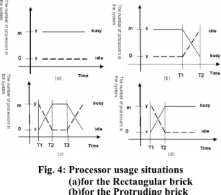
Fig. 4 shows the fundamental situations of processor usage variations. In the graph, the x-axis is the time and y-axis is the number of processors. The total number of processors in the system is m x is the number of busy processors and y denotes the number of idle processors. The relation of m, x, y is y = m –x and T1, T2, T3, and T4 are times that record the variation number of the processors. In Fig. 4 (a), the processor usage is fixed. From the beginning to the end, x is always equal to m. There is no idle processor, i.e., y = 0. This is the best situation for the processor usage. If the situation of process usage in Gantt chart is similar to Fig. 4 (a), the Gantt chart belongs to the type A, Rectangular brick. In Fig. 4 (b), it starts at x= m, all processors are busy until T1. When time is T1, y is not equal to 0 and x keeps going down until T2. We can name this type of brick as Type B, Protruding brick. In Fig. 4 (c), x is the minimum value from T1 to T2 and continues to rise until T2. Form T2 to T3, x
is unchanged and falls from T3 to T4. We call this type of brick is type C, Concave brick. At last, in Fig. 4 (d), x rises form T1 to T2, and equals to m until the job is finished. This type of brick is Type D, Uneven brick.
Fig. 4: Processor usage situations (a)for the Rectangular brick (b)for the Protruding brick (c)for the Concave brick (d)for the Uneven brick
We can easily understand the change of processor’s utilization during execution time by the help of Gantt chart. The change can be translated into graph by plotting the x-axis with time and y-axis with the number of processors. Four fundamental bricks have been presented in Fig. 4. By referencing graphs in Fig. 4, a relative type can be assigned to the Gantt chart. However, there are still some situations that processor usage can not match the fundamental type expressed in Fig. 4.
The following algorithm is used to convert a Gantt chart into a curve, so as to connect to a proper brick type. In the algorithm, i and hi represent the time and
the required processor number in the Gantt chart respectively. The pair (i, hi) repents the hi processors
required at time i, considered as a point in the Gantt chart. In the following algorithm, appropriated points are selected to be connected to a polygon, for matching to a brick type.
Fig. 5: Matching brick type algorithm
Input:
A Gantt chart Output:
A type of Gantt chart Begin
// SP: the number of processors in the system for i = 1 to n
If (hi == SP) then i = target; For t1 = 1 to n
For t2 = 1 to n If ((t2>t1) and (ht1 < ht2))
{If (t1 < target)
Draw a line from (t1, h t1) to (target, h t1);
If (t1 > target)
Draw a line from (t1, h t2) to (t2, h t2);}
Else ((t2>t1) and (ht1 > ht2))
Draw a line from (target, h t1) to (t1, h t1);
Else if ((t2>t1) and (ht1 == ht2) and (ht1 ==SP))
Draw a line from (t1, h t1) to (t2, h t1);
For t = 1 to n
Connecting the height sub line of each time sector To match the types in Fig. 4
In Fig. 6, we list some situations when the processor usage is not matched exactly to the types in Fig. 4. What we do is to record the variation of the processor needed and make the variation to match the types in Fig. 4.
Fig. 6: Non-fundamental types (a)for the Rectangular brick (b)for the Protruding brick (c)for the Concave brick (d)for the Uneven brick
3.1.2 Internal data structure
The internal data structure of brick is for interlocking purpose. It records different time points that contain the index, sub-length and the number of busy processors. For those three columns, the index records changed point in the number of busy processor variation. But, here we must point out that we are only recording the height of the polygon, not all the changes of processors. And the sub-length is the keeping time of the number of busy processors. In the view of the polygon, the sub-length is the width and the number of busy processors is the height. Those values are used to calculate the interlocked saved time and help us to choose the appropriated brick for interlocking.
As an example, Fig. 7 shows an 8-processor situation. The needed processor number arises from time t = 1 to time t = 4 in the Gantt chart. When time t = 4, the needed processor number becomes the maximum. The processor usage number is fall at time t =5 and rises at t = 6. But, in time t = 8, the processor usage number is the same as the value at t = 4. We draw the line from time t = 4 to 8 and make it as the maximum number of processors. From t = 8 to 10, the required processor number is decreasing. The Gantt chart of this example is determined as type C and the total execution time is 10. The internal and external data structures of the Gantt chart are shown in Fig. 7(c) and Fig. 7(d). The type of brick is shown in Fig. 7(b).
Fig. 7: Example of the Gantt chart and the data structure of the brick
(a)Example of the Gantt chart (b)The type C
(c)The internal data structure of the brick (d)The external data structure of the brick
3.2 The brick interlocking algorithm
Interlocking is the process of combining two bricks into a single brick. The advantage of interlocking is that the idle part of the processors of the brick can be shared for interlocked brick. For a certain time point, if the number of processors in the system is enough for two bricks to be executed, we say that the brick is complementary at this time point. By referencing Fig. 4, a better clarity to explain the interlocking type B and type C bricks. For type B brick, in Fig. 4 (b), the processor usage is decreasing from T1 to T2. However, the processor usage of the type C brick is raising form T1 to T2. Thus, the interlocked area can be obtained from combining two bricks type B and type C.By combining two bricks, the total execution time can be reduced and the processor utilization can be promoted. After interlocking type B and type C bricks, we can obtain a new interlocked type B brick. If the interlocked objects are type B and type D bricks, we obtain the interlocked brick shape is the type A. From the view of the graph, the interlocking of brick is complementing and combination of graphs. The pseudo code of interlocking type B and type C bricks is shown in Fig. 8. In Fig. 8, type B and type C bricks are interlocked. We use the tail of type b brick to interlock the head of the type C brick. Since areas of two bricks are not complete, they are interlocked to get the better processor utilization and reduce the execution time. All type B bricks can be chosen to interlock with type C brick. We choose the type B brick with the best processor utilization to interlock with brick C. Of course, to interlock the type B and D bricks can apply the same interlocking procedure with the same reason.
Fig. 8: The interlocking algorithm
3.3 The module-interlock technique
algorithm for the static mode
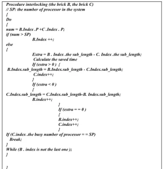
After introducing the two bricks interlock action, how to interlock a group of bricks will be discussed. Fig. 9 presents an algorithm to make every incomplete brick C to interlock with another appropriate brick.
Four different types of bricks are defined previously. The purpose is to provide a convenient way to choose the appropriated brick type for interlocking. The best choice to match the rectangular brick, type A, is the type like itself. Protruding brick, type B, can be interlocked with the brick type C or D. Concave brick, type C, can be execute with type B in the tail and type C or D in the head. Uneven brick, type D, can be combined with the brick type B or C.
Fig. 9: The set interlocking algorithm The time complexity of the interlocking algorithm depends on the length of the internal data structure of the brick. The complexity is O(p2), where p is the length of the brick. Since interlocking set of bricks must perform the interlocking algorithm, for n bricks, the time complexity will be O(n2p2).
The interlocking scheme has been applied in the static mode for simulation. The information of all bricks is known before starting the scheduling. It also means that all external and internal information of bricks are known. The pseudo code of the MIT algorithm is presented in Fig. 10
The module-interlock technique algorithm Input:
Brick sets A, B, C, and D Output:
A schedule Begin
Call the set interlocking algorithm for sets B and C Call the set interlocking algorithm for sets B and D To dispatch the brick A by sequence
End
Fig. 10: The module-interlock technique algorithm
4. Performance measurements
We evaluate the performance of the Module-interlock technique (MIT) for task scheduling in the static mode through simulations. In the module-interlock technique, two useful measuring factors of performance are the total saved execution time and the utilization of all processors. The variables that we concerned are the brick size, the processor number, and the tested brick number for the simulation.
The utilization of all processors is defined as: (total actual execution time of all processors) / (total execution time * processor number) saved time = the execution time with MIT –
the execution time without MIT. Parameters used in the sumualtion are shown in Table 1.
Table 1. Parameters used in the sumualtion
Parameter Explanation
B_num Task number that handle
the system
B_max_size The maximize execute
task size
P_num The processor number of
the system
4.1 Scheduling of practical applications
In this section, we give some examples to illustrate the brick concept. The first example is the analysis of Quick-sort algorithm [12]The number to be sorted is assumed to be 8 and the corresponding data flow chart and Gantt chart can be obtained as shown in Fig. 11. As mentioned before, the Gantt chart is corresponding to the type D brick.
Procedure interlocking (the brick B, the brick C) // SP: the number of processor in the system {
Do {
num = B.Index .P +C .Index . P; if (num > SP)
B.Index ++; else
{
Extra = B . Index .the sub_length - C. Index .the sub_length; Calculate the saved time
If (extra > 0 ) {
B.Index.sub_length = B.Index.sub_length - C.Index.sub_length; C.index++;
} If (extra < 0 ) {
C.Index.sub_length = C.Index.sub_length-B. Index.sub_length;
B.index++; } If (extra = = 0 ) { B.index++; C.index++; }
If (C.index .the busy number of processor = = SP) Break;
}
While (B . index is not the last one ); }
}
The SET interlocking algorithm
The |C| is the total number of the brick C in the corresponding queue */ Input:
Queue B Queue C Output:
B bricks that are interlocked by C bricks Begin
For j =1 to |C|
Interlock all B bricks and the j-th brick C
Select the best processor utilization after interlocking brick B and brick C Modify the B brick
Fig. 11: The brick example of quick-sort Fig. 12 shows the multiplication of two matrices. The matrix multiplication is performed in a 4-processor multi4-processor system, where all operations can be done in parallel and completed in three steps. The steps are shown in Fig. 12(a). Fig. 12(b) is the Gantt chart corresponding to the scheduling result of the steps in Fig. 12(a). By applying the previously method, the Gantt chart in the Fig. 12(b) is corresponding to the brick type A.
Another example is a multiplication of a 2*2 matrix and a 1*2 matrix. There are also 4 processors in the system. The parallel steps of operations in this example are list in Fig. 13(a), and the corresponding Gantt chart can be obtained as shown in Fig. 13(b). Similarly, by applying the previous method, the Gantt chart in the Fig. 13(b) is corresponding to the brick type B.
In Fig. 14, an example of DFS [12,13] is shown. If the number of processors in system is 4, a Gantt chart can be obtained from the DFS by applying the corresponding DAG, as shown in Fig. 14(b). Similarly, by applying the previously method, the Gantt chart is corresponding to the brick type C as shown in the Fig. 14(c).
Fig. 12: The example of matrix multiplication
Fig. 13: The example of matrix multiply
Fig. 14: The brick example of DFS
4.2 The simulation result
Fig. 15 shows the relation between the number of tested bricks and the processor utilization. We found that the utilization of the processor depends on the number of bricks. When the processor number is relatively large, the brick types B, C, and D have more opportunities to obtain the better interlocking performance. The processor utilization with MIT is always better than that with FIFO. Although the curves of MIT and FIFO in Fig. 15 are not increasing monotonically, the difference between MIT and non-MIT is always positive.
Fig. 15: The utilization of processor with respect to brick size and brick number
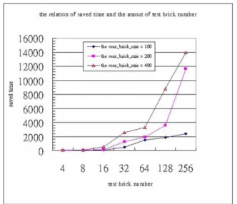
Fig. 16 shows the relation of brick size and the saved time. When increasing the number of tested bricks, the processor utilization is going better as shown in Fig. 15, and the saved time is increased accordingly. The number of tested bricks and the brick size can be adjusted in the simulation. The brick size is set to 100, 200, and 400. The degree of the saved time depends on the brick size. When the brick size is increased, the test brick’s length in the simulation is enlarged, and the degree of idle processor is also increased. If the degree of idle processor is large, then it is easy for a brick to obtain the interlocked brick, so as to improve the processor utilization. Thus, when the brick size is bigger, the saved time is increased extensively in the simulation.
Fig. 16: The relation of the saved time and the interlocked brick number.
Fig. 15 and Fig. 16 show that the proposed method is practicable. The processor utilization is improved by MIT, and the total execution time is reduced.
5. Conclusion
Finding the smallest execution time is the main goal of the critical path scheme illustrated in a DAG. There is no doubt that the critical path idea is the best method for finding the shortest execution time in the DAG. But, on the condition like critical path scheme the utilization of process is not considered. As we can see, the reduction of the total execution time always leads to poor processor utilization. In order to keep up the processor utilization and reduce the total execution time at the same time, a new scheduling technique, module-interlocking technique, has been presented.
In this paper, tasks are plotted on the Gantt chart and transformed into the predefined type of bricks. When the module-interlocking technique is applied on the tasks, the original scheduling result is not altered at all. By using the idle processor in the brick, we can interlock different bricks together to increase the processor utilization, so as to reduce the total execution time, and the original scheduling result is not altered. The proposed method is simple and is proved that the method is profitable in the simulation.
6. References
[1] Henan Zhao and Rizos Sakellariou, “scheduling Multiple DAGs onto Heterogeneous Systems,” International Parallel and Distributed Processing Symposium (IPDPS 2006), April 2006.
[2] Ligang He, Stephen A. Jarvis, Daniel P. Spooner, Graham R. Nudd, “Performance Evaluation of Scheduling Applications with DAG Topologies on Multiclusters with Independent Local Schedulers.” IEEE International on Parallel and Distributed processing Symposium, April 2006.
[3] Sang Cheol Kim, Sunggu Lee, Jaegyoon Hahm, “Push-Pull:Deterministic Search-Based DAG Scheduling for Heterogeneous Cluster.” IEEE Transactions on Parallel and Distributed Systems, VOL 18, Issue 11,Page(s):1489-1502,2007.
[4] Rashmi Bajaj, Dharma P. Agrawal, “Improving scheduling of tasks in a heterogeneous environment.” IEEE Transactions on Parallel and Distributed Systems, VOL 15, Issue 2,Page(s):107-118, Feb 2004.
[5] Huiyang Zhou, “A case for fault tolerance and performance enhancement using chip multi-processors.” IEEE Computer Architecture Letters, VOL 5, Issue 1, Page(s):22 – 25, Jan.-June 2006.
[6] Abraham Silberschatz, Peter Baer Galvin, Greg Gagne, "Operating System Concepts, 7/e, John Wiley, 2004.
[7] Theodore P. Baker, “An analysis of EDF Schedulability on a Multiprocessor,” IEEE Transactions on Parallel and Distributed Systems, VOL16, NO. 8, AUGUST 2005. [8] Prasad Calyam, Chang-Gun Lee, Phani Kumar
Arava, Dima Krymskiy, “Enhanced EDF scheduling algorithms for orchestrating network-wide active measurements,” IEEE International Real-Time Systems Symposium, 2005.
[9] Liang-Teh Lee, Chin-Hsiian Liang, and Hung-Yuan Chang, “An Adaptive Task Scheduling System for Grid Computing.” IEEE International Conference on Computer and Information Technology, Sept. 2006.
[10] Kun He, Yong Zhao, “A New Task Duplication Based Multitask Scheduling Method,” Proceedings of the Fifth International Conference on Grid and Cooperative Computing (GCC’06), Page(s):221 – 227, Oct. 2006.
[11] Sekhar Darbha, Dharma P. Agrawal, “Optimal Scheduling Algorithm for Distributed-Memory Machines, “ IEEE Transactions on Parallel and Distributed Systems, vol. 9, No. 1, January 1998.
[12] Ellis Horowitz, Sartaj Sahni, Dinesh Mehta, Fundamentals of Data Structures in C++, 2/e, Silicon Press, 2006.
[13] Thomas H. Cormen, Charles E. Leiserson., Introduction to algorithms, 2/e, MIT, 2001.