一個改進無線網路服務品質之代理人機制
65
0
0
全文
(2) 一個改進無線網路服務品質之代理人機制 An Agent-based System for Improving Quality of Service. over Wireless Networks 研 究 生:陳文彥. Student:Wen-Yen Chen. 指導教授:陳耀宗 博士. Advisor:Dr. Yaw-Chung Chen. 國 立 交 通 大 學 資 訊 工 程 系 碩 士 論 文. A Thesis Submitted to Department of Computer Science and Information Engineering College of Electrical Engineering and Computer Science National Chiao Tung University in Partial Fulfillment of the Requirements for the Degree of Master in Computer Science and Information Engineering June 2004 Hsinchu, Taiwan, Republic of China. 中華民國九十三年六月.
(3) 一個改進無線網路服務品質之代理人機制 學生:陳文彥. 指導教授:陳耀宗 博士. 國立交通大學資訊工程學系碩士班. 中文摘要 隨著無線網路的進步與普及化,筆記型電腦或任何手持式裝置(PDA、Smart Phone)只要加裝無線網路卡或內建無線晶片,即可隨時隨地連接上網。一般而 言,當使用者進入無線網路的涵蓋範圍後,無線網路卡(無線晶片)便會搜尋離 它最近且訊號最強的基地台來做連結;可是這並不保證訊號強,使用者就可以享 有較佳的通訊品質,主要的原因是沒有考慮到該基地台下面有多少使用者及可用 的頻寬,一旦使用者越多,那麼每個使用者所能使用的頻寬也就越少,通訊品質 也因此下降。 在本篇論文中,我們提出了一個預警式代理人協助(Anticipative Agent Assistance;AAA)的機制,該機制主要是管理整體無線基地台的資訊,並經由 我們的演算法計算出最佳的基地台列表,最後由 AAA 以預警的方式知會使用者 在他附近有哪些可提供較好服務品質的基地台。另外,我們還提供了服務品質回 饋(QoS feedback)的觀念,根據事前所協定好的傳輸速率(throughput)、延遲 (delay),讓使用者在傳輸過程中,透過與 AAA 的互動來達成即時調整服務品 質的目的。 在效能評比方面,我們透過網路模擬程式(ns-2)來驗證我們所提出的機制 與架構,模擬的結果確實能達成我們預期的目標:減少延遲(transmission delay) 、 提高傳輸速率(throughput)、提升整體網路的使用率(utilization)、提高使用人 數(users)及提供負載平衡的功能(load-balancing)。. 關鍵字:無線網路(Wireless Network),預警式代理人協助(Anticipative Agent Assistance;AAA),服務品質(Quality of Service). i.
(4) An Agent-based System for Improving Quality of Service over Wireless Networks Student: Wen-Yen Chen. Advisor: Dr. Yaw-Chung Chen. Department of Computer Science and Information Engineering National Chiao Tung University Abstract With the development and popularity of wireless networks, people can easily access the wireless Internet using notebook PCs or handheld devices (PDA and Smart Phone) equipped with wireless cards or build-in chips. Generally, wireless cards (wireless chips) will try to associate with the nearest access point (AP) which usually has the strongest signal. However, this does not guarantee that users will have better quality of communication service. The main reason for this is not considering the number of attached users and available bandwidth at each access point. Thus, the more the number of users is, the less bandwidth each user can get, and the worse the communication quality will be. We proposed an Anticipative Agent Assistance (AAA) mechanism for wireless networks in this thesis. AAA is mainly in charge of managing the control information of the entire wireless access points, computing the potential AP list with our proposed algorithm, and then ahead informing the users of AP with better service. Moreover, we also applied the novel idea, QoS feedback, which allows users to promptly adjust the service quality with AAA according to throughput and delay requirements. We evaluate the performance of our proposed method using the ns-2 simulator, and the results show that AAA achieves: (1) to reduce the transmission delay, (2) to increase the throughput, (3) to improve the network utilization, (4) to accommodate more users to access the network, and (5) to provide load-balancing mechanism.. Keywords: Wireless Network, Anticipative Agent Assistance, Quality of Service. ii.
(5) Acknowledgement Firstly, I would like to thank my advisor, Professor Yaw-Chung Chen, for his enthusiastic guidance and continuant support during my years as a graduate student. I deeply appreciate all the freedom he gave me to pursue whatever research interested me, and for providing advice without reservation whenever I needed it. I would also like to thank the new Ph.D. from our lab, Dr. Yi-Cheng Chan, for giving me useful suggestions and comments on my thesis work. Moreover, thanks to my fellow labmates for making lab such an enjoyable place to work and we had a great time these years. I thank my classmate and also a wonderful friend, Mr. Jen-Jee Chen, for together go swimming and playing badminton especially when I feel exhausted throughout the research life. In addition, I thank my colleagues in Computer and Network Center for introducing me to many excellent extracurricular activities so as to enrich my leisure time. Lastly, I give my wholehearted gratitude to my family, especially my dad and mom, for all the love, care and inspiration they have always given me.. iii.
(6) Table of Contents 中文摘要 ........................................................................................................................i Abstract.........................................................................................................................ii Acknowledgement ...................................................................................................... iii Table of Contents ........................................................................................................iv List of Figures..............................................................................................................vi List of Tables............................................................................................................. viii Chapter 1 Introduction..............................................................................................1 Chapter 2 Related Work............................................................................................3 2.1 MAC-layer QoS Support ...................................................................................3 2.1.1 Distributed Coordination Function (DCF)................................................3 2.1.2 Point Coordination Function (PCF) ..........................................................4 2.1.3 Coexistence of DCF and PCF ...................................................................5 2.1.4 IEEE 802.11e Wireless LAN for Quality of Service ................................5 2.1.5 Other Enhanced MAC Layer Mechanisms ...............................................9 2.2 Network-layer QoS Support ..............................................................................9 2.3 Hardware-based QoS Support..........................................................................10 2.4 System-based QoS Support..............................................................................14 Chapter 3 Proposed Approaches ............................................................................18 3.1 Motivation........................................................................................................18 3.2 Anticipative Agent Assistance (AAA) .............................................................21 3.2.1 Design Rationale of AAA .......................................................................21 3.2.2 SA-CA Interaction ..................................................................................22 3.2.3 CA-MN Interaction.................................................................................23 3.2.4 SA-CA-MN Interaction ..........................................................................25 3.2.5 Solicitation ..............................................................................................30 3.3 Design Goals....................................................................................................31 Chapter 4 Performance Evaluation........................................................................33 4.1 Individual User AAA-support Enabled............................................................33 4.1.1 Simulation Scenario I..............................................................................33 4.1.2 Result and Analysis I ..............................................................................34 4.1.3 Simulation Scenario II ............................................................................37 4.1.4 Result and Analysis II .............................................................................38 4.2 Individual User AAA-support and QoS-option Enabled .................................39 4.2.1 Simulation Scenario III ...........................................................................39 4.2.2 Result and Analysis III............................................................................39 4.3 AAA-enforcement-option Enabled ..................................................................42 iv.
(7) 4.3.1 Simulation Scenario IV...........................................................................42 4.3.2 Result and Analysis IV............................................................................43 4.3.3 Simulation Scenario V ............................................................................47 4.3.4 Result and Analysis V .............................................................................48 Chapter 5 Conclusions.............................................................................................51 References ...................................................................................................................53. v.
(8) List of Figures Figure 2.1 MAC architecture. ........................................................................................5 Figure 2.2 802.11e Enhanced MAC. .............................................................................6 Figure 2.3 8 Traffic Categories (TCs)............................................................................6 Figure 2.4 Draft of 802.11e architecture........................................................................8 Figure 2.5 EDCA supports 8 priority values (traffic classes). .......................................8 Figure 2.6 Available signals by Boingo. ......................................................................11 Figure 2.7 Site Survey by Cisco Aironet Client Utility. ..............................................12 Figure 2.8 Aironet client adapter status. ......................................................................12 Figure 2.9 Receive and Transmit Statistics..................................................................13 Figure 2.10 Link test by ACU......................................................................................13 Figure 2.11 Wireless Network Connection. .................................................................15 Figure 2.12 Wireless Configuration Manager..............................................................15 Figure 2.13 Distributed Wireless Router Architecture. ...............................................16 Figure 2.14 Link-layer informed fast handoff. ............................................................17 Figure 3.1 Wireless scenario........................................................................................19 Figure 3.2 Airport gates. ..............................................................................................20 Figure 3.3 AAA architecture........................................................................................21 Figure 3.4 SA-CA interaction. .....................................................................................22 Figure 3.5 CA-MN interaction.....................................................................................24 Figure 3.6 Message flow in Case 1..............................................................................25 Figure 3.7 Message flow in Case 2..............................................................................26 Figure 3.8 Message flow in Case 3..............................................................................29 Figure 3.9 Solicitation..................................................................................................30 Figure 4.1 Simulation scenario I..................................................................................33 Figure 4.2 MN’s throughput. .......................................................................................34 Figure 4.3 MN’s sending rate.......................................................................................36 Figure 4.4 Round trip time for MN’s FTP application. ...............................................36 Figure 4.5 User distribution at each CA. .....................................................................37 Figure 4.6 Simulation scenario II.................................................................................37 Figure 4.7 End-to-end delay for audio traffic. .............................................................38 Figure 4.8 MN’s sending rate.......................................................................................40 Figure 4.9 Round trip time for MN’s FTP application. ...............................................40 Figure 4.10 User distribution at CA-1. ........................................................................41 Figure 4.11 Overall user distribution. ..........................................................................42 Figure 4.12 Simulation scenario IV. ............................................................................43 Figure 4.13 User distribution at each CA. ...................................................................43 vi.
(9) Figure 4.14 Queue size for SA-CA1 link.....................................................................45 Figure 4.15 Queue size for SA-CA2 link.....................................................................45 Figure 4.16 Queue size for SA-CA3 link.....................................................................46 Figure 4.17 Queue size for SA-CA4 link.....................................................................46 Figure 4.18 Queue drop for each link. .........................................................................47 Figure 4.19 Simulation scenario V. .............................................................................47 Figure 4.20 Delay for MN’s video flow.......................................................................49 Figure 4.21 Loss rate for MN’s video streaming flow. ................................................49 Figure 4.22 User distribution at each CA. ...................................................................50. vii.
(10) List of Tables Table 3.1 CA-record maintained in SA........................................................................23 Table 3.2 Threshold for service class...........................................................................29. viii.
(11) Chapter 1 Introduction We are standing at the brink of transformation. Over the past few years, the wireless revolution has changed the way people think, learn and communicate. Users can access information and communicate from just about any location. With this recent influx of technology, wireless networking is no longer just a convenience. It is a necessity. With an unprecedented growth in the number of wireless users, applications and communication technologies, wireless local area networks (WLANs) based on IEEE 802.11 [1] have emerged as an attractive solution for providing network connectivity in universities, offices, and public places like airports, hotels, and conference rooms. A key challenge to deploy these public wireless LANs is capacity planning, network balancing, and making the best use of the available resources to provide users the satisfactory quality of service. As to the recent studies on the analysis of wireless networks [2, 3, 4], however, the user load is often distributed highly uneven among wireless access points (APs). Users tend to be situated in particular area for several reasons, such as the network accessibility, the location of power outlets, and personal fondness. This generally results in user congestion in specific areas (hot-spot), and deteriorating the quality of service for users within the network. To address this problem, we proposed an anticipative agent assistance (AAA) mechanism to improve quality of service (QoS) over wireless networks. The goals of our approach are: (1) to reduce the transmission delay, (2) to increase the throughput, (3) to improve overall network utilization, (4) to accommodate more users to access the network, and (5) to provide load-balancing mechanism. In addition to AAA, we also applied a novel idea, QoS feedback, which allows users to dynamically adjust the 1.
(12) service quality with AAA according to the throughput and delay requirements. We evaluate the benefit of the AAA system using the ns-2 simulator, and the simulation results show that our approach performs well in a variety of user configurations. Based on these results, we conclude that quality of service over wireless networks would be significantly improved through the implementation of this system. The rest of this thesis is organized as follows. Background introduction and related work are provided in Chapter 2. The design of AAA system is given in Chapter 3. In Chapter 4 we evaluate the performance benefits of our approach via simulation. Finally, we conclude the thesis and address the future work in Chapter 5.. 2.
(13) Chapter 2 Related Work In this chapter, we introduce the background and related work of our method. There have been a number of proposals to improve the quality of service (QoS) in WLANs (IEEE 802.11a, b, g), including the media access control (MAC) layer enhancement, network layer support, system approaches, and hardware solutions. We will further discuss these topics in the following sections.. 2.1 MAC-layer QoS Support The original 802.11 medium access control (MAC) protocol [5] has defined two major access methods for wireless stations. The first, Distributed Coordination Function (DCF), is based on carrier sense multiple access with collision avoidance (CSMA/CA), sometimes referred to as “listen before you talk.” The second, Point Coordination Function (PCF), is contention-free and aims to support real-time traffic flows [6].. 2.1.1 Distributed Coordination Function (DCF) The DCF is the fundamental access mechanism used to support asynchronous data transfer on a best effort basis. As identified in the specification, all stations must support the DCF, for use within both ad hoc and infrastructure modes. For a station to transmit, it shall sense the medium to determine if another station is transmitting. If the medium is determined to be idle, the transmission may go forward. Before attempting to sending data, a station shall make sure that medium is idle for the specified duration. If the medium is specified as busy, then the station shall wait until the end of current transmission. The CSMA/CA distributed algorithm avoids collision 3.
(14) by sending a short message, request to send (RTS) frame, which contains destination address and duration of message. The message tells everyone that they should backoff for the duration. After the transmission is complete, the destination will send another short message, clear to send (CTS) frame, to determine the medium as idle. However, DCF still has the following limitations: (1) Only support best-effort service (2) No guarantee in bandwidth, packet delay and jitter (3) Throughput degradation in the heavy load. 2.1.2 Point Coordination Function (PCF) The PCF is an optional access method provided by IEEE 802.11, and also supports time-bounded services. Moreover, it provides contention-free frame (CF) transfer and is only usable on infrastructure network configurations. This access method uses a point coordinator (PC) at the access point of the basic service set (BSS), to determine which station currently has the right to transmit. The operation is essentially that of polling, with the PC performing the role of the polling master. The PCF uses a virtual carrier-sense mechanism provided by an access priority mechanism. The PCF distributes information within beacon management frames to obtain control of the medium by setting the network allocation vector (NAV) in stations. Between the sending of beacon frames, PCF splits the time into a contention-free period (CFP) and a contention period (CP). With PCF enabled, a station can transmit data during contention-free polling periods. Similar to DCF, PCF also has some constraints: (1) Inefficient and complex central polling scheme (2) Unpredictable beacon delay due to incompatible cooperation between CP and CFP modes. 4.
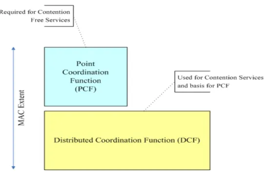
(15) (3) Transmission time of the polled stations is unknown (4) Option mode, PCF has not been widely implemented. 2.1.3 Coexistence of DCF and PCF The DCF and the PCF may in somehow coexist in a manner that allows both to operate concurrently within the same BSS (Figure 2.1). When a PC is operating in a BSS, the two access methods alternate, with a contention-free period followed by a contention period.. Figure 2.1 MAC architecture. Nevertheless, problems associated with the coexistence of DCF and PCF are addressed in the recent research [7] [8] [9], and especially PCF performs poorly in the existence of DCF. Furthermore, because DCF and PCF do not differentiate between traffic types and sources, the IEEE is proposing enhancements in 802.11e to both coordination modes to support QoS.. 2.1.4 IEEE 802.11e Wireless LAN for Quality of Service To support QoS, IEEE 802.11 Task Group E currently defines enhancements to 5.
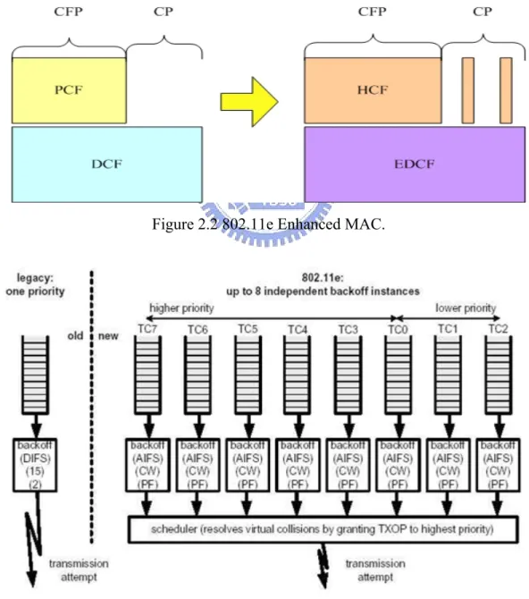
(16) the above-described 802.11 MAC, called 802.11e [10], which introduced Enhanced Distributed Coordination Function (EDCF) and Hybrid Coordination Function (HCF).. 2.1.4.1 Enhanced Distributed Coordination Function (EDCF) The EDCF in 802.11e is the basis for the HCF, like the DCF in 802.11 provides services for PCF (Figure 2.2). EDCF defines the idea of traffic categories (TCs) for supporting traffic differentiation, and each station has eight TCs, or priority levels (Figure 2.3).. Figure 2.2 802.11e Enhanced MAC.. Figure 2.3 8 Traffic Categories (TCs). 6.
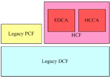
(17) With EDCF enabled, stations try to send data after detecting channel being idle for an Arbitration Interframe Space (AIFS) defined by the corresponding traffic category. A higher-priority traffic category will have a shorter AIFS than a lower-priority traffic category. Therefore stations with low-priority traffic will have to wait longer than those with high-priority traffic before accessing the medium. If the backoff counters of two or more parallel TCs within a station reach zero (collision) at the same time, a scheduler inside the station will treat this event as a virtual collision without recording a retransmission. Then the TC with higher-priority will be provided with Transmit Opportunity (TXOP), and the other TC with lower-priority will have to wait for another period of time. The EDCF provides differentiated services based on traffic categories, but the relative performance is not easy to control since the performance is not proportionally to the backoff factor ratios and depends on the number of contending stations.. 2.1.4.2 Hybrid Coordination Function (HCF) The HCF is proposed by IEEE 802.11e to improve polling mechanism of PCF, and provides policing and deterministic channel access by controlling the channel through the Hybrid Coordinator (HC). Unlike the PCF, which used different frame exchange sequences in the CP and CFP, the HCF defines a uniform set of frame exchange sequences that are usable at any time. The HCF can operate in CFP and CP, and supports both InterServ and DiffServ. Within the HCF, there are two access mechanisms called the Enhanced Distributed Channel Access (EDCA) and HCF Controlled Channel Access (HCCA) (Figure 2.4).. 7.
(18) Figure 2.4 Draft of 802.11e architecture.. The EDCA is an extension for 802.11 DCF, and supports 8 priorities (traffic classes). With the admission control in EDCA, the contention window and backoff times are adjusted to change the probability of gaining medium access to favor higher priority classes. Figure 2.5 shows the priority values (0 to 7) which is identical to the IEEE 802.1D priorities.. Priority. User priority. 802.1D. Access Category (AC). Designation. Lowest. 1. BK. AC_BK. Background. 2. -. AC_BK. Background. 0. BE. AC_BE. Best Effort. 3. EE. AC_BE. Best Effort. 4. CL. AC_VI. Video. 5. VI. AC_VI. Video. 6. VO. AC_VO. Voice. 7. NC. AC_VO. Voice. Highest. Figure 2.5 EDCA supports 8 priority values (traffic classes). 8.
(19) The HCCA uses a HC to centrally manage medium access. Under control of the HC, a nearly continuous sequence of frame exchanges can be maintained, with short, fixed delays between frames. Moreover, HCCA guarantees strict QoS for specific flows from applications with individual QoS parameter.. 2.1.5 Other Enhanced MAC Layer Mechanisms In addition to the mechanisms proposed by IEEE 802.11 Working Group E discussed above, there have been a number of proposals which modify or enhance the MAC protocol in WLANs to support differentiated services [11][12][13][14][15]. However, all of these methods focus on scheduling and fairness on individual wireless MAC without considering the dynamic nature of the whole wireless networks.. 2.2 Network-layer QoS Support Past research in routing for wireless network, such as ad hoc networking, focus on providing QoS routes and efficient routing. In [16], the authors present a cluster-based approach which can inform the source regarding the bandwidth and QoS available to any destination in the wireless network. This enables the establishment of QoS connections within the wireless network and the efficient support of real time, multimedia traffic. In [17], author proposed a distributed QoS routing scheme which selects a route with sufficient resources to satisfy certain delay (or bandwidth) requirement in a dynamic multi-hop mobile environment. Their proposed algorithms also work with imprecise state information (delay, bandwidth, and cost) to select the best qualified one among multiple paths. In mobile ad hoc network, the locations and resources of mobile nodes may vary dynamically. The state information used in the traditional ad hoc routing protocol. 9.
(20) (DSDV, DSR, and AODV) can become obsolete very quickly due to node mobility. Thus a predictive location-based QoS routing scheme [18] is proposed, which is based on a low-cost location-resource update protocol to assist predicting future routes before existing routes break and avoiding route re-computation delay. In addition to the research on QoS routing, there have been some work done on load-balancing routing for wireless access networks. A new distributed routing algorithm [19] performs the dynamic load-balancing for wireless access networks. The algorithm introduced the idea of load-balanced backbone tree, which simplifies routing and avoids per-destination state for routing and per-flow state for QoS reservations. From the discussion above, we found that their research mainly focus on multi-hop wireless networks thus each node has to find a QoS route to egress node via connecting to multiple nodes within the network. However, our proposed method will focus on infrastructure wireless network, which means each node in the wireless network will directly connect to the nodes through an access point (one hop).. 2.3 Hardware-based QoS Support Recently, wireless vendors like Cisco [20] and OriNOCO [21][22] have their wireless client adapters equipped with site-survey tools to detect the signals from the neighbor access points. With the tool users can learn statistical information regarding the access points, including nearby access points, signal strength and quality, receive and transmit statistics, and link status. As to the data gathered by this tool, users can decide which access point to associate with for the future communication. For example, Figure 2.6 illustrates the available sites detected by OriNOCO wireless PC card. From the figure listed below, we learn that there are three available access points. 10.
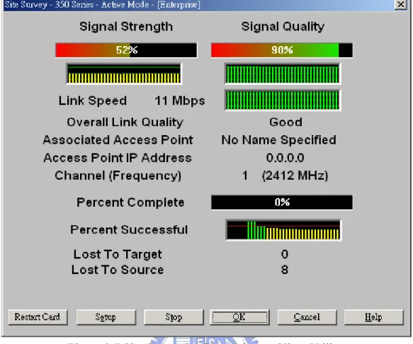
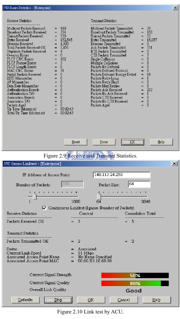
(21) surrounding us: CC201, default, and NCTU. Each of them have the equal signal strength, but we choose to associate with AP CC201 as suggested by Boingo software.. Figure 2.6 Available signals by Boingo.. In Figure 2.7 and 2.8, Cisco’s Aironet Client Utility (ACU) provides more information on signal strength and link quality. From the figures below we have been informed of the channel, network type, power save mode, AP MAC address, and etc. Moreover, we present the delivery and transmission statistics in Figure 2.9, and the result of link test in Figure 2.10.. 11.
(22) Figure 2.7 Site Survey by Cisco Aironet Client Utility.. Figure 2.8 Aironet client adapter status. 12.
(23) Figure 2.9 Receive and Transmit Statistics.. Figure 2.10 Link test by ACU. 13.
(24) To some extent these information may be helpful for users while selecting access points, in most cases, mobile users will eventually choose the AP with stronger signal strength and better link quality. However, this does not guarantee that you will have better quality of service as there might be many users share the same AP with you at the same time. Moreover, it is burdensome work for wireless users to keep tracking the status of each AP available to them during the connection. Also, these utilities only inform the users of surrounding APs rather than distant and least-loaded APs. For instance, a traveler in the airport is waiting for his flight to LA and is situated at gate A1. Since LA is a popular scenic spots, you can imagine that there will be much more people located in A1 gate rather than other gates. B1, another airport gate, is about two or three corners next to A1 and with fewer passengers than A1. However, the site-survey tool only notifies the traveler about the APs installed in the ceiling of A1, A2, or nearby gates but cannot detect the APs of B1 due to the longer distance and physical obstructions (people, stores, and walls). In our proposed system we are trying to solve this problem.. 2.4 System-based QoS Support Microsoft Corp. has incorporated a new feature called Microsoft Wireless Configuration Manager (MWCM) in its released operating systems (Windows 2000/XP). While the broadcast beacons from APs are detected by wireless PC card, the configuration manager will pop up a message to notify the users of the available wireless networks. From Figure 2.11, the manager presents three usable networks to associate with. In Figure 2.12, MWCM helps users configure the settings of wireless network such as the switching between infrastructure and ad hoc modes, security option (Wired Equivalent Privacy, WEP), and 802.1x authentication support. 14.
(25) (Extensible Authentication Protocol, EAP; Remote Authentication Dial In User Service, RADIUS).. Figure 2.11 Wireless Network Connection.. Figure 2.12 Wireless Configuration Manager. 15.
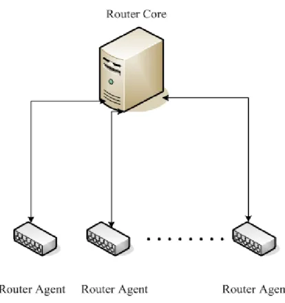
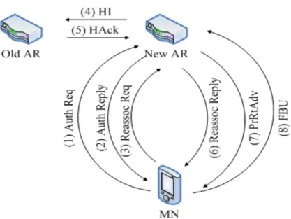
(26) In [23], the authors introduce DIRAC, a software-based router system that is designed for wireless networks to support three wireless network services: link-layer assisted fast handoff, channel-adaptive scheduling, and link-layer enforced policing. DIRAC is a distributed router architecture that consists of a Router Core (RC), and several Router Agents (RAs) at each access point/base station (Figure 2.13).. Figure 2.13 Distributed Wireless Router Architecture. The RAs send wireless link-layer information to the RC and the RC dictates the corresponding control actions to the RA. This interaction allows the router to make adaptive decisions based on link-layer information feedback. For example, when a mobile user roams from an old access router to a new one, link-layer handoff will happen first. With the DIRAC system framework support, they use the ReAssociation message of link-layer handoff process that precedes the network layer, and use it as the event that triggers the network-layer handoff service. Figure 2.14 shows the message flow of the protocol.. 16.
(27) Figure 2.14 Link-layer informed fast handoff.. Although DIRAC enables wireless protocol and provides router services for wireless networks, it is not able to inform the mobile users ahead of moving to the access point/base station with more available resources. Hence, we will take this feature into account in our system design, and here we define the action of informing the mobile uses beforehand as anticipative assistance.. 17.
(28) Chapter 3 Proposed Approaches Following the background and related work in Chapter 2, this chapter introduces the motivation behind our proposed approach and the design details as well. Further, we also describe the desired goals to be achieved in the last section.. 3.1 Motivation In recent years, the demand for wireless services, such as security protection, high-rate data delivery, easy configuration, and QoS support for real-time applications, has greatly increased. In order to fulfill the requirements of wireless QoS, various mechanisms have been proposed to deal with different level such as MAC-layer enhancement, network-layer assistance, system framework support, and hardware solutions. Through the relevant discussion in Chapter 2, we have learned that wireless devices and utilities will sense the stronger signal and are going to associate with the access point near to the users by default. Besides, we usually consider that the best link quality guarantees the best quality of service for the entire data communication. However, you may find a contrary situation because the data rate seems to be extremely low even though you choose the ‘qualified’ AP. Is the AP really a qualified one for you? You may take the following scenarios into consideration:. [Scenario 1] There are four access points located on the ceiling of hotels or conference rooms (Figure 3.1). We in here assume that there might have physical obstructions such as walls, furniture, or pillars between the wireless coverage of each access point. While you walk into the lobby, the wireless utilities will soon notified you of the AP-1 as 18.
(29) your best choice since AP-1 is closer to you and features stronger signal than the other access points. Nevertheless, it is obviously that AP-1 can not perform better than AP-4 because it is shared by more mobile users so that has less available bandwidth for you. Since you are not aware of the overall user distribution in the network, you probably get into a hot spot (population centre) without any notice.. Figure 3.1 Wireless scenario. [Scenario 2] In Figure 3.2, you are located at G4 in CKS international airport to wait for your flight to San Francisco (SF). The departure time of the flight is 11:30am, and you will be on board about half an hour later. Since SF is a famous tourist spot, G4 is much more crowded than the other gates and travelers around the G4 access the wireless Internet to kill time. At this moment, your boss phones you and asks you to send some documents urgently via email right away. You promptly attempt to send the email, but 19.
(30) you may find the transmitting speed is very slow and can not make it through prior to the taking off. The time is approaching and you have nothing to do with this dilemma. Meanwhile, G7, another gate whose flight is destined for Cairo, is three corners away from G4 and with much fewer people. Unfortunately, you were not aware of the information, hence, the key missing piece is a system framework that is able to inform you the overall status of the network environment, and provides assistance beforehand.. Figure 3.2 Airport gates. Based on the above ideas, we propose a novel approach called anticipative agent assistance, AAA. AAA is a centralized framework which provides various forms of interaction between users and agents in order to improve the quality of service over wireless networks. In the following sections, we present the system design and implementation details. 20.
(31) 3.2 Anticipative Agent Assistance (AAA) 3.2.1 Design Rationale of AAA Anticipative Agent Assistance, AAA, is designed for supporting users to acquire better quality of service through interaction with agents. Basically, AAA is a centralized architecture which is composed of a sever agent (SA) and numerous client agents (CAs) installed at each access point/base station. Figure 3.3 illustrates the architecture of AAA.. Figure 3.3 AAA architecture.. The connection between SA and CAs is wired, and CAs at access points/base stations provide wireless coverage for the mobile users. Each CA is independent and can arbitrarily join or leave the AAA group. For example, when a mobile user enters the wireless domain under CA-1 and requests AAA support, CA-1 will generate an assistance request message and forward it to SA. SA refers to its database and control algorithm to calculate the qualified CA list and sends this information to the user 21.
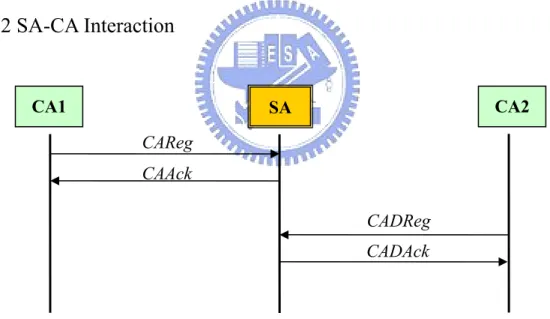
(32) through CA-1. With AAA enabled, each mobile user will soon be advised whether he or she needs to move or not before starting any application or service. The number of CAs can be supported as many as possible, and CAs can also be applied in different subnets to provide extensive services. Moreover, AAA adopts the centralized design instead of decentralized approach due to the following concerns: (1) Make it easy to control and monitor the entire network status, (2) Lighten the load of access points (CAs), and (3) Reduce the overhead caused by intercommunication among CAs. In the following sections, we are going to describe three forms of interaction in AAA system, including SA-CA interaction, CA-MN interaction, and SA-CA-MN interaction. We also use Figure 3.3 as reference topology in the following discussions.. 3.2.2 SA-CA Interaction. CA1. CA2. SA CAReg CAAck CADReg CADAck. Figure 3.4 SA-CA interaction.. There are two procedures defined in the SA-CA interaction (Figure 3.4), including the registration procedure and deregistration procedure. First, the registration process is initialized by a new CA. When a CA wants to join an AAA group, it needs to start the registration process by sending a CAReg message to SA. The CAReg message contains the essential information such as CA’s ID (MAC 22.
(33) address of CA), CA’s IP address, X-coordinate, Y-coordinates, Z-coordinate, number of mobile users, and available bandwidth. Once the registration requested by a CA is approved, a CAAck message initialized by SA will be sent back to the CA to finish the registration procedure. Otherwise, a CAFail message with failure code will be sent to CA. Second, if a CA would like to quit the AAA group, it must send a CADReg message to SA for reminding SA to remove its record from CA-record (Table 3.1).. ID. IP. Loc_X. Loc_Y. Loc_Z. MN. Bw. CA1. 1.0.0.0. 50.0. 50.0. 0.0. 5. 11Mb. CA2. 2.0.0.0. 550.0. 50.0. 0.0. 3. 54Mb. CA3. 3.0.0.0. 550.0. 550.0. 0.0. 8. 11Mb. CA4. 4.0.0.0. 50.0. 550.0. 0.0. 1. 54Mb. Table 3.1 CA-record maintained in SA.. SA maintains a CA-record in its database as reference and input for future assistance queries from all CAs. All necessary information is stored in SA rather than CAs, and SA also takes charge of the mutual communication among CAs. Thus, CA is exempted from maintaining an individual database and frequently communicating with other CAs. A lightweight CA has been fulfilled via the design of centralized architecture.. 3.2.3 CA-MN Interaction In the interaction between CA and MN (mobile node or user), there are three kinds of procedures (Figure 3.5). The first one is advertisement procedure. Each CA at an access point/base station periodically broadcasts advertisement messages to its 23.
(34) wireless coverage area. Considering the overall network performance the frequency of advertisement broadcasting will be set as once per minute. The CAAdv message is composed of CA’s ID, CA’s IP address, elapsed time, and AAA enforcement option. Elapsed time field in CAAdv message defines the valid lifetime of an advertisement, and AAA enforcement option (ON/OFF) is to determine whether to ask all mobile users to enable AAA support in their settings for the purpose of load-balance. The default value of AAA enforcement option is OFF, that means we allow mobile users to decide whether to accept or decline AAA support in most cases.. MN1. MN2. CA CAAdv. CAAdv. ProbeReq MNReg MNAck MNDReg MNDAck Figure 3.5 CA-MN interaction.. Upon receiving the advertisements from CA, MN will soon check its AAA setting. If the AAA is configured as ON, MN will send a ProbeReq message to CA for requesting AAA services (detailed discussion in next section); if the value of AAA is OFF, MN acts as a normal node in the wireless network. After that, MN may move to another wireless domain of a new CA or stay with the original CA. Then MN has to initiate a registration process which sends a MNReg message to the corresponding CA, and the content of message includes MN’s ID, MN’s IP address, AAA support, QoS 24.
(35) option. The value of AAA support is based on users’ AAA setting, and QoS option will be introduced in the SA-CA-MN interaction. While CA accepts registration request from MNs, it will update its information in SA’s CA-record and a registration acknowledgement will be sent back to MNs. The last procedure in CA-MN interaction is deregistration. If a MN intends to leave for other locations, it starts a deregistration process which sends a MNDReg message to the attached CA and waits for the reply to terminate the procedure. In the meantime, when CA receives the MNDReg request from MNs, it then updates its data in SA’s CA-record.. 3.2.4 SA-CA-MN Interaction Since MN has two settings, AAA support and QoS option, hence the combination of these two values will result in three different types of interaction (QoS can be ON only when AAA is ON). We describe these interactions in three cases, including [AAA/QoS – OFF/OFF], [AAA/QoS – ON/OFF], and [AAA/QoS – ON/ON].. Case 1: [AAA/QoS – OFF/OFF]. MN. CA-1. CA-2. SA. CA-3. MNReg CF+MNReg CF+MNAck MNAck Figure 3.6 Message flow in Case 1.. 25. CA-4.
(36) If both AAA and QoS are disabled in MN’s configuration, MN will behave as an ordinary mobile node in the wireless network. It seems that the AAA system never exists. However, there is still one action needed to be done by MN, the registration process. When MN enters the scope of CA-1, it soon hears the advertisement and then sends a MNReg message to CA-1. After checking the value of AAA field, CA-1 generates a CF+MNReg message to SA for updating the field, number of mobile users, in CA-record. When the CF+MNReg message arrives at SA, SA processes the request and modifies the corresponding records. Once the alteration has been complete, a CF+MNAck message is created by SA to inform CA-1 of successful modification. Finally, CA-1 sends a MNAck message to terminate the registration procedure. The detailed message flow is elaborated in Figure 3.6.. Case 2: [AAA/QoS – ON/OFF]. MN. CA-1. CA-2. SA. CA-3. CA-4. ProbeReq CF+PbReq CF+BstAck BstAck MNReg CF+MNReg CF+MNAck MNAck. Figure 3.7 Message flow in Case 2. In case 2, the AAA support is turned on and QoS option is turned off. While a 26.
(37) MN gets into the wireless coverage of CA-1, it soon senses the advertisement and checks its AAA setting. Since the AAA is set as ON, then MN produces a ProbeReq message to CA-1 right away. The ProbeReq message contains MN’s ID, MN’s IP address, X-coordinate, Y-coordinate, Z-coordinates, and distance-sensitive option. The distance-sensitive option is used in the CalBest algorithm described below and is configured by MNs. CA-1 checks the type of arrival message and attaches its IP address to the end of message so as to generate a new message, CF+PbReq. The CF+PbReq message is forwarded to SA. SA recognizes the CF+PbReq message as an AAA query then makes use of the CalBest algorithm to output the recommended movement in the CF+BstAck message. The CalBest algorithm takes four parameters as its input, including X-coordinate, Y-coordinate, Z-coordinate, and distance-sensitive option in the ProbeReq message. If the distance-sensitive option is OFF, which means to select a least-load AP without considering the distance between the mobile user and the new AP, CalBest sorts the CA-record based on the number of mobile users and available bandwidth. In table 3.1, CA-4 will be recommended to the MN in the end. On the other hand, if the distance-sensitive option is set as ON, CalBest algorithm first repeats the sort procedure described above. After that, the qualified finalists (with slighter load than current AP) are sorted again on the basis of the distance to the mobile user. In table 3.1, CA-2 replaces CA-4 to be the best choice. Following the output of CalBest, SA generates a CF+BstAck message to CA-1. CA-1 informs MN of recommended movement by sending a BstAck message. MN moves to the location as the message suggests and initiates the regular registration procedure present in Section 3.2.3. Figure 3.7 illustrates the message flow among SA, CA, and MN.. 27.
(38) Case 3: [AAA/QoS – ON/ON] With the AAA enabled (AAA support is ON), this guarantees mobile users the quality of service in the beginning. In order to keep monitoring and maintaining the quality of the ongoing connection, we introduce the QoS option to the MNs. The purpose of QoS option is to periodically check the throughput (delay or jitter) of a connection. Once the value of throughput (delay or jitter) is decreased below a specified threshold for accumulative sixty seconds, a ProbeReq messages will be automatically generated and sent to the corresponding CA on behalf of the MN. For instance, a MN in case 2 accepts the suggestion thus moves from a dense area (CA-1) to a sparse area (CA-4). After arriving CA-4 area, MN starts the applications and the quality of service is definitely guaranteed in the beginning. As time passed by, there are some users who disable the AAA support and enter into the wireless coverage of CA-4. Nevertheless, MN was not aware of other users’ coming, and the throughput of the connection drop drastically. With the feature of QoS option, a monitor mechanism in MN will spontaneously be enabled and keep tracking the throughput of the connection. If the throughput is under the threshold for accumulative sixty seconds (can be changed by users), then the monitor mechanism will send a ProbeReq message to CA-4 for another AAA query (same procedure in case 2). Consequently, MN will soon be advised to move to another area to gain better services. Therefore, the joint use of AAA support and QoS option will ensure the quality of service for the entire connection. The threshold setting is based on the class of service, and different services have different requirements for throughput, delay, and jitter. Table 3.2 shows the threshold for service class. Moreover, Figure 3.8 demonstrates the message flow in case 3.. 28.
(39) Code. Class of Service. Throughput. Delay. Jitter. 0. Default. T_D. D_D. J_D. 1. Best effort. T_BE. D_BE. J_BE. 2. Voice. T_VO. D_VO. J_VO. 3. Video. T_VI. D_VI. J_VI. 4. Reserved. -. -. -. Table 3.2 Threshold for service class.. MN. CA-1. CA-2. SA. CA-3. CA-4. ProbeReq CF+PbReq CF+BstAck BstAck MNDReg CF+MNDReg CF+MNDAck MNDAck MNReg CF+MNReg CF+MNAck MNAck Figure 3.8 Message flow in Case 3. In Figure 3.8, a ProbeReq message has been automatically created and sent to the CA-4. Meanwhile, MN waits for the BstAck message from SA. Once the BstAck 29.
(40) message is received by a MN, MN deregisters with CA-4 before moving to the recommended area, CA-2. While the deregistration procedure is complete (MN receives the MNDAck message), MN immigrates to CA-2 and then initiates the regular registration process at the same time.. 3.2.5 Solicitation In order to make AAA system more flexible, we introduce another feature to the MNs, solicitation function. In the original design of AAA system, AAA service is requested through sending out a ProbeReq message by MNs. However, a ProbeReq message only can be generated when the value of AAA support or QoS option is turned on (See Section 2.2.3, Section 2.2.4). Namely, this prevents mobile users from asking service whenever needed. With the support of solicitation function, MN is allowed to manually send a Solicitation message to request AAA service anytime. Figure 3.9 shows the message flow in detail.. MN. CA-1. CA-2. CA-3. SA. Solicitation CF+PbReq CF+BstAck BstAck MNReg CF+MNReg CF+MNAck MNAck. Figure 3.9 Solicitation.. 30. CA-4.
(41) When a MN does not accept the transmission quality, it could quickly send a Solicitation message to request AAA service rather than waits for later reaction initiated by QoS option. In Figure 3.9, a MN sends a Solicitation message to the currently attached CA, CA-1, and waits for the advices from SA. Meanwhile, MN deregisters with CA-1 so as to migrate to other location. Afterward MN moves to CA-3 and begins the regular registration procedure. Thus, the solicitation function gives MNs the great flexibility supported by our AAA system, no matter automatically or manually.. 3.3 Design Goals The AAA system is mainly responsible for managing the control information of the entire wireless access points, outputting the potential AP list with our CalBest algorithm, and then ahead informing the users of AP with better service. Through the interactions with agents, MNs are expected to acquire anticipative assistance by our AAA system. Our design goals are: (1) to reduce the transmission delay, (2) to increase the throughput, (3) to improve the overall network utilization, (4) to accommodate more users to access the network, and (5) to provide load-balancing mechanism. Goal (1) and (2) can be easily achieved by the joint use of AAA support and QoS option. With these two features, MNs should be advised to migrate to the wireless area with slight load and have the better quality of service. Furthermore, we fulfill Goal (3), (4), and (5) via the AAA enforcement option in the CAAdv advertisement message broadcasted by CAs. Once the AAA enforcement option is turned on, AAA system will require all mobile users to be evenly distributed to different areas for the load-balancing consideration. Plus, the AAA enforcement option is superior to the. 31.
(42) other options. By way of enabling the AAA enforcement option, it will prevent users from aggregating in specific area so as to improve the overall network utilization. In next chapter, we are going to present the performance evaluation of our proposed approach.. 32.
(43) Chapter 4 Performance Evaluation In this chapter, we investigate the performance of the proposed method presented in Chapter 3. We use the most popular network simulator, ns-2 version 2.27 [24] (latest released Jan 18, 2004), with various scenarios and configurations to measure the AAA system. The performance evaluation comprises three sets of test, including (1) individual user AAA-support enabled, (2) individual user AAA-support and QoS-option enabled, (3) AAA-enforcement-option enabled (all users are advised by the AAA system). The main goal of the test is to demonstrate the benefit to individual user behavior and overall network utilization.. 4.1 Individual User AAA-support Enabled 4.1.1 Simulation Scenario I. Figure 4.1 Simulation scenario I. 33.
(44) Figure 4.1 illustrates the network topology in our first test set. There are four CAs (attached at access points/base stations) separately connecting to the SA with a 100 Mbps/1 ms wired link (the link delay is composed of layer 2 process time and propagation time), and so is the connection between a CN and a SA. 802.11b is used to enable the wireless communication for mobile users and CAs. The mobile users start the FTP application destined to the CN with TCP Reno traffic, and here we simulate that a new user (MN) is going to enter CA-1 area (near the entrance). The simulation time is 300 seconds. Besides, we have CA-1 with different initial user distributions (from 0 to 5) to see what the new user (MN) will benefit from our AAA support. The user distributions for CA-2, CA-3, and CA-4 are 3, 2, and 0 respectively.. 4.1.2 Result and Analysis I. Throughput (Kbits/sec). 2500 2000 1500 no_AAA AAA. 1000 500 0 1. 2. 3. 4. 5. 6. Number of users at CA Figure 4.2 MN’s throughput. Figure 4.2 shows the MN’s throughput under various user distributions at CA-1. When MN enters the wireless coverage of CA-1 where one user was there prior to the 34.
(45) MN’s arrival (two in total if including MN), MN’s throughput is about 1079 Kbps. However, the throughput is decreased to 458 Kbps while the number of users reaches 6. We can be sure that the throughput is definitely going down if more users join to CA-1 group and the MN is not aware of the situation. Namely, the more users aggregate at CA-1, the lower throughput MN1 will get. On the other hand, with the AAA support, the throughput of MN has been improved a lot. MN maintains the throughput at 2158 Kbps no matter what the number of users at CA-1 is. This is because MN enables the AAA-support so as to be ahead directed by AAA system to move from CA-1 to CA-4 before starting the FTP application. Thus, no one will compete for the resource with MN at CA-4 and MN will surely be better served than at CA-1. Moreover, the sending rate and RTT are illustrated in Figure 4.3 and 4.4. With the AAA-support enabled, MN’s average RTT is 7.36 ms. One thing to be noted here is that both the sending rate and RTT are somewhat unstable when the number of users increases. From Figures 4.3, we can easily recognize that the sending rate with six users is not as smooth as that with AAA support. The same situation is happened to RTT as well. The RTT with six users can range between 25 ms and 80 ms, but between 5 ms and 9 ms with AAA support. In addition, we also attempt to add more users to CA-1 (more than 7 users in total). However, the RTT dramatically increases to hundred ms and the sending rate becomes very unstable at the same time. The reason is that the queue size of AP overflows thus seriously deteriorates the quality of service for mobile users. Hence, the probability of aggravating QoS will be substantially decreased with the help of AAA system. Figure 4.5 summarizes the user distribution at each CA. Due to the suggestion given by AAA-support, the number of users at CA-1 decreases from 6 to 5, and that at CA-4 increases from 0 to 1.. 35.
(46) 2500. Sending Rate (Kbps). 2000 1 2 3 4 5 6 AAA. 1500. 1000. 500. 0 0. 60. 120. 180. 240. 300. Time (s) Figure 4.3 MN’s sending rate.. 90. RTT (ms). 80. 1. 70. 2. 60. 3. 50. 4. 40. 5. 30. 6 AAA. 20 10 0 0. 60. 120. 180. 240. 300. Time (s). Figure 4.4 Round trip time for MN’s FTP application. 36.
(47) User distribution 7 Number of mobile users. 6 5 4. no_AAA. 3. AAA. 2 1 0 CA-1. CA-2. CA-3. CA-4. Figure 4.5 User distribution at each CA.. 4.1.3 Simulation Scenario II. Figure 4.6 Simulation scenario II. 37.
(48) Figure 4.6 shows the simulation scenario II. It differs from scenario I in the direction of data transfer, link capacity, and application. In scenario II, CN will be the sender and initiate the audio flows destined to the mobile users. The audio flow is the CBR traffic with 64 Kbps sending rate and 210 Byte UDP packets. While the MNs are located within the transmission range of AP, then CN sends the audio flow to MNs. The link capacities for CN-SA and SA-CA have been changed to 10 Mbps/1 ms, 1Mbps/10 ms, respectively. The simulation time is same as scenario I, 300 seconds.. 4.1.4 Result and Analysis II Figure 4.7 shows the delay for audio flow received at a MN. From the figure we learn that the delay is proportional to the number of mobile users. The delay is from 0.014 second to 0.023 second. If the AAA-support is enabled, the delay can be reduced to as low as 0.014 second.. MN, audio flow, 64Kbps, 210Byte. 0.025. 1. 0.023 Delay (s). 2 0.021. 3. 4. 0.019. 5 0.017. 6. AAA. 0.015 0.013 0. 60. 120. 180. 240. Time (s). Figure 4.7 End-to-end delay for audio traffic. 38. 300.
(49) Furthermore, we also attempt to add more users as discussed in Section 4.1.2. Not surprisingly, the end-to-end delay greatly increases to hundreds of milliseconds (647 ms or above) and the sending rate becomes very unsteady. The reason is that the queue size of AP overflows thus seriously deteriorates the quality of service.. 4.2 Individual User AAA-support and QoS-option Enabled 4.2.1 Simulation Scenario III We use the same network topology (Figure 4.1) in scenario III. The initial user distribution will be 0, 3, 2, and 0 for CA-1 to CA-4. Since the MN enables both AAA-support and QoS-option, MN is directed to CA-1 as recommended by AAA system (with lease load and shortest distance) in the beginning. In order to verify the benefit introduced by QoS-option, we add one mobile user every 30 seconds at CA-1 until the total number of users raises to 6. The QoS threshold is set as 1000 Kbps. The other settings such as link capacity, application, and transfer direction, are identical to those of scenario I. Furthermore, for service continuity, every mobile user has Mobile IP [25] enabled while migrating to other CAs.. 4.2.2 Result and Analysis III Figure 4.8 and Figure 4.9 illustrate the sending rate and RTT for MN’s FTP application with or without the support of QoS-option. In Figure 4.8, the MN’s throughput decreases from 2064 Kbps to 1008 Kbps when adding a user to CA-1 at 30th second. At 60th second, another user gets into the CA-1 area (3 mobile users in total), the throughput quickly drops to 712 Kbps. At the same time, the monitor mechanism launched by QoS-option keeps tracing the throughput based on the specified threshold for the following 60 seconds.. 39.
(50) 2500. Throughput (Kbps). 2000 1500 no_QoS QoS. 1000 500 0 0. 60. 120. 180. 240. 300. Time (s) Figure 4.8 MN’s sending rate.. 60 50. RTT (ms). 40 no_QoS QoS. 30 20 10 0 0. 60. 120. 180. 240. 300. Time (s) Figure 4.9 Round trip time for MN’s FTP application. 40.
(51) At 120th second, however, the total number of mobile users has reached 5 and MN’s throughput keeps decreasing. Thus, the monitor mechanism automatically generates a ProbeReq message on behalf of MN to request AAA’s support. After that, MN takes the suggestion so as to move from CA-1 to CA-4 at 122nd second. During the handoff (122nd sec – 131st sec), MN also starts the Mobile IP to ensure the service continuity. At 131st second, MN arrives at CA-4 and the throughput goes up to 2168 Kbps again. Meanwhile, RTT rapidly decreases from 32 ms to 6 ms. On the contrary, without the QoS-option, MN’s throughput can drop drastically to as low as 336 Kbps and RTT can be raised as high as 54 ms.. 7. Number of mobile users. 6 5 4. no_QoS. 3. QoS. 2 1 0 0. 30. 60. 90 120 150 180 210 240 270 300 Time (s). Figure 4.10 User distribution at CA-1. Figure 4.10 summarizes the user distribution at CA-1 for the entire trace. As a result of the MN’s migration (at 122nd second) and new user’s participation (at 150th second), the number of users keeps the same at 150th second. In addition, the overall user distribution is elaborated in Figure 4.11. 41.
(52) User distribution. Number of mobile users. 7 6 5 4. no_QoS. 3. QoS. 2 1 0 AP1. AP2. AP3. AP4. Figure 4.11 Overall user distribution.. 4.3 AAA-enforcement-option Enabled 4.3.1 Simulation Scenario IV In. this. section, we. present. the. load-balancing. mechanism. enabling. AAA-enforcement option in the advertisement messages. The scenario is shown in Figure 4.12. CN connects to SA through a 10 Mbps/1 ms link, and the connection between SA and each CA is a 2 Mbps/2 ms link. MNs are the senders which begin the FTP application with TCP Reno traffic, and the traffic is received at CN. In general, users tend to be located in particular area for several reasons, such as the network accessibility, the location of power outlets, and personal fondness. Namely, the mobile users are unevenly distributed at each CA. Therefore, we assume that the user distribution will be 5, 3, 0, and 0 for CA-1 to CA-4 without AAA enforcement. In the following section, we will examine the queue-size and queue-drop of the links between SA and CAs to see what we benefit from this feature. The default queue size is 50, and the simulation time is 300 seconds.. 42.
(53) Figure 4.12 Simulation scenario IV.. 4.3.2 Result and Analysis IV User distribution. Number of mobile users. 6 5 4 no_AAA. 3. AAA. 2 1 0 CA-1. CA-2. CA-3. CA-4. Figure 4.13 User distribution at each CA. Since the AAA enforcement is enabled in the advertisement messages, every mobile user will be asked to move to the assigned CA while entering the wireless area. 43.
(54) In Figure 4.13 we can see that all the users are equally dispatched to four CAs. From the network administrator’s perspective, this function indeed achieves the load-balancing and reduces the probability of having mobile users congested in certain areas. Furthermore, we in here define the link between SA and each CA (CA-1 ~ CA-4) as Link1 to Link4. Figure 4.14 ~ Figure 4.17 show the queue size of each link. The default queue size of each link is 50 packets. Without the AAA enforcement enabled, the queue size of Link1 can be very fluctuant and ranges between 0 and 49 (Figure 4.14). Once the queue space runs out, it results in the packet drop. From Figure 4.18 we learn that the packet drop for Link1 can be as high as 960 packets. Link2 experiences the same problem at the same time. The range for queue size of Link2 is between 13 and 49, and also leads to 261 packet drops. Since all users congregate in CA-1 and CA-2, the queue sizes for Link3 and Link4 are always zero and without any packet drop. On the other hand, if the AAA enforcement is enabled in the beginning, the packet drop for each link eventually reduces to zero and the queue size of each link keeps steady without overflowing during the entire trace. Figure 4.14 ~ Figure 4.17 illustrates that the queue size for each link ranges between 35 and 37. Thus, this feature not only increases the probability of providing users guaranteed quality of service, but also improves the overall network utilization by load-balancing mechanism. In addition to the advantages presented above, this feature may also accommodate more users to access the wireless network. Generally speaking, a link without large numbers of packet drop shall be very critical to the end users with real-time services. Time-sensitive services, such as VoIP, video, streaming media, and interactive gaming, demand network performance with low latency and high network availability. Users may quit the network due to the quantities of packet drop, high latency, and poor network performance. With the help of AAA enforcement, it raises 44.
(55) the chances to keep the users staying within the network and to allow more users joining to the group. Queue Size 60 50. Packets. 40 Link1 AAA. 30 20 10 0 0. 60. 120. 180. 240. 300. Time (s) Figure 4.14 Queue size for SA-CA1 link. Queue Size 60 50. Packets. 40 Link2. 30. AAA. 20 10 0 0. 60. 120. 180. 240. Time (s). Figure 4.15 Queue size for SA-CA2 link. 45. 300.
(56) Queue Size 40 35. Packets. 30 25 Link3 AAA. 20 15 10 5 0 0. 60. 120. 180. 240. 300. Time (s) Figure 4.16 Queue size for SA-CA3 link.. Queue Size 40 35. Packets. 30 25 Link4 AAA. 20 15 10 5 0 0. 60. 120. 180. 240. Time (s) Figure 4.17 Queue size for SA-CA4 link.. 46. 300.
(57) Queue Drop 1200 1000. 960. Packets. 800 no_AAA AAA. 600 400. 261. 200 0. 0. 0 0. 0 0. Link1. Link2. Lin3. Link4. 0. Figure 4.18 Queue drop for each link.. 4.3.3 Simulation Scenario V. Figure 4.19 Simulation scenario V. The scenario V is shown in Figure 4.9. The link between CN and SA remains the 47.
(58) same, but the connection between SA and each CA is changed to 1 Mbps/10 ms. CN is the sender which acts as a streaming media server and transmits video stream to mobile users. The video stream is the VBR traffic with 384 Kbps sending rate and 800 Byte UDP packets. In this scenario, MN will be the first one who enters the CA-1 area. After that, CA-1 takes in one user every 30 seconds until the total number of users increases up to 8. Moreover, following the assumption in scenario IV, we assume that the user distribution will eventually be 8, 0, 0, and 0 for CA-1 to CA-4 without AAA enforcement. In the following section, we are going to see how the delay and loss rate for MN’s application will be affected with the AAA enforcement option.. 4.3.4 Result and Analysis V We first investigate the delay and loss rate of MN without the AAA enforcement enabled. In Figure 4.20, the delay for MN’s video flow is kept as low as 19 ms prior to the 60th second. At 61st second, the delay begins to increase and the total number of users at CA-1 has reached 3. Between 61st second and 160th second, three additional users join to CA-1 (6 users in total), the delay increases steadily but slowly and the loss rate maintains at zero as shown in Figure 4.21. After 160th second, however, both the delay and loss rate suddenly raise and keep going up for the rest of the trace. The 8th user gets into CA-1 area at 210th second, and the delay is as high as 120 ms and loss rate reaches to about 8%. Even though there is no other users joining to CA-1 area after 210th second, the delay and loss rate still keeps aggravating in the later half of the trace (210th – 300th second). In the end of trace, the delay can be raised up to 156 ms and the loss rate climbs up to 22%. On the contrary, if AAA enforcement is enabled, MN and other users will be evenly directed to the four CAs as shown in Figure 4.22. Moreover, the delay for MN maintains the delay at 19 ms for the entire trace, and the loss rate is also reduced to 0% till the end. From aforementioned 48.
(59) discussion, we conclude that with the introduction of AAA enforcement messages, both MN and other mobile users are guaranteed to receive a service at an acceptable level, and the goal of load-balancing can be achieved in the meanwhile. MN, Video flow, 384Kbps, 800byte 0.18 0.16 0.14 Delay (s). 0.12 0.1. no_AAA. 0.08. AAA. 0.06 0.04 0.02 0 0. 60. 120. 180. 240. 300. Time (s). Figure 4.20 Delay for MN’s video flow.. MN, video streaming, 384Kbps, 800byte 25. Loss Rate (%). 20 15. no_AAA AAA. 10 5 0 0. 60. 120. 180. 240. 300. Time (s). Figure 4.21 Loss rate for MN’s video streaming flow. 49.
(60) User distribution 9 Number of mobile users. 8 7 6 5. no_AAA. 4. AAA. 3 2 1 0 CA-1. CA-2. CA-3. CA-4. Figure 4.22 User distribution at each CA.. 50.
(61) Chapter 5 Conclusions In this thesis, we proposed an agent-based system for improving quality of service over wireless networks. The proposed method, AAA system, is mainly responsible for managing the control information of the entire wireless access points, outputting the potential AP list with our CalBest algorithm, and informing the users of AP (or CA) with least load. Through the interaction with agents, mobile users are expected to acquire anticipative assistance by our AAA system. Furthermore, we also introduce the novel idea, QoS option, which allows users to promptly adjust the service quality with AAA system according to specified threshold of throughput, delay or jitter. For the load-balancing purpose, we incorporate the AAA enforcement option in the advertisement messages. With the AAA enforcement enabled, all mobile users will be directed by AAA system based on the load-balancing mechanism. Also, we extend the AAA system with the solicitation function. The solicitation feature allows users to request AAA service whenever needed. We use ns-2 to evaluate the performance of AAA system through simulations with various scenarios and user configurations. By using the proposed method it was shown that AAA system (1) reduces the transmission delay, (2) increases the throughput, (3) improves the overall network utilization, (4) accommodates more users to access the network, and (5) provides load-balancing mechanism. At the end, we conclude this thesis with some possible future work. First, we note that the AAA system is yet to be put into practice. If the system is implemented on the access points/base stations, the network load can be easily controlled and the users will be better served within the wireless network. In addition, AAA system can cooperate with SNMP (Simple Network Management Protocol) to gather more 51.
(62) precise information to be reference when CalBest algorithm makes the decisions for the users. Moreover, users may send a service agreement which indicates the maximum and minimum bandwidth needed for different classes of service to the SA for accurately reserve the resource. Also, SNMP in here can be great help for providing the necessary information to the reservation. Finally, since the AAA system is a design with the server-client architecture, we hope to eliminate the centralized framework by introducing protocol like routing protocols (RIP, OSPF, IGRP or IGRP) to enable the intercommunication between CAs. With the support of this protocol, the system can be simplified in advance.. 52.
(63) References [1] IEEE 802.11b/d3.0 Wireless LAN Medium Access Control (MAC) and Physical Layer (PHY) Specification, August, 1999. [2] D. Tang and M. Baker. Analysis of a Metropolitan-Area Wireless Network. In Proceedings of ACM MobiCom’99, August, 1999. [3] D. Tang and M. Baker. Analysis of a Local-Area Wireless Network. In Proceedings of ACM MobiCom’00, August, 2000. [4] D. Kotz and K.Essien. Analysis of a Campus-wide Wireless Network. In Proceedings of ACM MobiCom’02, September 2002. [5] IEEE 802.11 Wireless LAN Medium Access Control (MAC) and Physical Layer (PHY) Specifications, August, 1999. [6] Anders Lindgren, Andreas Almquist, and Olov Schelén. Quality of service schemes for IEEE 802.11 wireless LANs: an evaluation. Mobile Networks and Applications, Volume 8 Issue 3, June 2003. [7] B. P. Crow, I. Widjaja, J. G. Kim, and P. Sakai. Investigation of the IEEE 802.11 medium access control (mac) sublayer functions. In Proceedings of IEEE Infocom’97, April, 1997. [8] T. M. Veeraraghavan, and N. Cocker. Support of voice services in IEEE 802.11 wireless LANs. In Proceedings of IEEE Infocom’01, Polytechnic University, 2001. [9] M. Visser and M. ElZarki. Voice and Data Transmission over an 802.11 Wireless Network. In Proceedings of IEEE Personal., Indoor and Mobile Radio Conf. (PIMRC’95), September, 1995. [10] S. Mangold, S. Choi, Peter May, Ole Klein, Guido Hiertz, and Lother Stibor. IEEE 802.11e Wireless LAN for Quality of Service. In Proceedings of European. 53.
(64) Wireless’02, Italy, February, 2002. [11] I. Ada and C. Castellucia. Differentiation Mechanisms for IEEE 802.11. In Proceedings of IEEE Infocom’01, March, 2001. [12] G. Bianchi, L. Fratta, and M. Oliveri. Performance Evaluation and Enhancement of the CSMA/CA MAC Protocol for 802.11 Wireless LANs. In Proceedings of the. 7th. International. Symposium. on. Personal,. Indoor,. and. Mobile. Communication (PIMC), 1996. [13] M. Barry, A. T. Campbel, and A. Veres. Distributed Control Algorithms for Service Differentiation in Wireless Packet Networks. In Proceedings of IEEE Infocom’01, April, 2001. [14] H. Kim, and Jennifer C. Hou. Improving Protocol Capacity with Model-based Frame Scheduling in IEEE 802.11-operated WLANs. In Proceedings of ACM MobiCom’03, September, 2003. [15] N. H. Vaidya, P. Bahl, and S. Gupta. Distributed Fair Scheduling in a Wireless LAN. In Proceedings of ACM MobiCom’00, August, 2000. [16] J. Tsai, T. Chen and M. Gerla. QoS Routing Performance in Multihop, Multimedia, Wireless Networks. In Proceedings of IEEE ICUPC, 1997. [17] S. Chen, and K. Nahrstedt. Distributed Quality of Service Rouring in Ad hoc Networks. In Proceedings of IEEE JSAC, Aug 1999. [18] S. H. Shah, and K. Nahrstedt. Predictive Location-based QoS Routing in Mobile Ad hoc Networks. In Proceedings of IEEE ICC’02, 2002. [19] P. Hsiao, A. Hwang, H. T. Kung, and D. Vlah. Load-Balancing Routing for Wireless Access Networks. In Proceedings of IEEE Infocom’01, April, 2001. [20] Cisco Aironet 350 Series (Aironet AIR-PCM 352 Wireless Lan Adapter), March, 2004. [21] Agere Systems Inc. NDIS 5 USB Driver for MS Windows XP, Winter, 2002. 54.
(65) [22] Boingo Software, version 1.1, 2002. [23] P. Zerfos, G. Zhong, J. Cheng, H Luo, S. Lu, and J. Li. DIRAC: A Software-based Wireless Router System. In Proceedings of ACM MobiCom’03, September, 2003. [24] The Network Simulator – ns-2, http://www.isi.edu/nsnam/ns/. [25] C. Perkins. IP Mobility Support. RFC2002, IETF, October, 1996.. 55.
(66)
數據

+7

相關文件
Making use of the Learning Progression Framework (LPF) for Reading in the design of post- reading activities to help students develop reading skills and strategies that support their
Now, nearly all of the current flows through wire S since it has a much lower resistance than the light bulb. The light bulb does not glow because the current flowing through it
During early childhood, developing proficiency in the mother-tongue is of primary importance. Cantonese is most Hong Kong children’s mother-tongue and should also be the medium
Recycling Techniques are Available to Address Specific Pavement Distress and/or Pavement Structural Requirement.. Introduction to Asphalt Introduction
Using this formalism we derive an exact differential equation for the partition function of two-dimensional gravity as a function of the string coupling constant that governs the
This kind of algorithm has also been a powerful tool for solving many other optimization problems, including symmetric cone complementarity problems [15, 16, 20–22], symmetric
An adaptation layer is used to support specific primitives as required by a particular signaling application. The standard SS7 applications (e.g., ISUP) do not realize that
3. Works better for some tasks to use grammatical tree structure Language recursion is still up to debate.. Recursive Neural Network Architecture. A network is to predict the
