Contributed Paper
Manuscript received December 21, 2003 0098 3063/04/$20.00 © 2004 IEEE
Optimal Frame Memory and Data Transfer Scheme for
MPEG-4 Shape Coding
Kun-Bin Lee, Hao-Yun Chin, Nelson Yen-Chung Chang, Hui-Cheng Hsu, and Chein-Wei Jen
Abstract — An optimal frame memory and data transferscheme is proposed for MPEG-4 shape coding in embedded systems. The proposed alpha frame buffer scheme contains two approaches. First, a distributed tile-based memory organization is used to efficiently support the time-varying size of alpha plane. Second, a compression scheme is used to reduce the number of memory access to and the size of the alpha frame memory. Under the criteria of MPEG-4 standard, the size of alpha frame memory can be reduced to 50% by introducing a small index table (2.73%-5.08% of the original frame memory size). A coarse assessment shows that the number of memory reference can be reduced to 56.25%. On the other hand, the proposed data transfer scheme combines the run length coding and addressing mode to reduce average data transfer time to 9.39%. Therefore, the shared system bus can be kept as free as possible, which in turn leads to increasing the potentialities of improvement on system performance. Furthermore, this data transfer scheme also helps in accelerating the processing of shape coding1.
Index Terms — Data transfer, frame memory, MPEG-4, shape coding.
I. INTRODUCTION
MPEG-4'S object-based scene description allows the transmission of arbitrarily shaped video objects [1]-[3]. The purpose of using shape is to promote better subjective picture quality, higher coding efficiency as well as more user interactions. These advantages make this standard best suited for the needs of mobile applications or browsing multimedia databases on the Internet. Therefore, shape coding can be utilized in lots of consumer electronics devices, such as video telephony, PDA, set-top box, and video surveillance. However, these flexible and high-efficient coding features are based on the complex decision process and high computational tasks. Thus, MPEG-4 shape coding demands the high computing and high data traffic properties [4]-[7]. For example, the analysis of MPEG-4 Core Profile at Level 2 performed on an Ultra Sparc RISC [7] indicated that MPEG-4 shape encoding requires giga-operations per second (GOPS) and hundred-mega-byte scale memory access per second. To meet the stringent requirements on low cost and low power for the embedded system market, there is a clear need for optimized MPEG-4 VLSI architecture.
1 This work was supported by the National Science Council, Taiwan,
R.O.C. under Grant NSC-91-2215-E-009-033.
The authors are with the Department of Electronics Engineering, National Chiao Tung University, Hsinchu 300, Taiwan, R.O.C. (e-mail: [email protected]).
Several previous works [6]-[9] presented results on VLSI architecture design of MPEG-4 shape coding/decoding, but few of them did optimization on data transfer and storage. However, previous researches [10]-[13] have shown that data transfer and storage can significantly affect the area, power and performance in SoCs. To communicate and hold the massive amounts of intermediate data, optimal data transfer and buffering schemes are needed. On the other hand, efficient implementations of these schemes require identifying the properties of the algorithms involved to eliminate or at least alleviate the impacts of these bottlenecks.
The aforementioned compelling advantages of MPEG-4 shape coding and the awareness of the critical issues in designing high-performance and low-power video processing architectures motivate us to explore an efficient solution of the frame memory design and the data transfer scheme for MPEG-4 shape coding. The contribution of this paper includes: 1) An on-chip bus data transfer scheme that not only significantly reduces data transfer time over the on-chip bus, but also helps in accelerating the processing of shape coding. 2) A distributed tile-based memory organization for the alpha frame memory that can efficiently conquer the data alignment problem and support variable video object plane (VOP) sizes, while making the address generator even more flexible and simple for time-varying VOP sizes. 3) A low-complexity alpha frame compression scheme that reduces the number of memory access to and the size of alpha frame memory.
The rest of this paper is organized as follows. Section II gives a brief overview of MPEG-4 shape coding. Section III presents the proposed data transfer scheme for MPEG-4 shape coding. The performance estimation is also given in this section. In Section IV, the proposed frame memory architecture is described. Finally, concluding remarks are made in Section V.
II. OVERVIEW OF MPEG-4SHAPE CODING
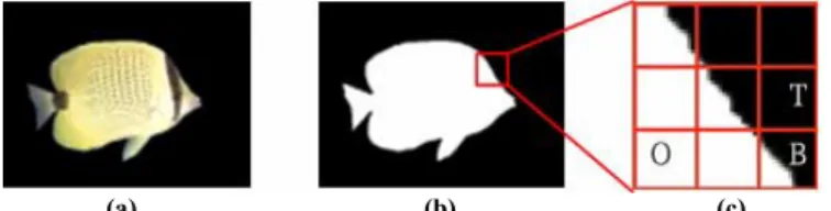
MPEG-4 international standard [1][2] treats moving pictures as an organized collection of visual objects and provides several advanced techniques to access and represent the moving arbitrarily shaped natural and synthetic objects in video scenes. The MPEG-4 visual specifications support several types of visual objects, among which is the video object. The video object may be thought of as a sequence of two-dimensional images. Each image can be associated with shape information to define its shape. As shown in Fig. 1, a video object plane (VOP), which is the instance of a video object at a given time, is composed of a bitmapped alpha component to define the object’s shape and three color
components (YCbCr) to render the object’s texture. Basically, the VOP is defined as a minimum rectangle that encloses the whole object. It is noteworthy that the size of a VOP at a given time depends on the shape of the video object at that time. That is, the size of the VOP for a video object is time-variant. MPEG-4 video encoding is based on the VOP encoder shown in Fig. 2. The alpha component of a VOP is encoded using a binary shape encoder while the color components are encoded using motion estimation and compensation followed by DCT-based texture coding.
Coding the shape information of a VOP takes a few major steps. First, a bounding rectangle is created and extended to multiples of 16×16 pixels with extended alpha samples set to transparency. Next, binary alpha data are grouped with what are called binary alpha blocks (BABs) to have the same dimensions as a macroblock. Finally, shape coding is initiated on a BAB-by-BAB basis.
The encoding of a BAB can be further divided into the following scenarios. First of all, if all the pixels in a BAB are either opaque or transparent, this BAB is a non-boundary BAB and only the coding mode is encoded by means of a variable-length coder (VLC). Second, in interframe, a boundary BAB can be coded with reference to a suitable prediction BAB from the previous coded frame to remove temporal redundancy. This procedure is called binary motion estimation (BME). Based on the assumption that the movement of an object is homogeneous, motion vector of neighboring BAB or texture block is used as the motion vector predictor for shape (MVPs). If the motion compensation (MC) error between the block indicated by the MVPs and current BAB is less than or equal to a predefined threshold, the MVPs is directly employed as motion vector of shape (MVs), and the procedure of BME terminates. Otherwise, full-search block matching is performed around the MVPs within a predefined search range. Each candidate block residing in the search range indicated by a motion vector is compared to the current BAB by computing 16×16 sum of absolute differences
(SADs). The motion vector that minimizes the SADs is taken as MVs. The MVs is further interpreted as motion vector difference for shape (MVDs), i.e., MVDs = MVs − MVPs. In this case, coding mode and MVDs are encoded by shape encoder using VLC. At last, apart from those cases mentioned above, it is generally necessary to employ context-based arithmetic encoding (CAE) to the pixels within a BAB.
There are two CAE operation modes, one is intra-mode and the other is inter-mode. Intra-mode CAE exploits the spatial redundancy by estimating the probability of the current pixel from its neighboring pixels. As for inter-mode, temporal redundancy is exploited by estimating the probability of the current pixel from its neighboring pixels and motion compensated neighboring pixels of the previous coded frame. In intraframe coding, only intra-mode CAE is performed. In interframe coding, both intra- and inter-mode CAE are performed. In both modes, CAE operation is performed pixel by pixel in both horizontal and vertical raster scan order. Therefore, there are total four different coding processes: CAE(Intra, H), CAE(Intra, V), CAE(Inter, H), and CAE(Inter, V). At each
pixel, a template is formed to extract a context number used to access a probability table. The accessed probability and the pixel value are then used to drive an arithmetic encoder. In intraframe coding, the encoded bitstream with minimum size between CAE(Intra, H) and CAE(Intra, V) is chosen as the final
output. Similarly, the encoded bitstream with minimum size among CAE(Intra, H), CAE(Intra, V), CAE(Inter, H), and CAE(Inter, V) is
chosen in interframe coding. In addition, the shape encoder may decide to encode subsampled versions (i.e., lossy coding) of BABs to save encoded bits. If this is the case, the subsampling factor, also known as conversion ratio (CR), is also encoded into the bitstream. The BAB (subsampled or not) then undergoes CAE. Note that CAE itself introduces no additional loss.
In summary, there are seven coding modes for MPEG-4 shape coding in total, as listed in TABLE I. The syntax of the coding mode is represented by bab_type field in the bitstream [1]. The general coding procedure can be as follows.
Step 1: Perform mode decision to determine the current BAB is a boundary or non-boundary one. For a non-boundary BAB, go to Step 5 with bab_type = 2 or 3. For a boundary BAB, go to Step 2 or 3 for interframe or intraframe coding respectively. Step 2: Perform BME. If a qualified motion vector is found, go to step 5 with bab_type = 0 or 1. Otherwise go to Step 3.
TABLE I BABCODING MODES
Coding Mode
(bab_type) Semantic Used in
0 No update && MVDs == 0 P-, B-VOPs 1 No update && MVDs != 0 P-,B-VOPS
2 Transparent I-,P-,B-VOPS
3 Opaque I-, P-,B-VOPS
4 Intra CAE I-,P-,B-VOPS
5 Inter CAE && MVDs == 0 P-,B-VOPS
6 Inter CAE && MVDs != 0 P-,B-VOPS
(a) (b) (c) Fig. 1. Video object plane: (a) Texture component of the VOP. (b) Binary alpha component of the VOP. (c) 16××××16 BABs: O for opaque BAB, T for transparent BAB, and B for boundary BAB.
Shape Coding
Motion
Estimation CompensationMotion TextureCoding Previous Reconstructed VOP + Motion Coding Bitstream VOP Data
enable shape coding
MUX
+ +
Step 3: Perform size conversion to obtain a subsampled version of current BAB. The quality of the subsampled BAB must satisfy the predefined threshold. Go to Step 4.
Step 4: Perform intra-mode CAE for intraframe coding. Perform intra- and inter-mode CAE for interframe coding. Go to Step 5 with bab_type = 4, 5, or 6.
Step 5: Perform VLC for BAB coding mode and other related information.
Fig. 3 shows the block diagram of MPEG-4 binary shape coding system. To improve the performance of the shape encoder, parallel processing of partial or all operations in each step can be implemented.
III. DATA TRANSFER SCHEME
With the ongoing advancements in VLSI technology, the performance of an embedded system is no longer determined primarily by the number and speed of functional units, but by the communication of data among these functional units. Lots of schemes have been used to improve the performance of on-chip communication, including wider data buses, more dedicated channels (buses), more buffers, more advanced bus protocols, more intelligent arbitration schemes, more ingenious schedulings, higher clock rate, etc. The choice of applying single or mixed schemes to improve the performance of on-chip communication are tradeoffs among performance, area, power consumption, hardware utilization, etc. There are several examples of design consideration for these schemes. First, the reasons of using shared-bus architecture instead of multiple dedicated buses are the physical problems and the low utilization of these multiple dedicated buses [14][15]. Second, to keep the internal bus as free as possible, large data buffers, ranging from 384 bytes to 512 bytes, are included in each peripheral attached to this bus [16]. This internal bus is the backbone of an embedded RISC processor-based, real-time multimedia processing system with full motion video processing capabilities, such as MPEG-2 MP@ML decoding. The internal bus is shared by high-performance peripherals, e.g., a Rambus control unit, a DMA control unit, a video control unit, etc. Finally, in order to meet the different bandwidth and latency requirements of the different peripherals attached to the on-chip shared bus of a programmable single chip HDTV processor, the shared bus is controlled via a round-robin arbitration algorithm with programmable bandwidth [17].
In this paper, we present an alternative scheme to improve data transfer performance for shared-bus communication, where the shared bus can be the only bus or one of multiple buses in the target system. The proposed data transfer scheme can keep the shared bus as free as possible by shrinking data transfer amount. In addition, the scheme accelerates the processing of MPEG-4 shape coding by doing the mode decision in Step 1 of shape encoding mentioned in Section II. Moreover, the scheme also speeds up alpha frame memory access, which will be discussed in next section.
The proposed transfer scheme is based on the following three principles. First, simple data transfer scheme is preferred. Too complex scheme may result in not only higher hardware cost but also much latency. Second, the scheme should be independent of any particular bus protocol. Hence, the scheme can be ported easily to different systems. Finally, the worst case performance of the bus sub-system must be at least the same as that without using the proposed scheme. Under these three principles, the proposed data transfer scheme consists of a simple coding, the run-length coding (RLC), and a particular addressing mode.
The run-length coding is chosen under the following considerations. First, video data have one important feature that neighboring pixels have similar values. Although many coding schemes have good performance on dealing with such interpixel redundancy, RLC is considered due to its low complexity. Second, the ability to identify consecutive identical values helps in deciding whether the transferred BAB is a boundary or non-boundary BAB. In our implementation, the value of pixels in a row of a BAB is packed and coded as run, while the length denotes the number of consecutive rows having the same value. If a RLC encoded (run, length) tuple of either (0, 16) or (255, 16) is transferred, the BAB is a non-boundary one since there are 16 consecutive transparent or opaque rows. Otherwise, the transferred BAB is a boundary one. With the helping information from RLC, the coding for a non-boundary BAB only takes three cycles (for Step 5) in our design, while the design in [7] required 23 cycles.
An addressing mode together with RLC compensates the overhead of RLC. In RLC, both the run and the length of run, denoted as length, are needed to be handled. To avoid increasing the width of the data bus for transferring the length, or increasing the total time to transfer both the run and the length, RLC is combined with an addressing mode to make use of available bit information on the address bus. In general, the specification of an on-chip bus would define the minimum memory-mapped space allocated to one slave device to simplify the central address decoder and therefore minimizes the delay of address decoding. For instance, the de facto on-chip bus standard, AMBA, defines that the minimum memory-mapped space for a device is 1K bytes [18]. Although specifications of on-chip buses define the minimum memory-mapped space, most functional units do not need all the assigned memory space. Based on this observation, the length is transferred through some bits of the address bus. As
Mode Decision MVDs Size Conversion Coding Mode Variable Length Coding Context-based Arithmetic Encoding BAB/MCBAB CR Current BAB Binary Motion Estimation Compressed Bitstream Frame Memory Reconstructed BAB Referenced BAB
illustrated in Fig. 4, we encode each BAB with run length coding and then transfer the run through the 16-bit data bus and the length through the address bus. Thus, the value of run is written to different addresses, where the offset of the address depends on the value of length. The length is extracted from the address bus by using memory-mapped address decoding. It’s noteworthy that transferring each opaque or transparent BAB takes only one datum transfer time instead of 16, while in general more than 50% of total BABs are non-boundary.
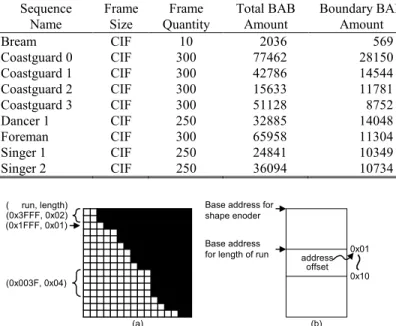
Performance estimation is made by simulation of hardware model written in C/C++ language over the nine test sequences listed in TABLE II. Except for Dancer and Singer, these test sequences are derived from MPEG-4 Video Verification Model [3]. All test sequences are generated for Core Profile at Level 2 with size conversion disabled and shape refresh rate of 1:3. In MPEG-4 Video Verification Model, 8-bit data is used to represent the alpha component of each pixel to indicate either transparent or opaque. For our hardware design, the bi-level alpha data, transparent or opaque, is represented using a single bit. Under the same aforementioned conditions, we define the transfer time ratio (RT) as:
% 100 scheme proposed without ime transfer t scheme proposed with ime transfer t × = T R
The average transfer time ratio over the nine test sequences listed in TABLE II is reduced to 9.39%. The proposed data transfer scheme is also validated in an AMBA AHB subsystem.
IV. FRAME MEMORY DESIGN FOR ALPHA PLANE An efficient frame memory design for alpha plane is essential. As mentioned before, MPEG-4 shape encoder
requires hundred-mega-byte scale memory access per second. In addition, VOP size is changing from time to time while maximum VOP size can be as large as 1920×1088 for Main Profile at Level 4. Hence, we propose a distributed tile-based memory organization for the alpha frame memory that can efficiently conquer the data alignment problem and support variable VOP sizes, while making the address generator more flexible and simple for time-variant VOP sizes. We also propose a low-complexity compression scheme for alpha frame memory to effectively reduce the requirements for memory size and bandwidth.
A. Distributed Tile-Based Memory Organization
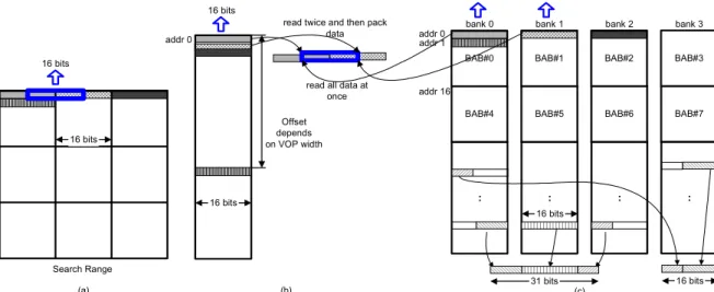
For alpha memory, instead of using traditional linear mapping [7][19], we propose a distributed tile-based mapping which maps each BAB in logic space to a tile in alpha memory in distributed manner. The proposed distributed tile-based mapping out performs linear mapping in the following way. First, tile-based mapping can reduce address bus activity, which in turn leads to low-power memory access [10]. Second, tile-based mapping makes the architecture of the address generator simpler and more flexible for time-varying VOP sizes. Finally, the distributed property helps in accessing data crossing BABs, which is one of the key operations of BME that can significantly affect BME performance. Fig. 5 (a) shows a case of accessing cross-BAB data in the search range of BME.
For MPEG-4’s predecessors, i.e., MPEG-1/2, the frame width is fixed through out the video sequence. Therefore, the memory system can be tuned to pack the right bytes into a word. On the opposite, in MPEG-4 shape encoding, the width of a VOP is changing from time to time, and can be any arbitrary multiples of the width of a BAB. This variation makes the design of memory system for shape encoding more complex.
Tile-based mapping solves parts of the above issue. In our implementation, the tile size is equal to the size of a BAB. Since the bi-level alpha data is represented as 1-bit 0 or 1, one row of data within a BAB, i.e., 16-bit data, is packed as the basic access unit in the alpha plane memory. In addition, the consecutive 16 rows within one BAB are allocated to consecutive memory space. For each write access, only data within a BAB is updated. Therefore, data can be stored to TABLE II
DATA TRANSFER TIME RATIO
Sequence Name Frame Size Frame Quantity Total BAB Amount Boundary BAB Amount Transfer Time Ratio Description
Bream CIF 10 2036 569 11.06 % A swimming fish
Coastguard 0 CIF 300 77462 28150 6.96 % River
Coastguard 1 CIF 300 42786 14544 9.60 % Boat of coastguard
Coastguard 2 CIF 300 15633 11781 10.08 % Skiff
Coastguard 3 CIF 300 51128 8752 3.96 % Coast line
Dancer 1 CIF 250 32885 14048 17.06 % A performance of two dancers
Foreman CIF 300 65958 11304 5.69 % A man who’s talking with body language
Singer 1 CIF 250 24841 10349 15.58 % A singer who’s singing with body language
Singer 2 CIF 250 36094 10734 17.14 % Subtitles that are moving around the singer
Base address for shape enoder Base address
for length of run 0x01
0x10 address offset (0x3FFF, 0x02) (0x1FFF, 0x01) (0x003F, 0x04) ( run, length) (a) (b)
Fig. 4. Proposed data transfer scheme: (a) Run length coding of a BAB. (b) Value of run is written to the corresponding address according to the
consecutive memory addresses without considering the width of the VOP. For read access, it is also likely to read consecutive rows in a BAB. Tile-based mapping also benefits from this locality. In contrast, the address offset of two consecutive rows depends on the VOP width in linear mapping scheme, as displayed in Fig. 5(b). Even worse, the non-consecutive addresses lead to more transitions on the address bus.
To efficiently read data crossing BABs from the alpha frame memory, the alpha frame memory is further distributed into several banks with some constrains:
y For parallel processing of BME using N processing elements (PEs), (16+N-1) bits of reference data are required at each clock cycle. Because these bits might cross several BABs, at least M memory banks are required.
+ + = + + + = otherwise 2 16 1) -(16 1 or 0 16 mod 1) -(16 if 1 16 1) -(16 N N N My M horizontal consecutive BABs in logic space must be stored in the different banks.
In our design, the frame memory includes four banks of 16-bit wide memory and each bank has its dedicated data bus. Although our design has 16 PEs and requires a minimum of three banks, four banks are used for simpler modulo circuits of the address generation. The exact size of each memory bank depends on the maximum size of a VOP to be supported. Pixels in each row of a BAB are packed and stored in one memory entry.
The distributed property leads to some advantages. Most importantly, reading data crossing several BABs may be accessed within a single cycle, as shown in Fig. 5 (c). This advantage removes the requirement of the search range buffer
in [19]. Search range buffer is no longer essential and becomes a tradeoff between the memory access time and silicon area. Besides, when it comes to off-chip memory, the distributed property also applies well. In fact, to store alpha frames into off-chip SDRAM that contains several internal banks, the distributed tile-based memory organization reduces page misses. Consequently, the efficiency of the off-chip memory access and the overall system performance are improved.
B. Compression Scheme for Alpha Frame Memory
Based on the observation that the proportion of boundary BAB is quite low in all the test sequences listed in TABLE II, it is neither efficient nor cost-effective to store these blocks in the alpha frame memory in the raw format. Therefore a low complexity compression scheme for alpha frame memory is proposed by introducing a small index table to keep track of the minimum information of all BABs, while only boundary BABs are stored in the alpha frame memory.
In our compression scheme, the alpha frame buffer contains one alpha frame memory, one index table, and one address generator (AG), as shown in Fig. 6 (a). The alpha frame memory is organized as the one presented in the previous section, except that the relation of one-to-one mapping of BAB from logic VOP space to physical memory space is not maintained. Instead, only boundary BABs are stored in the alpha frame memory. Each BAB in the logic space is assigned a BAB index, while each consecutive 16 words × 16 bits memory space within one memory bank is assigned a tile index. To keep track of all BABs, BAB class (transparent, opaque or boundary) and tile index are stored in the index table, as shown in Fig. 6 (b). An example of how the first two BAB rows at the top of a VOP are stored in the index table and the alpha frame memory is illustrated by Fig. 6 (c).
Before reading the content of a BAB, the index table is read first to decide the BAB class of this BAB by using BAB index as the address of the index table. If a BAB is non-boundary, either opaque or transparent, only the index table is accessed. In contrast,
BAB#0 BAB#1 BAB#2 BAB#3
BAB#4 BAB#5 BAB#6 BAB#7
:::: :::: :::: ::::
bank 0 bank 1 bank 2 bank 3
31 bits 16 bits 16 bits addr 0 addr 16 (a) (b)
read twice and then pack data 16 bits Offset depends on VOP width (c) addr 0 16 bits
read all data at once addr 1 16 bits 16 bits 16 bits 16 bits Search Range
Fig. 5. Memory organization for alpha plane memory. (a) Accessing cross-BAB data in the search range. (b) Linear mapping, single-bank memory organization; Offset between two consecutive rows depends on the width of a VOP. (c) Distributed tile-based memory organization; Capable of accessing data crossing BABs in a single cycle.
if a BAB is a boundary BAB, its affiliated tile index is used to indicate the bank number and the base address of the actual 16×16 BAB data to be read in the alpha frame memory. That is, the LSB two bits of tile index indicate the bank number and the other MSB bits of tile index represent the base address of a boundary BAB in the selected bank by [(tile index >>2) ×16]. As for write accesses, the BAB to be written is classified its BAB class first. For non-boundary BABs, only index table is updated. As for non-boundary BABs, both index table and alpha frame memory must be updated. The size of the index table can be estimated as follows. If the maximum VOP size is 16P×16Q pixels, where P and Q are integers, then the index table has P×Q entries for one alpha plane and each entry has a word length of (1+ log2(P×Q/2) ), where the
ceiling function x gives the smallest integer ≥ x. In addition, P×Q also indicates the maximum BAB number (i.e., the number of BAB index) supported by this index table. For example, the word length of the index table for a 176×144 sized QCIF sequence is (1+ log2(11×9/2) ) = 7 bits, and the memory size of this index table is
7/256 = 2.73% of an alpha frame memory without compression scheme.
The index table does not generally come in a compact size. To support QCIF format, the index table has a size of 693 bits. This small size makes it feasible to implement the index table by using on-chip memory. On the contrary, to support the maximum VOP size of MPEG-4 standard, i.e., 1920×1088 pixels, the index table for an alpha plane is 120×68×(1+ log2(120×68/2)) = 8160×13
bits. Although this size is 5.08% of the original alpha frame memory size, it still occupies considerable area. One approach to further reduce the size of index table is to use multiple segmented index tables such that index tables for small BAB index can have small word length. This approach works because that for a boundary BAB, its tile index stored in the index table is always ascending numbered when its BAB index is ascending numbered, and its tile index is always no greater than its BAB index. For example, index tables for BAB index 0–127, 128–511, 512–2047, and 2048–8160 may have a word length of 7, 9, 11 and 13 bits respectively.
For write access of a boundary BAB, the index table and the
alpha frame memory can be updated at the same time. As for read access, two or three extra clock cycles of latency may be required before random access of the alpha frame memory. However, this latency can be hidden with carefully scheduling of the regular processing flow. The number of memory reference can be roughly estimated as follows. For a non-boundary BAB, no alpha frame memory access is required; only the index table is accessed once. For a boundary BAB, 16 alpha frame memory accesses and one index table access are required. Assume the proportion of non-boundary BAB is PNB, then the proportion of memory access to
both the alpha frame memory and index table is [PNB ×1 + (1-PNB)
×17] / [PNB ×16 + (1-PNB)×16] = 17/16 – PNB. As indicated in
MPEG-4 standard [1], boundary BABs should not exceed 50% of total BABs in a VOP. That is, PNB is no smaller than 0.5.
Consequently, the total memory access for the alpha frame buffer with the index table is about 56.25% of that without using the index table when PNB is 0.5. Furthermore, the restriction that
boundary BABs should not exceed 50% of total BABs in a VOP also guarantees that the alpha frame memory with half size of the maximum VOP works. That is, based on this criterion and the use of the proposed alpha frame buffer architecture, the size of alpha frame memory can be reduced to 50%.
V. CONCLUSIONS
In this paper, an efficient data transfer scheme that significantly reduces the data transfer time to 9.39% has been proposed. The reduced data transfer time can keep the shared system bus as free as possible, which in turn leads to increasing the potentialities of improvement on system performance. Additionally, this data transfer scheme also helps in the processing of mode decision for shape mode coding and BAB class decision for index table access. Therefore, the area cost of this data transfer scheme is alleviated.
We have also presented a distributed tile-based memory organization for the alpha frame memory to efficiently access the required data and support the time-varying VOP sizes. This memory organization makes both the memory access more efficient and the corresponding address generator more simple and flexible. Moreover, we also demonstrated that a small, local index table can
O O O B B T T T T 0 1 2 3 4 5 6 7 8 0 0 0 0 do not care 0 0 do not care 1 1 0 1 do not care 0 1 do not care 0 1 do not care 0 1 do not care 0 1 Address Index Table
Alpha Frame Memory
VOP width O B B B B B T T T 9 10 11 12 13 14 15 16 17 0 1 do not care 1 2 BAB
index BAB#0 BAB#1 BAB#2 BAB#3
BAB#4 BAB#5 BAB#6 BAB#7
bank 0 bank 1 bank 2 bank 3
0 Tile index 4 1 5 2 6 3 7 .. . Alpha Frame Memory Index Table BAB data BAB data BAB class BAB class BAB index 0 O/T 1 Tile index log2(PxQ/2) bits do not care Non-boundary BAB (Opaque/Transparent)
Boundary BAB AG (a) (b) 1 bit 1 bit 1 bit ... ... ... ... (c) Tile index 1 0 3 2 5 4 7 6 8 9 10 do not care
Fig. 6. Compression scheme: (a) Block diagram of the alpha frame buffer. (b) Two formats for each entry of the index table. (c) Relations among a VOP, the index table, and the alpha frame memory.
be used to reduce the number of memory access to the alpha frame memory. In addition, the size of the alpha frame memory, which is much larger and possibly located in an off-chip memory, is decreased to 50% of the original by introducing the index table.
A prototype design of the whole shape encoder with AMBA AHB bus interface is implemented by Verilog RTL design and synthesized with UMC 0.18µm 1P6M CMOS technology [20]. The simulation results show that the system can run at 78.47 MHz to support Main Profile at Level 4. In summary, the proposed data transfer scheme and alpha frame memory design efficiently reduce the system bus bandwidth and the memory requirement of MPEG-4 shape coding.
REFERENCES
[1] ISO/IEC 14496-2, “Information technology — Coding of audio-visual objects,” 2nd edition, Switzerland, Dec. 2001.
[2] N. Brady, “MPEG-4 standardized methods for the compression of arbitrarily shaped video objects,” IEEE Trans. Circuits Syst. Video
Technol., Vol. 9, pp. 1170–1189, Dec. 1999.
[3] ISO/IEC JTC1/SC29/WG11 N3908, MPEG-4 Video Verification Model version 18.0, Jan. 2001.
[4] J. Kneip, S. Bauer, J. Vollmer, B. Schmale, P. Kuhn, and M. Reibmann, “The MPEG-4 video coding standard — A VLSI point of view,” in
Proc. IEEE Workshop Signal Processing Systems Design and Implementation (SiPS’98), pp 43–52, Oct. 1998.
[5] P. M. Kuhn and W. Stechele, “Complexity analysis of the emerging MPEG-4 standard as a basis for VLSI implementation,” Proc. SPIE
Visual Communications and Image Processing (VCIP’98), pp 498–509,
Jan. 1998.
[6] D. Gong and Y. He, “Computation complexity analysis and VLSI architectures of shape coding for MPEG-4,” in Proc. SPIE VCIP’2000, vol. 4067, pp. 1459–1470, Jun. 2000.
[7] H.-C. Chang, Y.-C. Wang, M.-Y. Hsu, and L.-G. Chen, “Efficient algorithms and architectures for MPEG-4 object-based video coding,” in Proc. IEEE Workshop on Signal Processing Systems Design and
Implementation (SiPS 2000), Lafayette, Louisiana, pp 13–22, Oct.
2000.
[8] M. Berekovic, K. Jacob, and P. Pirsch, “Architecture of a hardware module for MPEG-4 shape decoding,” in Proc. Int. Symp. Circuits and
Systems (ISCAS’99), pp. 157–160, May 1999.
[9] J. Thinakaran, D.-J. Ho, and N. Ling, “An architecture for MPEG-4 binary shape decoder,” in Proc. Int. Symp. Circuits and Systems (ISCAS
2000), pp. 457–460, May 2000.
[10] P. R Panda and N. D. Dutt, “Low-power memory mapping through reducing address bus activity,” IEEE Trans. VLSI Syst, Vol. 7, pp. 309– 320, Sept. 1999.
[11] F. Catthoor, F. Franssen, S. Wuytack, L. Nachtergaele, and H. D. Man, “Global communication and memory optimizing transformations for low power signal processing systems,” In VLSI Signal Processing VII, pp. 178–187, 1994.
[12] F. Catthoor, S. Wuytack, E. De Greef, F. Balasa, L. Nachtergaele, and A. Vandecapelle, Custom Memory Management Methodology —
Exploration of Memory Organization for Embedded Multimedia System Design, Kluwer, Boston, 1998.
[13] K. Lahiri, A. Raghunathan, and S. Dey, “Fast performance analysis of bus-based system-on-chip communication architectures,” in Proc. Intl.
Conf. on Computer Aided Design, pp.566-572, San Jose, Nov. 1999.
[14] SOCCreator Guide Design Flow, available on http://www. socworks.com/socworks/support/documentation/html/SOCCreator-Guide-Design-Flow.html
[15] Sonics, Efficient Shared DRAM Subsystems for SOCs, 2001, available on http://www.sonicsinc.com/sonics/products/memmax/productinfo/docs/ DRAM_Scheduler.pdf
[16] K. Suzuki, T. Arai, K. Nadehara, and I. Kuroda, “V830R/AV: Embedded multimedia superscalar RISC processor,” IEEE Micro, pp. 36-47, Mar. 1998.
[17] S. Dutta, “Architecture and design of NX-2700: a programmable single-chip HDTV all-format-decode-and-fisplay processor,” IEEE Trans.
VLSI Syst., pp 313-328, Apr. 2000.
[18] ARM Ltd., “AMBA 2.0 Specification,” 1999.
[19] Y.-C. Wang, H.-C. Chang, W.-M. Chao, and L.-G. Chen, “Efficient architecture of binary motion estimation for MPEG-4 shape coding,” in
Proc. SPIE International Conference on Visual Communications and Image Processing (VCIP 2001), San Jose, California, Jan. 2001.
[20] K.-B. Lee, Nelson Y.-C. Chang, H.-Y. Chin, H.-C. Hsu, and C.-W. Jen “A bandwidth and memory efficient MPEG-4 shape encoder,” to be appeared in ASP-DAC 2004.
Kun-Bin Lee received the B.S. degree in electrical engineering from National Sun Yat-Sen University in 1996, Kaohsiung, Taiwan, and the M.S. degree in electronics engineering from National Chiao Tung University in 1998, Hsinchu, Taiwan. He is currently working on the Ph.D. degree in electronics engineering at National Chiao Tung University. His current research interests include processor architecture, digital signal processing, and system-level exploration with focus on data transfer optimization and memory management for image and video applications. Kun-Bin Lee is a member of Phi Tau Phi.
Hao-Yun Chin received the B.S. degree in electronics engineering from National Chiao Tung University, Hsinchu, Taiwan, R.O.C., in 2002. He is currently working on the M.S. degree in electronics engineering at National Chiao Tung University. His research interests include VLSI design, digital signal processing, and embedded system.
Nelson Yen-Chung Chang received the B.S. degree in electrical engineering from National Tsing-Hua University in 2000, Hsinchu, Taiwan, and the M.S. degree in electronics engineering from National Chiao-Tung University in 2002, Hsinchu, Taiwan. He is currently working on the Ph.D. degree in electronics engineering at National Chiao-Tung University. His current research focus on MPEG-4 related application.
Hui-Cheng Hsu was born in Hsinchu, Taiwan, R.O.C. in 1980. She received the B.S. degrees in electronics engineering from National Chiao Tung University in 2002, Hsinchu, Taiwan. She is currently working on the M.S. degree in electronics engineering at National Chiao Tung University. Her current research interests include VLSI design, digital signal processing, and computer architecture.
Chein-Wei Jen (S'78-M'84) received the BS degree from National Chiao Tung University in 1970, the MS degree from Stanford University, Stanford, California, in 1977, and the Ph.D. degree from National Chiao Tung University in 1983. He is currently with the Department of Electronics Engineering and Institute of Electronics, National Chiao Tung University, Hsinchu, Taiwan, as a professor. During 1985-1986, he was with the University of Southern California, Los Angeles, as a visiting researcher. His current research interests include VLSI design, digital signal processing, processor architecture, and design automation. Dr. Jen is a member of the IEEE and of Phi Tau Phi.