A Low-Cost Wear-Leveling Algorithm
for Block-Mapping Solid-State Disks
∗
Li-Pin Chang
Department of Computer Science, National Chiao-Tung University, Hsin-Chu, Taiwan 300, ROC
Li-Chun Huang
Department of Computer Science, National Chiao-Tung University, Hsin-Chu, Taiwan 300, ROC
Abstract
Multilevel flash memory cells double or even triple storage den-sity, producing affordable solid-state disks for end users. However, flash lifetime is becoming a critical issue in the popularity of solid-state disks. Wear-leveling methods can prevent flash-storage de-vices from prematurely retiring any portions of flash memory. The two practical challenges of wear-leveling design are implementa-tion cost and tuning complexity. This study proposes a new wear-leveling design that features both simplicity and adaptiveness. This design requires no new data structures, but utilizes the intelligence available in sector-translating algorithms. Using an on-line tuning method, this design adaptively tunes itself to reach good balance between wear evenness and overhead. A series of trace-driven sim-ulations show that the proposed design outperforms a competitive existing design in terms of wear evenness and overhead reduction. This study also presents a prototype that proves the feasibility of this wear-leveling design in real solid-state disks.
Categories and Subject Descriptors D.4.2 [Operating Systems]:
Garbage collection; B.3.2 [ Memory Structures]: Mass Storage
General Terms Design, Performance, Algorithm. Keywords Flash memory, wear leveling, solid-state disks.
1. Introduction
Solid-state disks are storage devices that employ solid-state mem-ory like flash as the storage medium. The physical characteris-tics of flash memory differ from those of mechanical hard drives, necessitating different methods for memory accessing. Solid-state disks hide flash memory from host systems by emulating a typi-cal disk geometry, allowing systems to switch from a hard drive to a solid-state disk without modifying existing software and hard-ware. Solid-state disks are superior to traditional hard drives in terms of shock resistance, energy conservation, random-access per-formance, and heat dissipation, attracting vendors to deploy such storage devices in laptops, smart phones, and portable media play-ers.
∗This work is in part supported by research grant NSC-98-2220-E-009-048
from National Science Council, Taiwan, ROC.
Permission to make digital or hard copies of all or part of this work for personal or classroom use is granted without fee provided that copies are not made or distributed for profit or commercial advantage and that copies bear this notice and the full citation on the first page. To copy otherwise, to republish, to post on servers or to redistribute to lists, requires prior specific permission and/or a fee.
LCTES’11, April 11–14, 2011, Chicago, Illinois, USA. Copyright c 2011 ACM 978-1-4503-0555-6/11/04. . . $10.00
Flash memory is a kind of erase-before-write memory. Because any one part of flash memory can only withstand a limited number of erase-write cycles, approximately 100K cycles under the current technology [17], frequent erase operations can prematurely retire a region in flash memory. This limitation affects the lifetime of solid-state disks in applications such as laptops and desktop PCs, which write disks at very high frequencies. Even worse, recent advances in flash manufacturing technologies exaggerate this lifetime issue. In an attempt to break the entry-cost barrier, modern flash devices now use multilevel cells for double or even triple density. Compared to standard single-level-cell flash, multilevel-cell flash degrades the erase endurance by one or two orders of magnitude [18].
Localities of data access inevitably degrade wear evenness in flash. Partially wearing out a piece of flash memory not only de-creases its total effective capacity, but also inde-creases the frequency of its housekeeping activities, which further speeds up the wearing out of the rest of the memory. A solid-state drive ceases to func-tion when the amount of its worn-out space in flash exceeds what the drive can manage. The wear-leveling technique ensures that the entire flash wears evenly, postponing the first appearance of a worn-out memory region. However, wear leveling is not free, as it moves data around in flash to prevent solid-state disks from excessively wearing any one part of the memory. These extra data movements contributes to overall wear.
Wear-leveling algorithms include rules defining when data movement is necessary and where the data to move to/from. These rules monitor wear in the entire flash, and intervene when the flash wear develops unbalanced. Solid-state disks implement wear lev-eling at the firmware level, subjecting wear-levlev-eling algorithms to crucial resource constraints. Prior research explores various wear-leveling designs under such tight resource budgets, revealing three major design challenges: First, monitoring the entire flash’s wear requires considerable time and space overheads, which most con-trollers in present solid-state disks cannot afford. Second, algo-rithm tuning for environment adaption and performance definition requires prior knowledge of flash access patterns, on-line human intervention, or both. Third, high implementation complexity dis-courages firmware programmers from adopting sophisticated wear-leveling algorithms.
Standard solid-state-disk microcontrollers (controllers in the rest of this paper) cannot afford the RAM space overhead required to store the entire flash’s wear information in RAM. Chang et al. [2] proposed caching only portions of wear information. However, periodic synching between the wear information in RAM and in flash introduces extra write traffic to flash. Jung et al. [9] proposed a low-resolution wear information method based on the average wear of large memory regions. Nevertheless, this approach suffers from distortion whenever flash wearing is severely biased. Chang et al. [5] introduced bit-indicated recent wear history. However, recent
wear history blinds wear leveling because recency and frequency are independent in terms of flash wear.
Almost all wear-leveling designs subject wear evenness to tun-able threshold parameters [2, 5, 9]. The system environment in which wear leveling takes place includes many conditions, such as sector-translating algorithms, flash geometry, and host disk work-loads. Even though the wear-leveling threshold remains unchanged, the results of using a wear-leveling algorithm under various sys-tem environments can be very different. Using inadequately tuned parameters can cause unexpectedly high wear-leveling overhead or unsatisfactory wear evenness. Existing approaches require hu-man intervention or prior knowledge of the system environment for threshold tuning.
From a firmware point of view, implementation complexity pri-marily involves the applicability of wear-leveling algorithms. The dual-pool algorithm [2] uses five priority queues of wear infor-mation and a caching method to reduce the RAM footprints of these queues. The group-based algorithm [9] and the static wear-leveling algorithm [5] add extra data structures to maintain coarse-grained wear information and the recent history of flash wear, re-spectively. These approaches ignore the information already avail-able in sector-translating algorithms, which are firmware modules accompanying wear leveling, and unnecessarily increase their de-sign complexity.
This study presents a new wear-leveling design, called the lazy wear-leveling algorithm, to tackle the three design challenges men-tioned above. First, this design does not store wear information in RAM, but leaves all of this information in flash instead. Second, even though this algorithm uses a threshold parameter, it adopts an analytical model to estimate its overhead with respect to different threshold settings, and then automatically selects a good thresh-old for good balance between wear evenness and overhead. Third, the proposed algorithm utilizes the address-mapping information available in the sector-translating algorithms, eliminating the need to add extra data structures for wear leveling.
The rest of this paper is organized as follows: Section 2 reviews flash characteristics and the existing algorithms for sector trans-lating and wear leveling. Section 3 presents the proposed wear-leveling algorithm, and Section 4 describes an adaptive tuning strat-egy for this algorithm. Section 5 reports the results of trace-driven simulations, and Section 6 presents an implementation of the pro-posed algorithm based on a real solid-state disk. Section 7 con-cludes this paper.
2. Problem Formulation
2.1 Flash-Memory CharacteristicsSolid-state disks use NAND-type flash memory (flash memory for short) as a storage medium. A piece of flash memory is a physical array of blocks, and each block contains the same number of pages. In a typical flash geometry, a flash page is 2048 plus 64 bytes. The 2048-byte portion stores user data, while the 64 bytes is a spare area for storing housekeeping data. Flash memory reads and writes in terms of pages, and it must erase a page before overwriting this page. Flash erases in terms of blocks, which consist of 64 pages. Under the current technology, a flash block can sustain a limited number of write-erase cycles before it becomes unreliable. This cycle limit depends on the type of the flash manufacturing technology: a single-level-cell flash block endures 100K cycles [17], while this limit is 10K or less in multilevel-cell flash [18]. The rest of this paper uses terms “flash blocks”, “physical blocks”, or simply “blocks” interchangeably.
Solid-state disks emulate disk geometry using a firmware layer called the flash translation layer (i.e., FTL). FTLs update existing data out of place and invalidate old copies of the data to avoid
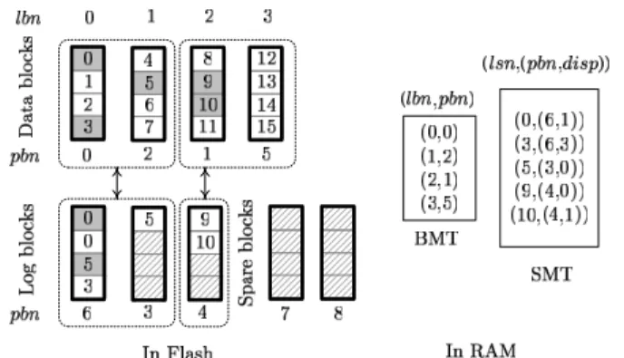
Figure 1. The set-associative mapping scheme whose group size is two. Each data-block group is associated with up to one log-block group.
erasing a flash block every time before rewriting a piece of data. Thus, FTLs require a mapping scheme to translate logical disk-sector numbers into physical locations in flash. Updating data out of place consumes free space in flash, and FTLs must recycle mem-ory space occupied by invalid data with erase operations. Before erasing a block, FTLs copy all valid data from this block to other free space. This series of copy and erase operations for reclaiming free space is called garbage collection. Reducing data-copy over-head during garbage collection is a priority in FTL designs. 2.2 Flash Translation Layers
FTLs are part of the firmware in solid-state disks. They use RAM-resident index structures to translate logical sector numbers into physical flash locations. Mapping resolutions have direct impact on RAM-space requirements and write performance. Block-level mapping [21], adopted in many entry-level flash-storage devices like USB thumb drives, requires only small mapping structures. However, low-resolution mapping suffers from slow response when servicing non-sequential write patterns. Sector-level mapping [3,6, 7] better handles random write requests, but requires large mapping structures, making its implementation infeasible in high-capacity solid-state disks.
Hybrid mapping combines both sector and block mapping for good balance between RAM-space requirements and write perfor-mance. This method groups consecutive logical sectors as logical blocks as large as physical blocks. It maps logical blocks to phys-ical blocks on a one-to-one basis using a block mapping table. If a physical block is mapped to a logical block, then this physical block is called the data block of this logical block. Any unmapped physical blocks are spare blocks. Hybrid mapping uses spare blocks as log blocks to serve new write requests, and uses a sector map-ping table to redirect read requests to the newest versions of data in spare blocks.
Hybrid mapping requires two policies: the first policy forms groups of data blocks and groups of log blocks, and the second policy associates these two kinds of groups with each other. Figures 1and 2 show two FTL designs that use different policies. Let lbnand pbn stand for a logical-block number and a physical-block number, respectively. The term lsn represents a logical-sector number, and disp is the page offset in a physical block. The bold boxes stand for physical blocks, each of which has four pages. The number in the pages indicate the lsns of their storage data. White pages, shadowed pages, and pages with diagonal lines represent pages containing valid data, invalid data, and free space, respectively. The BMT and the SMT are the block mapping table and the sector mapping table, respectively.
Figure 2. The fully-associative mapping scheme. All data blocks are in one group and all log blocks are in the other.
Let the group size denote the number of blocks in a group. In Fig.1, the group size of data blocks is exactly two, while the group size of log blocks is no larger than two. This mapping scheme, called set-associative mapping, associates a data-block group with one log-block group or none. This design has two important vari-ants: set-associative sector translation (SAST), developed by Park et al. [15], and block-associative sector translation (BAST), de-veloped by Chung et al. [22]. SAST uses two variables, N and K, to set the group sizes of data blocks and log blocks, respec-tively. BAST (Block-Associative Sector Translation) [22] is sim-pler, fixing N=1 and K=1 always. Figure2depicts another map-ping scheme, called fully-associative mapmap-ping. This method has only two groups associated with each other, one for all data blocks and the other for all log blocks. Fully-associative sector translation (FAST), developed by Lee et al. [12], is based on this design. 2.3 The Need for Wear Leveling
FTLs write new data in log blocks allocated from spare blocks. When they run low on spare blocks, FTLs start erasing log blocks. Before erasing a log block, FTLs collect the valid data from the log block and from the data block associated with this log block, copy this valid data to a blank block, remove the sector-mapping information related to the log block, re-direct block-mapping in-formation to the copy destination block, and finally erase the old data block and log block into spare blocks. This procedure is called either merging operations or garbage collection.
For example, in Fig. 1, the FTL decides to erase the group consisting of log blocks at pbns 3 and 6. This log-block group is associated with the group of data blocks at pbns 0 and 2. The FTL prepares a group of two blank blocks at pbns at 7 and 8. Next, the FTL collects four valid sectors at lsns 0 through 3, and writes them to the blank block at pbn 7. Similarly, the FTL copies valid sectors at lsns 4 through 7 to the blank block at pbn 8. Finally, the FTL erases the physical blocks at pbns 0, 2, 3, and 6 into spare blocks, and then re-maps lbns 0 and 1 to physical blocks at pbns 7 and 8, respectively.
Log-block-based FTLs exhibit some common behaviors in the garbage-collection process regardless of their grouping and associ-ating policies. FTLs never erase a data block if none of its sector data have been updated. In the set-associative mapping illustration in Fig.1, erasing the data blocks at pbn 5 does not reclaim any free space. Similarly, in the fully-associative mapping illustration in Fig.2, erasing any of the log blocks does not involve the data block at pbn 5. This is a potential cause of uneven flash wear.
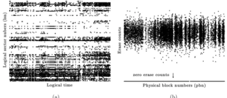
Figure3(a) shows a fragment of the disk-write traces recorded from a laptop PC’s daily use1. The X-axis and the Y-axis of this
1This workload is the NOTEBOOK workload in Section5.1.
Figure 3. Flash wear in a solid-state disk under the disk workload of a laptop. (a) A fragment of the disk-write workload and (b) the final distribution of flash blocks’ erase counts.
figure represent the logical time and the lsns of write requests, re-spectively. This pattern biases write requests toward a small collec-tion of disk sectors. Let a physical block’s erase count denote how many write-erase cycles this block has undergone. After replay-ing the trace set on a real solid-state disk which adopts an FAST-based FTL (Section6.1describes this product in more detail), Fig. 3(b) shows that the final distribution of erase counts is severely un-balanced. The X-axis and Y-axis of Fig.3(b) represent the pbns and erase counts of physical blocks, respectively. Nearly 60% of all physical blocks have zero erase counts, as the horizontal line at the bottom of Fig.3(b) shows. In other words, this workload retires only 40% of all blocks, while the rest remain fresh. Evenly dis-tributing erase operations can double the flash lifespan compared to that without wear leveling.
2.4 Prior Wear-Leveling Strategies
This section provides a conceptual overview of existing wear-leveling designs. Static wear wear-leveling moves static/immutable data away from lesser worn flash blocks, encouraging FTLs to start eras-ing these blocks. Flash vendors includeras-ing Numonyx [14], Micron [13], and Spansion [20] suggest using static wear leveling for flash lifetime enhancement. Chang et al. [5] described a static wear lev-eling design, and later Chang et al. [2] showed that this design is competitive with existing approaches. However, the experiments in this study reveal that static wear leveling suffers from uneven flash wear on the long-term.
Hot-cold swapping exchanges data in a lesser worn block with data from a badly worn block. Jung et al. [9] presented a hot-cold swapping design. However, Chang et al. [2] showed that hot-cold swapping risks erasing the most worn flash block pathologically. Cold-data migration relocates immutable data to excessively worn blocks and then isolates these worn blocks from wear leveling until they are no longer worn blocks compared to other blocks. Chang et al. [2] described a design of this idea. This design adopts five priority queues to sort blocks in terms of their wear information and a cache mechanism to store only frequently accessed wear lev-eling. However, synching the wear information between the cache and flash introduces extra write traffic to flash, and its higher im-plementation complexity may be a concern of firmware designers.
Unlike the wear-leveling designs above that treat wear leveling and garbage collection as independent activities, Chiang et al. [6] and Kim et al. [11] proposed heuristic functions that score flash blocks with considering garbage collection and wear leveling. In this case, FTLs erase the most scored block. However, erasing a block can require re-scoring all flash blocks. This task excessively stress the controllers and delay ordinary read/write requests.
There are compromises between algorithm concept and im-plementation, because the controllers can offer very limited re-sources. Even though different wear-leveling designs are based on
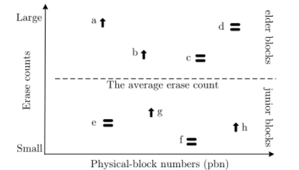
Figure 4. Physical blocks and their erase recency and erase counts. An upward arrow indicates that a block has recently increased its erase count.
the same concept, they could have very different resource demands and performance characteristics. For example, among the differ-ent designs of static wear leveling, Chang et al. [5] proposed us-ing a periodically-refreshed bitmap to indicate not recently erased blocks. Differently, the designs from Numonyx [14] and Chang and Kuo [4] store blocks’ erase counts in RAM, and involve the block of the smallest erase count in wear leveling.
Lazy wear leveling (the proposed approach) roots in cold-data migration. However, different from the dual-pool algorithm [2], which is also based on cold-data migration, lazy wear leveling adopts the following innovative designs. First, lazy wear leveling does not store blocks’ wear information in RAM. It leaves them in flash instead, and utilizes the mapping information available in FTLs to assist wear leveling. In contrast, the dual-pool algorithm requires RAM space to store blocks’ wear information and monitor them constantly. Caching the frequently referenced wear informa-tion helps to reduce the RAM requirements, but synching wear in-formation between the cache and RAM can add up to 10% of extra write traffic to flash [2]. The second new idea in lazy wear level-ing is the ability of self tunlevel-ing. Wear-levellevel-ing algorithms subject wear evenness to a threshold parameter. However, the overhead of wear leveling grows at different rates under different system envi-ronments when changing the threshold value. Lazy wear leveling characterizes the overhead as a function of the threshold values, and adaptively tunes the threshold for good balance between the overhead and wear evenness.
3. A Low-Cost Wear-Leveling Algorithm for
Block-Mapping FTLs
3.1 Observations
Let the update recency of a logical block denote the time length since the latest update to this logical block. If a logical block’s last update is more recent than the average update recency, then this logical block’s update recency is high. Otherwise, its update recency is low. Analogously, let the erase recency of a physical block be the time length since the latest erase operation on this block. Thus, immediately after garbage collection erases a physical block, this block has the highest erase recency among all blocks. A physical block is an elder block if its erase count is larger than the average erase count. Otherwise, it is a junior block. Notice that block seniority is a relative measure. For example, even though all blocks in a brand-new flash have small erase counts, there will be some elder blocks and junior blocks.
FTLs avoids erasing flash blocks mapped to unmodified logical blocks, because erasing these flash blocks reclaims no free space. Thus, the temporal localities of writing disk sectors can translate into temporal localities of erasing physical blocks. If a flash block
has a high erase recency, then this block was not mapped to a static logical block. This flash block will then be mapped to a recently modified logical block. Because of temporal localities of writing disk sectors, recently modified logical blocks will be frequently modified. Therefore, the flash block will be mapped to mutable logical blocks and frequently increases its erase count. Conversely, a physical block loses momentum in increasing its erase count if its erase recency is low.
Figure4provides an example of eight physical blocks’ erase re-cency and erase counts. Upward arrows mark physical blocks cur-rently increasing their erase counts, while an equal sign indicates otherwise. Block a is an elder block with a high erase recency, while block d is an elder but has a low erase recency. The junior block h has a high erase recency, while the erase recency of the junior block e is low.
A block should keep its erase count close to the average. For instance, the junior blocks g and h are increasing their erase counts toward the average, while the difference between the average and the erase counts of the elder blocks c and d is decreasing. However, other than the above two cases, block wear can require intervention from wear leveling. First, the junior blocks e and f have not recently increased their erase counts. As their erase counts fall below the av-erage, wear leveling has them start participating in garbage collec-tion. Second, the elder blocks a and b are still increasing their erase counts. Wear leveling should have garbage collection stop further wear in these two elder blocks.
3.2 The Lazy Wear-Leveling Algorithm
This study proposes a new wear-leveling algorithm based on a sim-ple princisim-ple: whenever any elder blocks’ erase recency becomes high, the algorithm re-locates (i.e., re-maps) logical blocks with a low update recency to these elder blocks. This algorithm, called the lazy wear-leveling algorithm, is named after its passive reaction to unbalanced flash wear.
Lazy wear leveling focuses on the wear of elder blocks only, because elder blocks retire before junior blocks. Thus, being aware of recent wear of elder blocks is important. Physical blocks boost their erase recency only when the FTL erases them for garbage col-lection. Thus, if the FTL notifies lazy wear leveling of its decision on the next victim block, lazy wear leveling can check this victim block’s seniority. This way, lazy wear leveling needs not repeatedly check all elder blocks’ wear information.
How to prevent elder blocks from further aging is closely related to garbage-collection behaviors: Garbage collection has no interest in erasing a data block if this data block is not associated with any log blocks. A data block does not require any log blocks for storing new updates if the logical block mapped to this data block has a low update recency. Because recent sector updates to a logical block leaves mapping information in the FTL’s sector-mapping table, lazy wear leveling selects logical blocks not related to any sector-mapping information as logical blocks with a low update recency. The logical block at lbn 3 in Fig.1and2is such an example.
Re-mapping logical blocks with a low update recency to elder blocks can prevent elder blocks from wearing further. To re-map a logical block from one physical block to another, lazy wear lev-eling moves all valid data from the source physical block to the destination physical block. This invalidates all data in the source block and directs the upcoming garbage-collection activities to the source block. Junior blocks are the most common kind of source blocks, e.g., blocks e and f in Fig.4, because the storage of im-mutable data keeps them away from garbage collection. Therefore, selecting logical blocks for re-mapping is related to the wear of junior blocks. To give junior blocks an even chance of wear, it is important to uniformly visit every logical block when selecting a logical block for re-mapping.
Algorithm 1 The lazy wear-leveling algorithm
Input: v: the victim block for garbage collection Output: p: a substitute for the original victim block v
1: ev←eraseCount(v) 2: if (ev− eavg) > Δthen 3: repeat 4: l← lbnNext() 5: until lbnHasSectorMapping(l)=FALSE 6: erase(v); 7: p← pbn(l) 8: copy(v, p); map(v, l) 9: ev← ev+ 1
10: eavg← updateAverage(eavg, ev)
11: else 12: p← v 13: end if 14: RETURN p
The temporal localities of write requests can change occasion-ally. Disk workloads can start updating a logical block which pviously had a low update recency. If this logical block was re-cently re-mapped to an elder block for wear leveling, then the new updates neutralize the prior re-mapping operation. However, lazy wear leveling will perform another re-mapping operation for this elder block when the FTL is about to erase this elder block again. 3.3 Interaction with FTLs
This section describes how lazy wear leveling interacts with its accompanying firmware module, the flash translation layer. Lazy wear leveling and the FTL operate independently, but the FTL pro-vides some information to assist wear leveling. Algorithm1shows the pseudo code of the lazy wear-leveling algorithm. The FTL in-vokes this procedure every time it erases a victim block for garbage collection. This procedure determines if wear leveling needs inter-vene in the erasure of the victim block. If so, this procedure looks for a logical block that has not been updated recently, re-maps this logical block to the victim block, and then selects the physical block previously mapped to this logical block as a substitution for the original victim block. Notice that the FTL needs not consider wear leveling when selecting victim blocks. In other words, lazy wear leveling is independent of the FTL’s victim-selection policy.
In Algorithm1, the FTL provides the subroutines with leading underscores, and wear leveling implements the rest. The algorithm input is v, the victim block’s physical block number. Step 1 obtains the erase count evof the victim block v using eraseCount(). Step
2 compares evagainst the average erase count eavg. If evis larger
than eavg by a predefined threshold Δ, then Steps 3 through 10
will carry out a re-mapping operation. Otherwise, Steps 12 and 14 return the original victim block to the FTL intact.
Steps 3 through 5 find a logical block with a low update re-cency. Step 4 uses the subroutine lbnNext() to obtain l the next logical block number to visit, and Step 5 calls the subroutine lbnHasSectorM apping()to check if the logical block l has any related mapping information in the FTL’s sector-mapping ta-ble. These steps cycle through all logical blocks until they find a logical block not related to any sector-mapping information. As mentioned previously, to give all junior blocks (which are related to logical blocks with a low update recency) an equal chance to get erased, the subroutine lbnNext() must evenly visit all logical blocks. The implementation of lbnNext() can be any permuta-tions of all logical block numbers, such as the Linear Congruential Generator [16]. Using permutations also maximizes the interval between two consecutive visits to the same logical blocks, reduc-ing the probability of re-mappreduc-ing a logical block with a low update recency from an elder block to another.
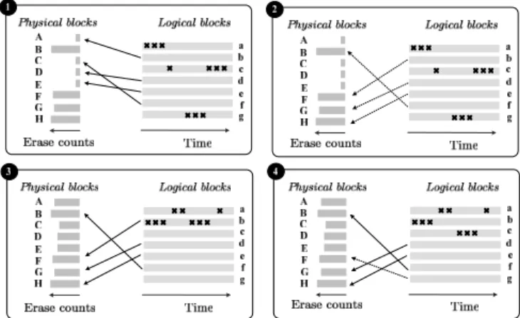
Figure 5. A scenario of running the lazy wear-leveling algorithm. Crosses indicate write requests to logical blocks.
Steps 6 through 8 re-map the previously found logical block l. Step 6 erases the original victim block v. Step 7 uses the subroutine pbn() to identify the physical block p that the logical block l currently maps to. Step 8 copies the data of the logical block l from the physical block p to the original victim block v, and then re-maps the logical block l to the former victim block v using the subroutine map(). After this re-mapping, Step 9 increases evsince the former
victim block v has been erased, and Step 10 updates the average erase count. Step 14 returns the physical block p, which the logical block l previously mapped to, to the FTL as a substitute for the original victim block v.
3.4 Algorithm Demonstration
Figure5shows a four-step scenario of using the lazy wear-leveling algorithm. In each step, the left-hand side depicts the physical blocks and their erase counts, and the right-hand side shows the logical blocks and their updates marked with bold crosses. This example shows only the mapping of logical blocks with a low update recency to elder physical blocks.
Step 1 shows the initial condition. Let the erase counts of the elder physical blocks B, F, G, and H be greater than the average by Δ. Step 2 shows that lazy wear leveling re-maps logical blocks of a low update recency f, b, d, and e to elder physical blocks B, F, G, and H, respectively. As garbage collection avoids erasing physical block with no invalid data, Step 3 shows that physical blocks other than B, F, G, and H increase their erase counts, after processing a new batch of write requests. In this case, the wear of all blocks is becoming even.
In Step 3, the write pattern generates several updates to the logical block b. However, previously in Steps 1 and 2, this logical block had a low update recency, and wear leveling already re-mapped it to the elder physical block F. As previously mentioned in Section3.2, these new updates to the logical block b will cause further wear of the elder physical block F, making the prior re-mapping operation of the logical block b ineffective in terms of wear leveling. Step 4 shows that lazy wear leveling re-maps another logical block g with a low update recency to the elder physical block F as soon as it learns that the FTL is about to erase the elder physical block F.
4. Adaptive Self Tuning
Tuning the threshold parameter Δ helps lazy wear leveling to achieve good balance between overhead and wear evenness. This tuning strategy consists of two parts: Section4.1presents an ana-lytical model of the overhead and wear evenness of wear leveling.
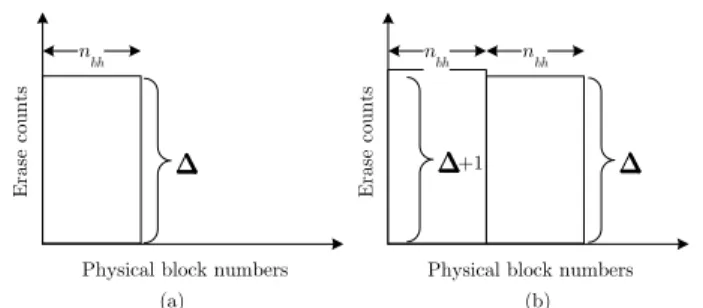
Figure 6. Erase counts of flash blocks right before the lazy wear-leveling algorithm performs (a) the first re-mapping operation and (b) the nbh+1-th re-mapping operation.
Section4.2introduces an on-line algorithm that adjusts Δ based on the analytical model.
4.1 Performance Analysis: Overhead and Wear Evenness Consider a piece of flash memory consisting of nbphysical blocks.
Let immutable logical blocks map to nbc among all physical
blocks. Let the sizes of write requests be multiples of the block size. Let write requests be aligned to block boundaries. Suppose that the disk workload uniformly writes the mutable logical blocks. Thus, the FTL evenly increases the erase counts of the nbh=nb− nbc
physical blocks.
Let the function f(x) denote how many blocks garbage collec-tion erases to process a workload writing x logical blocks. Consider the case x = i × nbh× Δ, where i isa non-negative integer. As all
request sizes are multiples of the block size and requests are block-aligned, erasing victim blocks does not cost garbage collection any overhead in copying data. Thus, without wear leveling, we have
f (x) = x.
Now, consider wear leveling enabled. For ease of presentation, this simulation revises the lazy wear leveling algorithm slightly: instead of comparing the victim block’s erase count to the aver-age erase count, the algorithm compares it against the smallest among all blocks’ erase counts. Figure6(a) shows that, right before lazy wear leveling performs the first re-mapping, garbage collection has uniformly accumulated nbh× Δ erasecounts in nbhphysical
blocks. In the subsequent nbherase operations, garbage collection
erases each of these nbh physical blocks one more time, and
in-creases their erase counts to Δ + 1. Thus, lazy wear leveling con-ducts nbh re-mapping operations for these physical blocks at the
cost of erasing nbhblocks. These re-mapping operations re-direct
garbage-collection activities to another nbhphysical blocks.
Simi-larly, Fig.6(b) shows that, after garbage collection accumulates an-other nbh× Δ erase counts in these new nbhphysical blocks, lazy
wear leveling again spends nbh erase operations for re-mapping
operations. Let function f0(x)be analogous to f(x), but with wear
leveling enabled. We have f0(x) = x +j x
Δ k
= x + i× nbh.
Under real-life workloads, the frequencies of erasing these nbh
blocks may not be uniform. Thus, f0(x)adopts a coefficient K
to take this into account:
f0(x) = x + i× nbh× K.
The coefficient K depends on various system conditions, such as flash geometry, host workloads, and FTL algorithms. For exam-ple, dynamic changes in temporal write localities can increase K because the write pattern might start updating the logical blocks which wear leveling has previously used for re-mapping.
Let the overhead function g(Δ) denote the overhead ratio with respect to Δ: g(Δ) =f0(x)− f(x) f (x) = i× nbh× K i× nbh× Δ = K Δ. Because lazy wear leveling compares victim blocks’ erase counts against the average erase count rather than the smallest erase count, we use 2Δ as an approximation of the original Δ, and have the co-efficient K include the compensation for the error in the approxi-mation. Thus, we have
g(Δ) = K
2Δ. (1)
Notice that, when Δ is small, a further decrease in Δ rapidly increases the overhead ratio. For example, decreasing Δ from 4 to 2 doubles the overhead ratio.
Next, let us focus on the relation between Δ and the wear even-ness in flash. Let the metric of the wear eveneven-ness be the standard de-viation of all blocks’ erase counts, i.e.,q1
nb Pnb
i=1(ebi− eavg)2. The smaller the standard deviation is, the more even the wear of flash blocks is. Provided that wear leveling is successful, Pnb
i=1(ebi − eavg)
2 would be bounded by n
b× Δ2. Thus, the
relation between the wear evenness and Δ would be bounded by a linear relation.
4.2 On-Line Δ Tuning
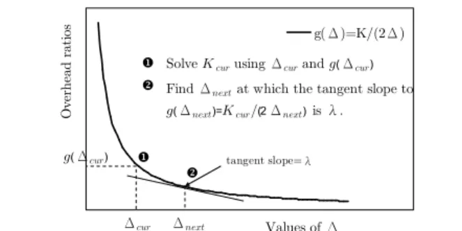
As the wear evenness is linearly related to Δ, small Δ values are always preferred in terms of wear evenness. Differently, the relation between the overhead and Δ is non-linear, and decreasing Δ value can cause an unexpectedly large overhead increase. Thus, in spite of limiting the total overhead, setting Δ should consider whether the overhead is worth the wear evenness. This section presents an on-line algorithm that dynamically tunes Δ for balance between overhead and wear evenness. Because there are simple means to limit the total overhead such as adjusting the duty cycle of wear leveling, this study focuses on limiting the overhead growth rate when tuning Δ.
Under dynamic disk workloads, the coefficient K in g(Δ) may vary over time. Thus, wear leveling must first determine the coef-ficient K before using g(Δ) for Δ-tuning. This study proposes a session-based method for Δ-tuning. A session refers to a time in-terval in which lazy wear leveling contributed a pre-defined number of erase counts. This number is the session length. The basic idea is to compute Kcurof the current session and use this coefficient
to find Δnextfor the next session.
The first session adopts Δ=16, but in theory this initial Δ value can be any number because it will not affect K. Let the current session adopts Δcur. Figure 7illustrates the concept of the
Δ-tuning procedure: during a runtime session, lazy wear leveling records the erase counts contributed by the garbage collection and wear leveling. At the end of the current session, the first step (in Fig.7) computes the overhead ratio f0(x)−f(x)
f (x) , i.e., g(Δcur), and
solves Kcurof the current session using Equation1, i.e., Kcur=
2Δcur× g(Δcur).
The second step uses g(Δnext)=Kcur/(2Δnext)to find Δnext
for the next session. Basically, lazy wear leveling minimizes Δ values subject to a user-defined limit λ on the growth rate of the overhead ratio (when decreasing Δ). Let the unit of the overhead ratio be one percent. For example, λ=-0.1 means that the overhead ratio increases from x% to (x+0.1)% when decreasing Δ from y to (y-1). Solve d
dΔg(Δnext) = λ
100 for the smallest Δ value subject
to λ. Rewriting this equation, we have Δnext= r 100 −λ p g(Δcur)Δcur.
Figure 7. Computing Δnextsubject to the overhead growth limit
λfor the next session according to Δcurand the overhead ratio
g(Δcur)of the current session.
For example, when λ=-0.1, if the overhead ratio g(Δcur)and Δcur
of the current session are 2.1% and 16, respectively, then Δnextfor
the next session isq100 0.1
√
2.1%× 16 = 18.3.
The Δ-tuning method adjusts Δ on a session-by-session basis. It requires the session length as the period of adjusting Δ, and λ as a user-defined boundary between linear and super-linear over-head growth rates. The later experiments show that λ=-0.1 is a rea-sonably good setting, and wear-leveling results are insensitive to different session lengths.
5. Performance Evaluation
5.1 Experimental Setup and Performance Metrics
We built a solid-state disk simulator using System C [8]. This sim-ulator includes a flash module for behavioral simulation on read, write, and erase operations. This flash module can also accept dif-ferent geometry settings. Based on this flash module, the simulator implements different FTL algorithms, including BAST [22], SAST [15], and FAST [12], which are representative designs at the current time. We tailored the lazy wear-leveling algorithm to accompany each of the FTL algorithm. This simulator also includes the static wear-leveling algorithm based on Chang’s design [5]. Static wear leveling is widely used in industry [13,14,20] and has been proven competitive with existing wear-leveling algorithms [2].
The input of the simulator is a series disk requests, ordered chronologically. These disk requests were recorded from four types of real-life host systems: a Windows-based laptop, a desktop PC running Windows, a Ubuntu Linux desktop PC, and a portable me-dia player. The user activities of the laptop and desktop workloads include web surfing, word processing, video playback, and gam-ing, while those of the media player workload are to copy, play, and delete MP3 and video files. These choices include popular op-tions of operating systems (e.g., Linux or Windows), file systems (e.g., ext4 or NTFS), hard-drive capacity, and system usages (e.g., mobile or desktop). Table1describes the four disk workloads.
This study adopts two major performance metrics for flash-wear evenness and wear-leveling overhead. The standard deviation of all flash blocks’ erase counts (the standard deviation for short) indicates the wear evenness in the entire flash. The smaller the standard deviation is, the more level is the wear in flash. The mean of all flash blocks’ erase counts (the mean for short) is the arithmetic average of all blocks’ erase counts. The difference between the means of with and without wear leveling reveals the overhead of wear leveling in terms of erase operations. The smaller the mean increase is, the lower is the wear-leveling overhead. It is desirable to achieve both a small standard deviation and a small mean increase.
Unless explicitly specified, all experiments adopted the follow-ing default settfollow-ings: The threshold parameters Δ and TH of lazy
Workload Operating Volume File Total system size system written Notebook Windows XP 20 GB NTFS 27 Desktop 1 Windows XP 40 GB NTFS 81 Desktop 2 Ubuntu 9 40 GB ext4 55 Multimedia Windows CE 20 GB FAT32 20 GB Table 1. The four experimental workloads.
Figure 8. Evaluating lazy wear leveling and static wear leveling with FTL algorithms BAST, SAST, and FAST under the notebook disk workload.
wear leveling and static wear leveling were both 16. TH refers to the ratio of the total erase count to the total number of re-cently erased flash blocks (i.e., the blocks indicated as one in the erase bitmap). Dynamic Δ tuning will be evaluated in Section5.3. The flash page size and block size were 4KB and 512KB, respec-tively, reflecting a typical geometry of MLC flash [18]. The in-put disk workload was the notebook workload, and the FTL al-gorithm was FAST [12]. The sizes of the logical disk volume and the physical flash were 20GB and 20.5GB, respectively. Thus, the over-provisioning ratio was (20.5-20)/20=2.5%. The experiments replayed the input workload one hundred times to accumulate suffi-ciently many erase cycles in flash blocks. This helped to differenti-ate the efficacy of different wear-leveling algorithms. These replays did not manipulate the experiments. Provided that wear leveling is effective, replaying the input disk workload once sufficiently erases the entire flash one time.
5.2 Experimental Results
5.2.1 Effects of Using Different FTL Algorithms
Figure8shows the results of using BAST, SAST, and FAST with lazy wear leveling and static wear leveling. The Y-axes of Fig.8(a) and8(b) indicate the standard deviations and the means, respec-tively. First consider the results without using wear leveling. These results show that FAST achieved the smallest mean among the three FTL algorithms. This is because FAST fully utilizes free space in every log bock [12]. On the contrary, BAST suffered from very high garbage-collection overheads, because BAST has poor space utilization in log blocks. These observations agreed with that re-ported in prior work [12,15,22].
Lazy wear leveling consistently delivered low standard devia-tions under the three FTL algorithms. Its standard deviadevia-tions were between 10 and 12, almost not affected by FTL algorithms. In con-trast, static wear leveling’s standard deviations were much larger than that of lazy wear leveling, and was very sensitive to the use of different FTL algorithms. In particular, its standard deviations were 137 and 66 under BAST and FAST, respectively. Regarding wear-leveling overhead, the mean increase of lazy wear wear-leveling was very small, which was no more than 3% in all experiments. Static wear leveling’s mean increase was slightly larger, reaching 6%.
Figure 8(b) shows that when the FTL algorithm was SAST, lazy wear leveling introduced a slightly larger mean increase than
Figure 9. Experimental results of using lazy wear leveling and static wear leveling under the four types of disk workloads. static wear leveling. This is due to the different definitions of the threshold parameters of lazy wear leveling and static wear leveling. For a fair comparison, we set Δ = 18 and TH = 16 such that the two wear-leveling algorithms produced the same mean increase. Under these settings, the standard deviations of lazy wear leveling was 18, which was much better than 107 in static wear leveling. Section5.4provides explanations of the large standard deviation of static wear leveling.
5.2.2 Effects of Using Different Host Workloads
This part of the experiment evaluated wear-leveling algorithms under the four types of disk workloads (as Table1shows). The number of times each of the four workload replays was subject to a constant ratio of the total amount of data written into the disk to the logical disk volume size. This ratio was determined by replaying the notebook workload 100 times, i.e., (100×27GB)/20GB=135.
Figure 9 shows that, without wear leveling, the multimedia workload had the smallest mean and standard deviation among the four workloads. This workload consisted of plenty of large and sequential write requests that accessed almost the entire disk space. Therefore garbage collection incurred mild overhead and accumulated erase cycles in all flash blocks at nearly the same rate. On the other hand, the standard deviations and means of using the notebook workload and the two desktop workloads were large. This is because these disk workloads consisted of temporal localities, which amplified the garbage-collection overhead and biased the flash wear as well.
Figure9shows that, regardless of the disk workload adopted, lazy wear leveling successfully lowered the standard deviations to about 10. Lazy wear leveling caused only marginal mean increase, no more than 3% under all workloads. On the other hand, even though static wear leveling’s increases on the mean were compara-ble to that of lazy wear leveling, its large standard deviations indi-cate that it failed to balance the flash wear in all workloads. 5.2.3 Flash Geometry and Over-Provisioning Ratios
Flash geometry and over-provisioning ratios directly affect garbage-collection overhead and the wear evenness in flash. This experi-ment has two parts. The first part considered three kinds of flash geometry of page size/block size: 2KB/128KB, 4KB/512KB, and 4KB/2MB. The first and the second setups were typical geome-tries of SLC flash [17] and MLC flash [18], respectively. Advanced architecture designs employ multiple channels for parallel access over multiple flash chips [1,10,19]. Thus, the third setting cor-responds to the effective geometry of a four-channel architecture. The results in Fig.10show that, without wear leveling, adopting coarse-grained flash geometry not only increased the overhead of garbage collection but also degraded the evenness of flash wear. When using lazy wear leveling, the standard deviations and the mean increases were both small. This advantage remained whether the flash geometry was coarse-grained or fined-grained.
Figure 10. Experimental results under different settings of flash geometry.
Figure 11. Experimental results under different over-provisioning ratios of flash memory.
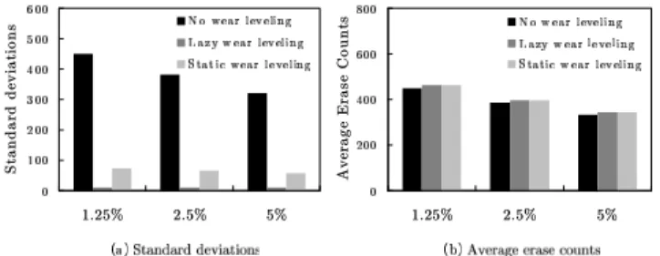
The second part of this experiment adopted three over-provisioning ratios: 1.25%, 2.5%, and 5%. The smaller the over-provisioning ra-tio is, the fewer log blocks the FTL can have. Figure11indicates that using small over-provisioning ratios resulted in high overhead of garbage collection. This is because the demand for free space forced the FTL to prematurely copy valid data for garbage col-lection before these valid data might be invalidated by new write request. Amplified garbage-collection activities also increased the wear unevenness in flash. When using lazy wear leveling, the stan-dard deviations and the mean increases were again small, and its performance was not significantly affected by using different over-provisioning ratios.
5.3 Automated Δ-tuning
This experiment adopted two system configurations C1 and C2:
the configuration C1used the Linux desktop workload with BAST,
while the configuration C2 adopted the notebook workload with
FAST. The flash geometry was in both C1 and C2 were both
4KB/2MB. The over-provisioning ratios of C1and C2were 1.25%
and 0.625%, respectively.
This experiment consists of three parts. The first part reports the overhead and the standard deviation with respect to different static Δsettings (i.e., dynamic Δ-tuning was disabled) under various sys-tem configurations. Figure12(a) depicts that the relations between Δand standard deviations appear linear in both C1and C2. This
agrees with the analysis of wear evenness in Section4.1. When Δ was large, the standard deviations of C1were larger than those of
C2, indicating that C1required more wear leveling than C2. Figure
12(b) depicts the overhead ratios (see Section 4.1for definition) for different Δ values. The two solid curves depicts the actually measured overhead ratios in C1and C2. The two dotted lines plot
the estimated overhead using g(Δ) with K=1.2 and K=0.76. The dotted lines and the solid lines are very close, showing that g(Δ) can produce accurate overhead estimation. The overhead increased faster in C1than in C2, indicating that the cost of wear leveling was
higher in C1.
The second part of this experiment enabled the dynamic Δ-tuning method presented in Section 4.2. The session length for
Figure 12. Under system configurations C1 and C2, (a) the
stan-dard deviations and (b) the overhead ratios with respect to different Δsettings.
Figure 13. Runtime Δ values and standard deviations in system configurations C1and C2with the Δ-tuning method enabled. The
final overhead ratios of C1and C2were 2.22% and 1.95%,
respec-tively.
Δ-tuning was 1,000, meaning that Δ adjusted every time after lazy wear leveling erased 1,000 blocks. The value of λ was -0.1. Figure13plots the Δ values and the standard deviations session-by-session. The Δ value dynamically adjusted during experiments, and the standard deviations occasionally increased but remained at controlled levels. Overall, even though C1 requires more wear
leveling than C2 (as Fig. 12(a) shows), the tuning method still
refrained from using small Δ values in C1 because in C1 the
overhead grew faster than in C2(as Fig.12(b) shows).
The third part reports results of using different settings of λ and session lengths. This part used λ=-0.2 in comparison with λ=-0.1 in configuration C2. When switching λ from -0.1 to -0.2, the overhead
ratio increased about 1.7 times (from 1.95% to 3.37%), while the standard deviation improved by only 15% (from 14.46 to 12.28). This is because the overhead growth (when decreasing Δ) can become super-linear when the tangent slope to g(Δ) is smaller than -0.1 (as Fig.12(b) shows). Therefore, using λ=-0.2 produced only marginal improvement upon the standard deviation which is not worth the large overhead increase. This part also includes results of using different session lengths. The final standard deviations of C1with session lengths 1000, 2000, and 3000 were 14.46, 14.86,
and 14.51, respectively. The final overhead ratios with these three session lengths were 1.95%, 2.02%, and 2.05%, respectively. Thus, the efficacy of the Δ-tuning method is insensitive to session-length settings.
5.4 Wear-Leveling Stability
Keeping the standard deviation stable is as important as keeping it low. This experiment observed the change history of standard de-viations using different wear-leveling algorithms. The experiment settings here are the same as those in Section 5.2.2. The trace-collecting duration of the notebook workload was one month. Thus, the experimental setting emulated an eight-year session of disk ac-cess by replaying the trace 100 times.
Figure 14. History of changes in standard deviations when using lazy wear leveling and static wear leveling.
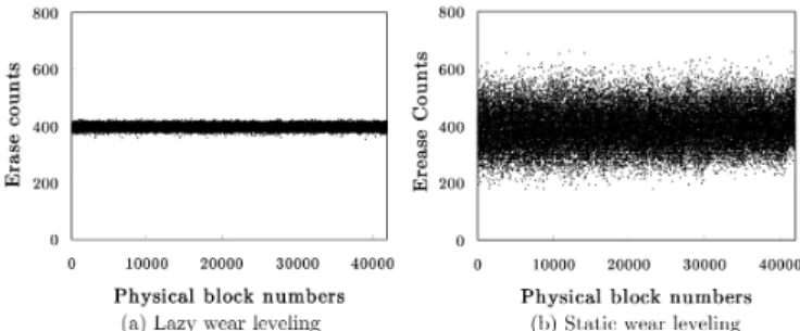
Figure 15. The final distribution of blocks’ erase counts under the notebook workload.
Figure14shows the standard deviations when using lazy wear leveling and static wear leveling under four types of disk work-loads. The X-axes and Y-axes indicate the total amount of data written into the disk and the standard deviations, respectively. Let the stable interval of a wear-leveling algorithm be the longest time period [t, t0] in which the standard deviations at time points t and
t0 are the same. A wear-leveling algorithm is stable if its stable interval increases as the total amount of data written into the disk increases. Figure14(a) shows that lazy wear leveling was stable under all workloads. On the contrary, Fig.14(b) shows that static wear leveling was instable. Figure15shows the final distribution of erase counts under the notebook workload. As static wear leveling was instable, the belt of erase counts gradually grew thicker dur-ing experiments. A closer inspection of the static wear leveldur-ing’s results revealed two causes of this instability.
Static wear leveling proactively moves static data away from physical blocks with a low erase recency (called static blocks here-after), giving static blocks a chance to participate in garbage col-lection. Erasing a static (physical) block forcibly re-maps the log-ical block previously mapped to this static block to a spare block. However, static wear leveling conducts this re-mapping regardless of whether the spare block is also static or not. Under the note-book workload, there was a 70% probability that static wear lev-eling would re-map a logical block of a low update recency from a static block to another static block. This impeded the aging of static blocks only. The second problem is that static wear leveling erases static blocks regardless of their (absolute) erase counts. Un-der the notebook workload, there was a 50% probability that the block erased by static wear leveling was an elder block. Erasing an elder block does not help wear leveling in any way.
6. An SSD Implementation
6.1 Hardware ArchitectureThis study reports the implementation of the lazy wear-leveling al-gorithm in a real solid-state disk. This implementation used Global UniChip Cooperation’s GP5086 system-on-a-chip (i.e., SoC)
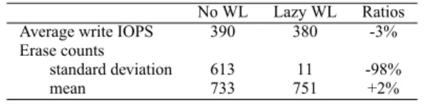
con-No WL Lazy WL Ratios Average write IOPS 390 380 -3% Erase counts
standard deviation 613 11 -98%
mean 733 751 +2%
Table 2. Evaluation results of the GP5086-based SSD prototype. The average size of write requests was 22 KB.
troller for solid-state disks. The controller includes an 150-MHz ARM7 core, a BCH-based ECC engine, SLC/MLC flash interfaces, and host interfaces including serial ATA and parallel ATA. This controller supports 128KB of embedded SRAM for run-time vari-ables and FTL mapping tvari-ables. GP5086 features a four-channel architecture aiming at high sustained data transfer rates. GP5086 erases in terms of four parallel flash blocks in the four channels, while reading and writing do not necessarily involve all the chan-nels. We designed a solid-state disk using GP5086 and four MLC flash chips, with one chip for each channel. The effective page size and block size were 4KB and 2MB, respectively. The GP5086 firmware implemented a SAST-like FTL algorithm optimized for its multichannel architecture. This firmware also included the lazy wear-leveling algorithm for performance evaluation.
6.2 Experimental Results
In this experiment, the over-provisioning ratio was 2.5%, and the threshold parameter Δ was 16. The solid-state disk was connected to a Windows-based PC. A user application ran on this PC and replayed the notebook disk workload one hundred times on the solid-state disk using non-buffered Win32 I/O APIs. To speed up the experiment, the GP5086 firmware replaced its flash-accessing routines with dummy functions.
The results in Table2show that enabling lazy wear leveling significantly reduced the standard deviation from 613 to 11, while the mean increase was only 2%. These numbers are consistent with the simulation results. We also measured the time overhead in terms of the average number of write requests completed per second (i.e., the average write IOPS). When measuring IOPS, the firmware switched back to real flash-access routines and the experiment measured the response times of one million write requests. Results show that enabling lazy wear leveling decreased the write IOPS by 3%, which is slightly greater than the 2% mean increase. This is because wear leveling involves extra copy operations in addition to erasing blocks.
7. Conclusion
Successful wear leveling relies on monitoring not only the current wear in flash, but also recent trends in flash wear. Thus, keeping track of blocks’ erase frequency (i.e., erase counts) and erase re-cency is a fundamental design issue. This study presents a simple but effective wear-leveling design called lazy wear leveling. This approach does not require any extra data structures for storing erase counts in RAM. Instead, it borrows the mapping information from the sector-translating algorithm to seek out data that has not been updated recently, and utilizes only in-flash erase counts to identify worn blocks. The timely re-mapping of these data to worn blocks helps even out flash wear.
Lazy wear leveling subjects wear evenness to a threshold vari-able. This study shows the feasibility of on-line overhead estimat-ing usestimat-ing an analytical overhead model. Based on these estima-tions, lazy wear leveling can tune the threshold variable for appro-priate balance between overhead and wear evenness. A series of trace-driven simulations show the merits of lazy wear leveling, and a prototype proves the applicability of lazy wear leveling in real solid-state disks.
References
[1]N. Agrawal, V. Prabhakaran, T. Wobber, J. D. Davis, M. Manasse, and R. Panigrahy. Design tradeoffs for SSD performance. In ATC’08:
USENIX 2008 Annual Technical Conference on Annual Technical Conference, pages 57–70. USENIX Association, 2008.
[2]L.-P. Chang and C.-D. Du. Design and implementation of an efficient wear-leveling algorithm for solid-state-disk microcontrollers. ACM
Trans. Des. Autom. Electron. Syst., 15(1):1–36, 2009.
[3]L.-P. Chang and T.-W. Kuo. Efficient management for large-scale flash-memory storage systems with resource conservation. ACM
Transactions on Storage, 1(4):381–418, 2005.
[4]L.-P. Chang, T.-W. Kuo, and S.-W. Lo. Real-time garbage collection for flash-memory storage systems of real-time embedded systems.
ACM Trans. on Embedded Computing Sys., 3(4):837–863, 2004.
[5]Y.-H. Chang, J.-W. Hsieh, and T.-W. Kuo. Improving flash wear-leveling by proactively moving static data. IEEE Transactions on
Computers, 59(1):53 –65, jan. 2010.
[6]M.-L. Chiang, P. C. H. Lee, and R. chuan Chang. Using data clustering to improve cleaning performance for flash memory. Software Practice
and Experience, 29(3):267–290, 1999.
[7]A. Gupta, Y. Kim, and B. Urgaonkar. Dftl: a flash translation layer em-ploying demand-based selective caching of page-level address map-pings. In ASPLOS ’09: Proceeding of the 14th international
confer-ence on Architectural support for programming languages and oper-ating systems, pages 229–240. ACM, 2009.
[8]IEEE Standards Association. IEEE Std 1666-2005 IEEE Standard SystemC Language Reference Manual. pages 1–423, 2006.
[9]D. Jung, Y.-H. Chae, H. Jo, J.-S. Kim, and J. Lee. A group-based wear-leveling algorithm for large-capacity flash memory storage systems. In CASES ’07: Proceedings of the 2007 international conference on
Compilers, architecture, and synthesis for embedded systems, pages
160–164. ACM, 2007.
[10]J.-U. Kang, J.-S. Kim, C. Park, H. Park, and J. Lee. A multi-channel architecture for high-performance NAND flash-based storage system.
J. Syst. Archit., 53(9):644–658, 2007.
[11]H.-J. Kim and S.-G. Lee. An effective flash memory manager for reliable flash memory space management. IEICE Transactions on
Information and System., 85(6):950–964, 2002.
[12]S.-W. Lee, D.-J. Park, T.-S. Chung, D.-H. Lee, S. Park, and H.-J. Song. A log buffer-based flash translation layer using fully-associative sector translation. Trans. on Embedded Computing Sys., 6(3):18, 2007.
[13]Wear-Leveling Techniques in NAND Flash Devices. Micron R Appli-cation Note (TN-29-42), 2008.
[14]Wear Leveling in Single Level Cell NAND Flash Memories.
Numonyx R Application Note (AN1822), 2006.
[15]C. Park, W. Cheon, J. Kang, K. Roh, W. Cho, and J.-S. Kim. A reconfigurable ftl (flash translation layer) architecture for nand flash-based applications. ACM Trans. Embed. Comput. Syst., 7(4):1–23, 2008.
[16]K. Rosen. Discrete mathematics and its applications. McGraw-Hill New York, 2003. ISBN 0072424346.
[17]K9F8G08B0M 1Gb * 8 Bit SLC NAND Flash Memory Data Sheet.
Samsung Electronics Company, 2006.
[18]K9MDG08U5M 4G * 8 Bit MLC NAND Flash Memory Data Sheet.
Samsung Electronics Company, 2008.
[19]Y. J. Seong, E. H. Nam, J. H. Yoon, H. Kim, J.-Y. Choi, S. Lee, Y. H. Bae, J. Lee, Y. Cho, and S. L. Min. Hydra: A block-mapped parallel flash memory solid-state disk architecture. IEEE Transactions
on Computers, 59:905–921, 2010.
[20]Wear Leveling. Spansion R Application Note (AN01), 2008.
[21]SmartMedia R Specification. SSFDC Forum, 1999.
[22]S. P. D.-H. L. S.-W. L. Tae-Sun Chung, Dong-Joo Park and H.-J. Song. System software for flash memory: a survey. In EUC ’06: Embedded