Tainan, Taiwan 701
Chih-Wei Chang
National Chiao Tung University
Department of Electrical and Control Engineering Hsinchu, Taiwan 300
Chen-Ming Hsu Ching-Hsing Luo
National Cheng Kung University Department of Electrical Engineering Tainan, Taiwan 701
E-mail: robinluo@mail.ucku.edu.tw
Jin-Chern Chiou
National Chiao Tung University
Department of Electrical and Control Engineering Hsinchu, Taiwan 300
共MDE兲 and a ZigBee protocol chip for physiological signal acqui-sition. To improve signal quality with low electrode–skin interface impedance, a silicon-based MDE is fabricated via micromachining tech-nology. The proposed wireless sensor can provide four different chan-nels for up to 10 kHz bandwidth, 10-bit resolution biomedical signal transmissions. Different from other systems, the proposed wireless sen-sor employs a novel power management method for physiological sig-nals to reduce power consumption. The proposed wireless sensor suc-cessfully transmits electrocardiogram 共ECG兲 signals and four-channel electroencephalogram 共EEG兲 signals with power consumptions of 92.7 and 56.8 mW respectively. It consumes 46% less power than the original sensor without power management 共173 mW兲 in ECG acquisition and 67% less power in EEG acquisition. The circuit printed-circuit-band area in the proposed wireless sensor is 3.5⫻4.5 cm, suitable for various por-table biomedical applications. © 2009 Society of Photo-Optical Instrumentation En-gineers. 关DOI: 10.1117/1.3124190兴
Subject terms: MEMS sensor; biotelemetry; signal processing; power-efficient. Paper 08139SSRR received Aug. 19, 2008; revised manuscript received Mar. 9, 2009; accepted for publication Mar. 9, 2009; published online Apr. 29, 2009.
1 Introduction
Physiological signals such as electrocardiogram 共ECG兲, electroencephalogram 共EEG兲 and electromyogram 共EMG兲 signals are extensively used and analyzed in biomedical applications.1–3 In these applications, biopotential elec-trodes transform the physiological signals from skin tissue to the processing circuit and generate electrode–skin inter-face impedance, which acts as a voltage divider with the amplifier input resistance to transport biosignals. High in-terface impedance contributes to the thermal noise and sig-nal attenuation in the system. Accordingly, the most impor-tant characteristic of a biopotential electrode is low electrode–skin interface impedance, which is to propagate signals without attenuation or the production of noise.4 Ad-ditionally, protocol-implemented systems are broadly ap-plied and more convenient and comfortable for users and patients in biomedical applications.5 The lifetime of these systems powered by batteries of limited size typically is too short for long-term applications, because the transceiver modules of these systems consume considerable power.6 The channel bandwidth of these systems significantly ex-ceeds the requirement of the physiological signal and there-fore, power is wasted.
This work presents various microelectromechanical sys-tem 共MEMS兲-based dry electrodes 共MDEs兲 and a novel power-management method associated with the ZigBee protocol for physiological signal acquisition. Silicon-based MDE fabricated via micromachining technology is pro-posed to improve signal quality with low electrode–skin
interface impedance. Low electrode–skin interface imped-ance is usually required in surface-mounted sensing, be-cause high interface impedance may be-cause serious signal attenuation while recording. In other words, the signal-to-noise ratio may be reduced. The MDE with microprobe arrays is placed on the skin, passing through the outer skin layer, stratum corneum共SC兲, into the electrically conduct-ing tissue layer, stratum germinativum 共SG兲, but not into the dermis layer, preventing pain or bleeding. Therefore, it avoids the high-impedance SC layer and provides superior signal transmission to standard wet electrodes that use elec-tric gel.7Because MDE is expected to overcome the high-impedance characteristics of the SC, neither skin prepara-tion nor applicaprepara-tions of electrolytic gel are required.
The proposed wireless sensor includes MDE and a wire-less sensing circuit, whose block diagram is displayed in Fig.1. The wireless sensing circuit comprises an instrument amplifier, a filter, an analog-to-digital converter, memory, a microprocessor, a voltage regulator for power management, and a ZigBee transceiver. The total power consumption 共173 mW兲 is measured using an Agilent U8001A dc power supply with the voltage set to 3.6 V. The average current in work mode and idle mode is carefully observed by an Agi-lent DAO5012A oscilloscope. The ZigBee transceiver 共122 mW, 71% of power consumed by the whole wireless sensor兲 consumes most of the power consumed by the wire-less sensing circuit. Hence, this work develops a novel power-management system with increased power effi-ciency, based on the characteristics of various physiological signal.8For example, the required bandwidth of the ECG is 40 kHz bps 共4 k sample rate, 10-bit resolution兲, which is 1932-5150/2009/$25.00 © 2009 SPIE
much lower than the single-channel bandwidth of the Zig-Bee standard共250 kbps兲 , so that the ECG signal could be stored six times in the memory共250 kbytes兲. Then, the six signals in the memory are sent at one time, saving 5/6 of the transceiver power because the transceiver is turned off the rest of the time. In this work, considering the ZigBee protocol data package characters and according to the Zig-Bee network specification,10 the value on ZigBee network data broadcast is 120 kbytes. So, the microcontroller with 128 kbytes of in-system, self-programmable flash program memory is selected for this system. With the high-performance MDE and novel power-management approach in the ZigBee protocol, the proposed wireless sensor can be adopted power-efficiently for physiological signal acquisi-tion.
2 Material and Methods 2.1 Hardware Overview
2.1.1 MDE
Electrode impedance is the most important issue in silicon MDE designs. To reduce the impedance of standard elec-trodes, the skin must always be prepared, involving the abrasion of SC and the use of electrolytic gel to improve electrical conductivity. The skin anatomy is a layered archi-tecture, which can be simply divided into three layers from top to bottom: SC, SG, and dermis. The SC acts as a fluid barrier and therefore exhibits electrical isolation character-istics. This layer is constantly renewing itself and consists of dead cells. The SG is the region where the cells divide themselves, grow, and are displaced. Because the SG is composed of living cells, which consist almost completely of liquid, this layer of skin is an electrical conducting tissue that is comparable to an electrolyte. The dermis, which is below the SG, contains vascular and nervous components as well as sweat glands and hair follicles; it is also electri-cally conducting. Pain originates in the dermis. However, complete removal of SC is very painful and not recom-mended; most measurements using standard electrodes in-volve slight or no abrasion, and electrolytic gel is used, diffusing into the SC to improve its conductivity.
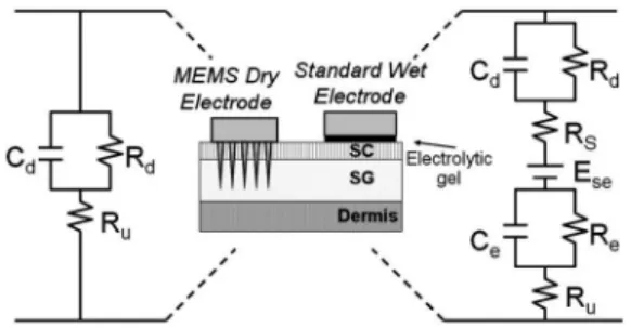
In this work, the MDE with microprobe array can pen-etrate into the SC layer and reach the SG layer to reduce the electrode–skin interface impedance. Figure 2 presents the
electrical model of both standard wet electrodes and MDEs. Comparing these two models indicates that the overall im-pedance of the spiked electrode is less than that of the standard electrode. Additionally, an electrode with a micro-probe array can be anticipated to have a lower electro-chemical noise.4
The dry electrode is fabricated using both isotropic and anisotropic reactive ion etching-inductively coupled plasma processes. The isotropic etching process produces the sharp probe tip, and anisotropic etching produces a cylindrical probe body with a height of approximately 250m. In the final stage of the process, wet-etching is utilized to release the hard mask from the probe tip. To ensure electrical con-ductivity and biomedical compatibility, the probes are coated with Ti/Pt by dc sputtering. Figure 3 depicts the fabrication process.
2.1.2 Front-end circuit
The transmitter node consists of six parts: front-end ampli-fiers, filters, flash programmable memories, a microcontrol-ler, wireless transceivers, and a power supply. An instru-mentation amplifier 共INA327, Texas Instruments Incorporated, USA兲 is used as the preamplifier for sensing the biophysiological signals in the biotelemetry system. The characteristics of INA327 are high common-mode re-jection, high performance, low cost, rail-to-rail input and output range, single-supply voltage 共+2.7– +5.5 V兲, and small size共MSOP-8兲. INA 327 can be enabled by applying logic control signal from the microcontroller. A logic low-voltage level turns off the amplifier and reduces its supply current from 2.4 mA to typically 2A. These features make it suitable for the system application.
The gain of this instrumentation amplifier can be tuned for various biophysical measurements by trimming the re-sistor value, and the bandwidth of the filters can be de-signed to suit the system.
Fig. 1 Block diagram of proposed wireless sensor.
Fig. 2 Electrode–skin interface comparison between spiked dry and
electrode standard wet electrode.
full. MCU links to the radio frequency共rf兲 transceiver mod-ule and provides communicating data. In this system, the microcontroller performs the functions of power-management control, enabling the front-end amplifier cir-cuits and filters, switching the sensing channels, processing the signals, and storing data in the memory.
2.1.4 Wireless transceiver
The wireless module is IEEE 802.15.4/ZigBee-compliant. It contains a powerful 8-bit 8051 microprocessor and an rf single-chip 共CC2420, from Texas Instruments Incorpo-rated兲 2.4 GHz IEEE 802.15.4-compliant rf transceiver. The rf transceiver module is employed as a communication transceiver in bidirectional telemetric devices. A wireless sensor network can be built from the transceiver modules for various applications. The transmission range of the transceiver is 100 m共LOS兲.
2.1.5 Power supply
The power-supply device consists of a +3.3 V voltage regulator integrated circuit 共IC兲, RT9167-33, and bulk de-coupling capacitors. The RT9167 IC is a low-dropout-voltage and low-noise regulator and therefore, it is suitable for portable applications. The shutdown mode of nearly zero operation current makes the IC appropriate for use in battery-powered devices. A rechargeable 3.6 V Li-polymer battery pack共700 mA/h兲 provided the power to the unit. 2.1.6 Connection to PC
In the receiving node, the device can be connected to a PC via a universal serial bus共USB兲 port or a universal asyn-chronous receiver/transmitter共UART兲 port. The logic level converter共MAX232, from Maxim兲 is used to convert the transistor–transistor logic-level voltages to⫾12 V levels to implement the RS-232 serial protocol that governs commu-nication with the PC. The custom-developed software, writ-ten in Basic and Lab-View, allows the PC to record, plot, and use the received data.
2.2 Novel Power-Management Method
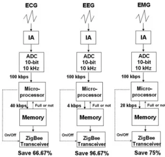
Different physiological signals have different characteris-tics, which require different things of the implemented sys-tem. ECG requires 10-bit resolution and a 4 kHz sample rate, EEG requires 10-bit resolution and a 400 Hz sample rate, and EMG requires 7-bit resolution and a 4 kHz sample rate. In the proposed system, the fixed-specification ADC 共10-bit, 10 kHz sample rate兲 is applied to acquire various physiological signals, which are then processed to meet the requirements described above. The bandwidth is reduced and stored in the memory until it is full. Before the memory is full, the ZigBee transceiver is in standby mode and will be turned on by the microprocessor when the memory is full. Theoretically, the ZigBee transceiver saves
66.67, 96.67, and 75% of the power in ECG, EEG, EMG applications. Figure 4 presents the flow chart of the pro-posed power-management method.
2.3 Firmware Overview
The firmware that drives the microcontroller is developed in assembly language. Figure5shows the flow charts of the main program, the system signal process, and power con-trol. The program, which runs on the microcontroller, com-prises a main routine that is divided into three portions of code. The first part initializes the system circuits 共commu-nications module, ADC, timer兲 and sets the parameters of the system signal processing. The second part is the signal-processing function and the program loop that performs the ADC conversions, stores digital data in memory, and sends data through the rf transceiver module. The third part per-forms the power-management function. The microcontrol-ler is programmed to enable/disable the front-end signal processing circuits, choose different numbers of sensor
Fig. 5 Flow diagram of the firmware code. Fig. 4 Flow chart of power management.
channels according to user requirements, and switch be-tween the system’s work/idle modes to reduce power con-sumptions.
The main state involves a program loop in which the system switches to the idle mode and periodically wakes up, acquires sensor data, and stores them in memory. As soon as the buffer memory is full, the system sends all of the data simultaneously through the rf transceiver device and starts to wait for new data. In the receiving node, the system can be connected to a PC through an RS-232 port or a USB port. Stored data in the internal electrically erasable programmable read-only memory are sent to the PC to be processed thoroughly using the graphical interface soft-ware.
The data broadcast of the ZigBee transceiver is 120 kHz bps, which exceeds most biomedical requirements, and can be set more efficiently with the proposed technique. Figure 4 displays the flow chart of the proposed power-management method. Different physiological signals have different characteristics and different requirements of the system. ECG requires 10-bit resolution and a 4 kHz sample rate, EEG needs 10-bit resolution and a 400 Hz sample rate, and EMG requires 7-bit resolution and a 4 kHz sample. In the proposed system, the fixed-specification ADC共10-bit, 10 kHz sample rate兲 is used to acquire differ-ent physiological signals, and these acquired signals are processed to meet their requirements. The bandwidth is re-duced and stored in memory until the memory is full. Be-fore the memory becomes full, the ZigBee transceiver is in idle mode and turned on by the microprocessor. Theoreti-cally, the ZigBee transceiver consumes 66.67, 96.67, and 75% less power in the ECG, EEG, and EMG applications.
3 Experimental Details
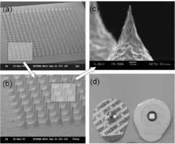
Figures 6共a兲–6共c兲show the scanning electron microscopy 共SEM兲 of the fabricated MDE. Figure 6共d兲 presents the packaged MDE. The diced dry electrodes were packaged on a flexible printed circuit board 共PCB兲 for convenient
usage. After the fabricated MDE was packaged, steriliza-tion was performed with a 25 Kgy gamma-ray from Cobalt 60 共China BioTech Corp., Taiwan兲. Figure 6 depicts the SEM of the MEMS sensor. The etched dry electrode con-sists of a 20⫻20 microprobe array; the etch probe is ap-proximately 250m high and 35 m in diameter. A block bulge is observed around 50m at the base of the probe, caused by the isotropic etching shape in the second fabri-cation process. Accordingly, the effective penetration length of the probe is about 200m. The characterization of the electrode–skin interface impedance is of utmost im-portance in impedance-based biosensing.10 To verify the performance of electrode–skin interface impedance, elec-trode impedance spectroscopy is adopted to evaluate the fabricated MDE. The experiment is held by two MDEs
at-Fig. 7 Measurement results of the proposed MDE.
Fig. 8 Comparison of EEG and ECG signals measured by
pro-posed MDE and standard wet electrode.
tached to the skin at a distance of 4 cm from each other, and an electrode–skin–electrode impedance architecture is thus constructed. The test signal is applied to the first MDE, flowed through the skin tissue, and finally passes the sec-ond MDE. Therefore, the test results can be regarded as a summary of the impedance of a two-electrode–skin inter-face.
The measurements plotted in Fig.7, without skin prepa-ration, demonstrate that the MDE is superior to standard wet electrode in reducing the electrode–skin interface im-pedance. Nineteen test series of samples are adopted care-fully in the impedance experiment, involving five subjects and three electrodes 共wet electrode with skin preparation, wet electrode without skin preparation, and dry electrode without skin preparation兲. Figure7 plots the measured re-sults. In the frequency range of interest for EEG and ECG 共0.5–100 Hz兲, the impedance of MDE is at least 13 times lower than that of the standard wet electrode.
Moreover, to validate the practical recording perfor-mance of the proposed MDE, EEG and ECG simulta-neously recorded by the proposed MDE and standard wet electrode are shown in Fig.8. The solid line and the dotted line represent the measurements of the ECG and EEG sig-nals by the proposed MDE and the standard wet electrode,
respectively. The ECG signal is an Einthoven triangle, pro-duced by an ECG amplifier with a right-leg and shield drive circuit.9The signals are all sensed by MDE and processed by the front-end circuit. All of the signals are acquired by a 10-bit resolution analog-to-digital converter with a 4 kHz sample rate; four EEG signals used independent channels for wireless transmission. From Fig.8, the comparison re-sult indicates that the recordings of the MDE are the same as those made using the standard wet electrode. Because wet electrodes are commonly used in modern medical ap-plications, these results demonstrate that the proposed MDE meets modern medical monitoring requirements. 4 Results and Discussion
Figure 9 shows the whole wireless sensor. To verify the effectiveness of the system, ECG and four-channel EEG signals are input to measure the performance of the system. Figure 10 plots the received EEG signals processed with the proposed power-management method. Figure8displays the received single ECG signal lead II; the significant fea-tures of the waveform are the P, Q, R, S, and T waves, the
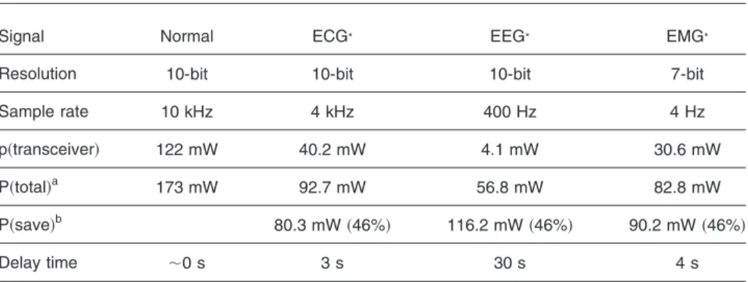
Table 1 Power comparison table in different applications.
Signal Normal ECG* EEG* EMG*
Resolution 10-bit 10-bit 10-bit 7-bit
Sample rate 10 kHz 4 kHz 400 Hz 4 Hz
p共transceiver兲 122 mW 40.2 mW 4.1 mW 30.6 mW
P共total兲a 173 mW 92.7 mW 56.8 mW 82.8 mW
P共save兲b 80.3 mW共46%兲 116.2 mW共46%兲 90.2 mW共46%兲
Delay time ⬃0 s 3 s 30 s 4 s
aP共total兲: the power consumptions consist of front-end amplifiers, filters, flash programmable
memo-ries, microcontrollers, and wireless transceivers.
bP共save兲: the saving power value in different biomedical applications. Fig. 9 Picture of the proposed wireless sensor.
Fig. 10 Four EEG signals sensed and transmitted by proposed
duration of each wave, and particular time intervals, such as the P-R, S-T, and Q-T intervals.11The P, Q, R, S, and T functions can be used for ECG monitoring applications. From Figs. 8 and10, the ECG and EEG are successfully transmitted and the power consumption of the whole sens-ing node is 92.7 mW 共ECG兲 or 56.8 mW 共EEG兲, 46% 共ECG兲 and 67% 共EEG兲 less than the power consumed 共173 mW兲 by the original system. Table 1 compares the power consumed by the proposed system in various appli-cations.
Figure9 presents the proposed wireless sensor, includ-ing MDE, front-end circuit, microprocessor, and ZigBee module. Three circuit PCBs are stacked, and the connection lines are hidden between the PCBs. The area of the circuit PCB is 3.5⫻4.5 cm, and the circuit is powered by a 3.6 V Li-ion battery. Although the proposed system sufficiently reduces the power consumed by the protocol-implemented biotelemetric system, it also increases the delay between the sensors and the receiving station. This delay can be adjusted by varying the memory and the data compression ratio. The power is theoretically reduced, but the delay al-lowed by the application must also be considered. How-ever, in the on-site monitoring and recording, any time de-lay is not suggested; the portability used for homecare or off-site recording is usually not concerned with the delay. The equipment needing the power-saving methodology should mention the delay and limit the application in home-care or off-site recording.
5 Conclusion
The proposed wireless sensor, including MDE and a novel power-management method, was successively used to ac-quire physiological signals. Use of this system improves comforts of wearing sensors and increases device lifetime substantially. These results can be the starting point for the development of a novel and miniaturized biomedical sens-ing device that can be either worn or implanted by the patients and lead to more individualized health care ser-vices.
Acknowledgment
The authors thank the National Science Council of the Re-public of China, Taiwan, for financially supporting this re-search under Contract No. NSC 95-2218-E-009-017.
References
1. A. Alesanco, S. Olmos, J. Salcedo, R. Istepanian, and J. Garcia, “A real-time multilead ECG compression and de-noising method for a mobile telecardiology system,” Int. Congr. Comput. Bioeng. 1, 237– 242共2003兲.
2. C. J. James and C. W. Hesse, “Independent component analysis for biomedical signals,”Physiol. Meas27, R15–R39共2005兲.
3. C. J. James and O. J. Gibson, “Temporally constrained ICA: An ap-plication to artifact rejection in electromagnetic brain signal analy-sis,”IEEE Trans. Biomed. Eng.50共9兲, 1108–1116 共2003兲.
4. H. A. Miller and D. C. Harrison, Biomedical Electrode Technology, Academic Press, New York共1974兲.
5. R. S. H. Istepanian and A. A. Petrosian, “Optimal zonal wavelet-based ECG data compression for a mobile telecardiology system,” IEEE Trans. Inf. Technol. Biomed.4共3兲, 200–211 共2000兲.
6. C.-M. Hsu, W.-T. Liao, C.-H. Luo, and T.-C. Chou, “The 2.4 GHz biotelemetry chip for healthcare monitoring system,”Sens. Actuators, A139共1–2兲, 245–252 共2007兲.
7. P. Griss, P. Enoksson, H. K. Tolvanen-Laakso, P. Meriläinen, S. Oll-mar, and G. Stemme, “Micromachined electrodes for biopotential measurements,”J. Microelectromech. Syst.10共1兲, 10–16 共2001兲.
8. C. L. Chang, S.-C. Lai, C. M. Hsu, C. W. Chang, C. H. Luo, and J. C. Chiou, “A power-efficient wireless biotelemetry for MEMS sensing physiological signal analysis,” Presented at Asia-Pacific Conf. on
Transducers and Micro-Nano Technology, Tainan, Taiwan, June
22–25, 2008.
9. P. Griss, P. Enoksson, and G. Stemme, “Micromachined barbed spikes for mechanical chip attachment,” Sens. Actuators, A95共2兲,
94–99共6兲 共2002兲.
10. J. C. Chiou, L.-W. Ko, C.-T. Lin, C.-T. Hong, and T-P. Jung, “Using Novel MEMS EEG Sensors in Detecting Drowsiness Application,” in
IEEE Biomedical Circuits and Systems Conference, IEEE, pp. 33–36
共2006兲.
11. J. J. Carr and J. M. Brown, Introduction to Biomedical Equipment
Technology, 4th ed., Prentice Hall, New York共2001兲.
Chia-Lin Chang received his BS in
electri-cal engineering from National Kaohsiung University of Applied Sciences, Kaohsiung, Taiwan in 2005 and an MS in electrical en-gineering from National Cheng Kung Uni-versity, Tainan, Taiwan in 2007. He is now pursuing a PhD at National Cheng Kung University. His research field includes biote-lemetry device and chip design, biomedical wireless communication, and analog IC design.
Chih-Wei Chang received BS and MS
de-grees in electrical and control engineering from National Chiao-Tung University, Tai-wan in 2003 and 2005, respectively. He is currently working toward a PhD, and his re-search interests are in the areas of MEMS, bioelectronics, brain–machine interface, and biomedical engineering.
Chen-Ming Hsu received BS, MS, and PhD
degrees in electrical engineering from Na-tional Cheng Kung University, Tainan, Tai-wan in 2001, 2003, and 2007, respectively. He is now the engineer of Lite-Med, Inc., Taiwan. His research field includes rf rf IC, biomedical signal processing circuit, medi-cal instrument design, and biotelemetry chip design.
Ching-Hsing Luo received his BS in
elec-trophysics at National Chao Tung Univer-sity, Taiwan in 1980 and his MS in biomedi-cal engineering at Johns Hopkins University, USA in 1987, and he received his PhD in biomedical engineering at Case Western Reserve University, USA in 1991. He is currently a professor at National Cheng Kung University, Tainan and Director of the Wireless Mixed Biochip Laboratories of the same university. His main research interests are biomedical instrumentation, instrumentation system design, althletic training instrumentation, scientific aided device implementation for the disabled, and biomedical GPS wireless-communication monitoring navigation system and biotelemetry
Electrical and Control Engineering, National Chiao-Tung University共NCTU兲, Taiwan, in 1992, he was with the Center for Space Structure and Control, University of Colo-rado, as a Research Associate 共1991– 1992兲. His research interests include MEMS, biomedical chips, gas sensors, and modeling and control