The Design and Implementation of the GPS Anchor Node for
Wireless Sensor Network
Y.-C. Kan
1, a, H.-C. Lin
2,band Y.-M. Hong
3,c1 Department of Communications Engineering, Yuan Ze University
No. 135 Yuan-Tung Road, Chung-Li, Taoyuan 32003, Taiwan
2
Department of Health Risk Management, China Medical University No. 91 Hsueh-Shi Road, Taichung 40402, Taiwan
3Department of Design for Sustainable Environment, MingDao University
No. 369 Wen-Hua Road, Peetow, Changhua 52345, Taiwan
a [email protected], b [email protected], c [email protected]
Keywords: Anchor node, GPS, WSN, Localization, Trigger, Accelerometer.
Abstract. For wireless sensor network localization, the anchor nodes provide the reference location to other nodes and, hence, are a key component in the location-aware applications. In this study, the fixed or mobile anchor node with GPS location aware are proposed and implemented. The effects of environment on the location information of the anchor nodes are first measured and the variation of the measured data varies in the range of 50 mini-arcseconds. The anchor nodes are battery-powered and the fixed one is equipped an extra solar charging device. The power scheme combines the periodic wakeup with the moving detection using the Bayes decision rule. The power consumptions for each component are analyzed and the total power consumption is then formulated. By adjusting the wakeup period, the proposed GPS anchor node can be applied to many outdoor applications that require long last power with little maintenance.
Introduction
Location-aware has become the key component in almost all the wireless applications. Most location techniques in wireless sensor network (WSN) employ both the range-based and range-free schemes. The relative distances between nodes in the range-based schemes can be obtained using time of arrival (TOA), time difference of arrival (TDOA), angle of arrival (AOA), and the received signal strength indicator (RSSI) technologies [1,2]. The choice of the rang-based scheme partially depends on the hardware implementation. For example, the directional antenna or antenna array is recommended in implementing the sensor node if the AOA scheme is used [1]. On the other hand, the TOA or TDOA scheme may require hardware with the nano-second resolution, which is much impractical for current WSN node implementation [3]. Therefore, the most feasible way to the range-based localization is the utilization of RSSI, which is built-in feature of the RF chip in WSN mote. For the range-free scheme, various location schemes are derived based on the triangulation method with reference or anchor point [4]. No matter if the anchor point is fixed or mobile, the location of the anchor point is the most important factor for these schemes. For WSN outdoor applications, the GPS is the most popular choice for location information. To provide the RSSI-based distance estimation and reference location, the GPS is integrated with the WSN mote in this paper. The hardware and software design are described in next section prior to the section of results and discussions. Finally the conclusions are then addressed.
GPS Anchor Node Design
Hardware Design. The proposed GPS anchor node consists of the Tmote Mini Plus [5], a GPS chip, power components and antennas. The Tmote Mini Plus includes the TI MSP430
microcontroller, CC2420 RF transceiver, an amplifier, and a 1024KB flash memory. The ET-318 GPS chip from
(a)
(b)
Fig. 1 The function diagram of the fixed GPS anchor node Fig. 2 The pictures of the proposed GPS anchor node
GlobalSat [6] is employed in the node. For power management, a linear regulator, a low voltage current limit switch, and a 3-axis accelerometer are used. The switch controls the on/off status of the GPS chip and the accelerometer is designed to be a trigger component which wakes up the RF transceiver and GPS chip. The fixed GPS anchor node is supplied by two 2600 mAh Li-ion batteries which are in parallel and charged by a solar cellular board. Another lithium (Li) battery is installed to provide the powers to real-time counter (RTC) and SRAM in the GPS chip. The latest ephemeris is kept in the SRAM and the RTC can calculate the current ephemeris based on the stored ephemeris and the time passed. Two antennas are used in this node: one is an active GPS antenna for 1.5754GHz and the other is a quart-wavelength monopole antenna for 2.4GHz. The function block of the proposed GPS anchor node is shown in Fig. 1. Fig. 2 (a) shows the pictures of the mobile anchor nodes. The fixed GPS node with antennas, battery, and enclosure is shown in Fig. 2 (b).
Software Consideration. The proposed GPS anchor node is supported by the TinyOS [7] and all the software are developed by using the nesC. In addition to the MAC and network functions which are supported by the TinyOS, several application requirements are considered. These include the environment effects on the received GPS data, the power consumption, and the wakeup threshold.
The GPS chip supports the NEMA protocol and returns the received data from a RS232 connection to the MCU. Among the NEMA data sets, the global positioning system fix data (GGA) is used. One example of the received string is following:
$GPGGA,021702.481,2458.0787,N,12116.0492,E. (1) The dollar sign denotes the beginning of the data set and $GPGGA is the message ID for GGA. The
second column is the UTC time with the format hhmmss.sss, where h denotes hour, m denotes minute, and s denotes second. The third one is the latitude and the fifth one is the longitude. The first two digits of the latitude are number in degree and the rest of the number is in arc-minute. Similarly, the first three digits of the longitude are number in degree and the rest of the number is in arc-minute, too. The GPS anchor node is intended to provide the accurate reference location, which is usually an absolution position in longitude and latitude. However, the slight environment changes do affect the received position data. Therefore, the GPS position data at the installation sites should be measured
as the initial template distribution and for future range-error calculation. The measured position data for different scenarios are discussed in the next section.
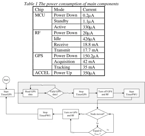
As listed on Table 1, the current consumptions of the GPS are the highest one and those of the RF chip are secondary. To reduce the power consumption of the GPS anchor node, the period of the periodic wakeup is chosen as long as possible. In addition, the moved wakeup is implemented by utilizing the data from a low power consumption 3-axis accelerometer. As shown in Fig. 3, the anchor node wakeups at a periodic time, performs the GPS data query, sends back GPS data and other data through the RF connection, and then goes back to sleep. As long as there is a node-moving status detected by the node, the node is wakeup and then performs the GPS location task. For evaluating the
Table 1 The power consumption of main components
Chip Mode Current Power Down 0.2μA Standby 1.1μA MCU
Active 330μA Power Down 20μA Idle 426μA
Receive 18.8 mA RF
Transmit 17.7 mA Power Down 150.2μA Acquisition 42 mA GPS
Tracking 35 mA ACCEL Power Up 350μA
Figure 3 The operation of the GPS anchor node
threshold of the accelerometer trigger, the measured accelerations are assumed to be the Gaussian distribution with mean, μ, and standard variation, σ. For n observationsX =
(
X1,X2,LXn)
, twosimple hypotheses H1:P=N(μ1,σ)and H2:P=N(μ2,σ) with the same standard variation and weight are assumed. The Bayes decision rule [8] is then
⎪ ⎪ ⎩ ⎪⎪ ⎨ ⎧ + > + ≤ =
∑
∑
= = n i i n i i n X H n X H 1 2 1 2 1 2 1 1 2 ) ( : 2 ) ( : μ μ μ μ δ (3)where the H1 is the hypothesis of that the node is stationary, H2 is the hypothesis of that the node is
moved. In the practical applications, the node could be moved and then stop again; hence, the stationary mean, μ , keeps change and then should be obtained from the actual measurements. The 1
2
μ is assumed to be μ1+Δ , where Δ is a parameter determined and optimized by the prior measurements. The (3) can be further derived as
⎩ ⎨ ⎧ Δ > − Δ ≤ − = 1 2 1 1 ~ : ~ : μ μ μ μ δ H H (4) where μ~ is the mean of the n measured data and Δ=Δ/2. In the implementation, the μ is the mean 1
for previous bin which has 32 16-bit values, and μ~ is the mean for current bin. The measured data and false alarm rate is presented in the next section.
Results and Discussions
The location information by the proposed anchor node is firstly measured under different scenarios. Then the false alarm rates of the designed detection scheme are also presented in this section. As shown in Fig. 4, the received longitude and latitude data are affected by the environments. The unit of the horizontal axis in these two figures is mini-arcsecond (mas), which is 1/6000 of one arc-minute. The effect of the tree on the measured latitudes and longitudes is in the range of 50 mas. Also, the measured latitude inside the building is distributed from 500 mas to 900 mas. The measured data under the open space without any shielding are in the range of 5 mas. Hence, the initial distributions of the received GPS data should be recorded right after the installation of the anchor node. As long as the GPS is motionless, the mean values of the distributions are almost unchanged. Hence, if the GPS anchor node is not moved and the variation of the received data is broadening, then the environment is somehow changed.
For moving detection, the root mean square error (RMSE) of measured acceleration data in an open space is a slightly higher than others, but the Gaussian function is still a good choice for this fitting because of its simplicity. Differences of the measured mean values for a variety of scenarios along the z-direction are within 0.01g. This implies that the variations of the measured data are almost the same as long as the position of the GPS node is stationary. According to the measured data, the false alarm rates of the moving detection are measured while the node is keep moving. As shown in the Fig. 5, the upper, middle, and bottom figures are the decision results while the z-axis acceleration direction is perpendicular (1800 against gv ), parallel, and perpendicular (900 against gv ) to the moving direction, respectively. The false alarm rate increases as the Δ increases and that of the middle one is apparently higher than others. The false alarm rate of a stationary anchor node becomes large atΔ<6. Hence, the best threshold of the moving detection for our proposed anchor node isΔ =7.
(a) (b) Fig. 4 The measured locations of the anchor node in mas under different environmental cases. (a) All the
latitudes of the measured sites are 24 degree and 58 arc-minute. (b)All the longitudes of the measured sites are 121degree and 16 arc-minute.
(a) (b) Fig. 5 The false alarm rates of the moving detection while the node is keep moving. Digit 0 and 1 stand for
stationary and moving node. Δ=7(b) Δ=14 Conclusions
An anchor node with GPS position aware is designed and implemented in this study. The power of the anchor node is supplied by two 2600 mAh Li-ion batteries charged by the solar energy. A rough test shows that the GPS anchor node can last almost 72 hours if the MCU reads the GPS data and sends data back through RF every 10 seconds. Hence, this GPS anchor node is suitable for outdoor wireless sensor network applications with little maintenance. As a side result, the received GPS data can be applied to detect the environment changes because those changes broaden the variation of the received data. The moving detection scheme provided utilizing the on board accelerometer is also measured, and the optimal threshold is then determined. More power schemes, including other moving detection rules, for the proposed GPS anchor node can be designed according to the application requirements. Hence, a flexible anchor node accommodated to different practical wireless sensor network applications is provided.
Acknowledgement
This research is supported by the National Science Council in Taiwan under Grant NSC97-2625-M-155-001 and NSC99-2625-M-451-001.
References
[1] G. Mao, B. Fidan, and B. D. O. Anderson: Wireless sensor network localization techniques. Computer Networks Vol.51 (2007), pp. 2529-2553.
[2] N. Patwari, A. O. Hero III, M. Perkins, N. S. Correal and R. J. O’Dea: Relative Location Estimation in Wireless Sensor Networks. IEEE Trans. on Signal Processing Vol. 51, no. 8 (2003), pp. 2137-2148.
[3] R. Fleming and C. Kushner: Low-power, miniature, distributed position location and communication devices using ultra-wideband, nonsinusoidal communication technology. Aetherwire Inc., Semi-Annual Technical Report, ARPA Contract J-FBI-94-058, Tech. Rep., (1995).
[4] K.-F. Ssu, C-H Ou, and H. C. Jiau: Localization with mobile anchor points in wireless sensor networks. IEEE Trans. on Vehicular Technology Vol.54, no. 3 (2005), pp. 1187-1197.
[5] Bandwave Tech. Inc., “The Tmote Mini,” [Available Online]: http://www.bandwavetech.com/en/product_2.htm.
[6] GolbalStat Inc., “ET-318 Manual,” [Available Online]: http://www.globalsat.com.tw/mana_php/support/file/ET-318-user-manual-V2.0.pdf.
[7] UC Berkley, “TinyOS Community Forum,“ [Available Online]: http://www.tinyos.net/.
[8] H. V. Poor: An Introduction to Signal Detection and Estimation, 2nd Edition, Edited by Princeton, New Jersey, Springer-Verlag, (1994).
![Fig. 1 The function diagram of the fixed GPS anchor node Fig. 2 The pictures of the proposed GPS anchor node GlobalSat [6] is employed in the node](https://thumb-ap.123doks.com/thumbv2/9libinfo/8945044.272107/2.892.91.797.149.535/function-diagram-anchor-pictures-proposed-anchor-globalsat-employed.webp)