Using Computer-Assisted Instruction for the Visualization of Proof Tree to Improve the Reading Comprehension of Geometry Proofs
6
0
0
全文
(2) textbook, a geometry proof is often presented with a single figure. When they read the proof line by line, they might fail to identify which part of the figure each proof step refers to. Fifth, students often rely on superficial visual features, such as the guess that two angles look the same in a diagram, even if they cannot be shown to be so by reasoning logically from theorems and definitions. Such heuristics are often successful, but are likely to fail in more complex problems [1]. In a geometry proof, students will regard measurement and their guesses as justifications for establishing a condition. When a figure is not drawn precisely, students will be misled by the incorrect figure and make incorrect inferences. Students encounter several common difficulties when learning geometry proofs. Regarding the above difficulties students confronted in learning geometry proof, a variety of proposals have been suggested by researchers. Some researchers have developed interactive learning environments for learning geometry, with results that are widely recognized. Examples include Geometer’s Sketchpad [16], Cabri Geometry [20], Geometry Expert [10], Cinderella [28], Géométrix [11], Geometry Explorer [15]. These systems do bring new methods for teaching and learning geometry theorem proving when compared to traditional geometry education [8,12]. Logically speaking, a geometry proof is a tree structure. In order to help students in reading proofs, we emphasize the visualization of the steps of a proof and the strategy of teaching students to understand a proof as a tree structure. Take math problem solving for example, many researchers have placed an increased emphasis on the use of visual reasoning in mathematics [2,9,21,31]. Diagrammatic teaching plays a key role in a novice’s learning of geometry proofs and helps the learner understand the meanings of theorems and diagrams. The main purpose of this paper is to propose a computer-assisted environment to help a learner understand proof. This should help the learner to understand the proof as a tree structure rather than a linear structure presented in textbook. In the following section, we first point out the steps of understanding a proof. The third section explains how an interactive proof tree and the textbook help students understand the theorem proving process. The fourth section discusses the architecture and functions of the system. The conclusion of this research and future work are presented in the last section.. 2: Reading Comprehension of Geometry Proofs We use the Yang [32] to explain the cognitive process of reading a geometry proof. The process involves superficial comprehension, referring, association, and transformation. First of all, a reader uses her prior knowledge to understand the mathematical language in the proof (superficial. comprehension). She also needs to differentiate the given conditions from the goal to be proved by referring to the given figure or create her own figure (referring). The reader can also relate the mathematical language of the problem to relevant knowledge (association). If she can recognize a theorem used in the proof by identifying the premises and conclusion of the theorem (transformation), she has a better chance of understanding the problem fully. In short, reading and understanding a geometry proof is an activity that requires various skills in multiple steps. However, most textbooks do not satisfy learners’ needs in their reading process. Effective reading is important for studying geometry. This research aims to focus on a specific issue of geometry theorem proving—reading and understanding geometry proofs. Many studies on reading comprehension focus on language learning but few deals with reading proofs. Yang [32] pointed out that there had not been complete and in-depth studies on reading and understanding geometry proofs, which remains an open research topic.. 3: Proof Organized As a Tree Structure 3.1 Solution Tree to Math Problem Solving For a long time researchers have been studying computer-assisted math learning environments which can provide diagram to help students solve math problems. Reusser [27] proposed a system called HERON that uses schema representation to develop plans and produce a solution tree. Students, from grades 3 through 9, can understand many mathematical problems through various schemata, and then describe the solution steps in detail by constructing a solution tree. It can detect mistakes in a student’s solution tree. A similar system MathCAL [3], sought to increase the detection accuracy of students’ mistakes. In the stage of “plan making”, which is one of Polya’s four problem-solving stages [26], the representation of schemata and solution tree can help students solve a problem systematically by following the steps of a plan. The system was empirically demonstrated to be effective in improving the performance of low-achievement students. In short, the solution tree can help students understand and solve complicated mathematical problems. ANGLE [18] includes a graphical editor for entering geometry “flow proofs”, a cognitive model or “expert component” for checking student proofs, and a tutor for providing feedback and advice on student’s work. A proof is represented as a graph that shows how the problem goal is supported by a chain of inferences from the given conditions. In Advanced Geometry Tutor (AGT) [22], a solution graph is also used to represent a proof. AGT employs an efficient and semi-complete procedure for constructing proofs. Either of two problem-solving strategies can be used, namely forward chaining and backward chaining. Both ANGLE and AGT focus on learner’s construction of proofs, while. - 1432 -.
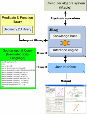
(3) our system focuses on learner’s understanding of proofs constructed by the system.. 3.2 Representing a Geometry Proof as a Tree A proof tree (Figure 1(c)) is the result of the theorem proving process. The root node of the tree is the goal condition to be proved. The tree consists of leaf nodes (for example, two segments of the same length, two angles of the same measure) and derived nodes. A new node is derived from children nodes based on some theorem (for example, two triangles are congruent due to the facts that their corresponding sides are equal in length, according to the SSS theorem). Each node of a proof tree represents a proof step. Each leaf node is a given fact or self-evident condition, e.g., a segment’s length equals that of itself. A proof tree (Figure 1(c)) is the logical structure underlying a common textbook proof (Figure 1(a) and 1(b)). In the proof tree, the logical relation between the given facts and inferred propositions are made explicit and easier to understand. This structure helps students understand the flexibility of ordering the proof steps in a common textbook proof. In a purely bottom-up presentation of the proof tree, the proof tree shows clearly that a proof must be built on the given conditions of the problem. The ultimate goal is to infer the proposition of the root node. All other inferred propositions are needed in order to lead to the root conclusion. In the proof tree, the children nodes provide sufficient conditions for establishing their parent node. By studying the proof tree, students can observe and understand the global structure of a proof.. Fig. 1 Linear proof and Proof tree Proof tree shows all steps of how to derive the goal. Figure 1(b) is a linear sequence, which is a typical textbook proof in middle school, of presenting the proof tree in Figure 1(c). In fact, a proof tree may be presented linearly with different orderings of the nodes.. A proof tree can be considered as a partial ordering relation between the nodes. A linear presentation of the tree’s nodes can be considered a scheduling task. In Figure 1(b) Proposition 2 has a higher priority than Proposition 4, which means that Proposition 2 must be presented prior to Proposition 4. The Proposition 1, Proposition 5 and Proposition 4 support Proposition 6, which means that Proposition 1, Proposition 5 and Proposition 4 should be presented before Proposition 6. A proof tree expresses clearly the logical relation between each parent node and its children nodes. If the student studies these relations carefully, she should be able to understand the proof fully.. 4: Overview of the System Architecture and Design 4.1 System Architecture We have developed a system that does automated theorem proving and visualize the steps of a proof, aiming to facilitate students’ reading and comprehension of geometry proofs. In this section, the architecture and the design principles of our system are discussed. The system components includes an inference engine, knowledge base of inference rules, and a Prolog geometry prover, a geometry visualizer driven by Geometry Script Language (GSL) which describes the conditions of a geometric figure, GeoProver [14], and proof tree visualizer. The system provides the basic features for visualizing dynamic geometry and proving theorems mechanically with rule-based and algebraic approaches. Algebraic computations are done with Maple, which talks with a Java application. The system architecture is shown in Figure 2. Maple is a popular, commercial computer algebra system (http://www.maplesoft.com/). Maple can obtain exact analytical solutions to many mathematical problems, including integrals, systems of multivariate equations, differential equations, and problems in linear algebra. Prolog is a programming language based on a small set of mechanisms, including pattern matching, tree-based data structure and automatic backtracking. We can write short Prolog programs to reason about the spatial relationships between geometric objects and check their consistency with respect to general rules. These features make Prolog a powerful language for artificial intelligence and non-numerical programming in general. We use JLog to be the Prolog kernel of our system. JLog (http://jlogic.sourceforge.net), written in pure Java, is developed by Glendon Holst as an open source project. Its primary advantage is that it can be run on almost any platform supporting Java (with or without a web browser), and as such it is well suited for educational purposes. We reconstruct a new user interface for our purpose and build more predicates with JLog. Our system does algebraic operations in Maple,. - 1433 -.
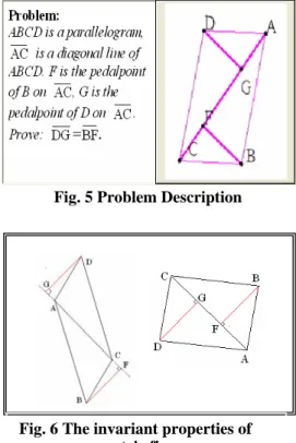
(4) then returns the result to Java, and finally shows the result in a Prolog session.. With a rule-based approach, propositions can be inferred in two directions: data-driven forward chaining and goal-driven backward chaining. The system uses logic programming to implement backward chaining, with depth-first search and backtracking. After receiving a goal proposition, the system carries out a goal-driven search in the knowledge base. If the goal proposition matches a given condition then the goal is proved. Otherwise, if a rule whose condition matches the goal is found, the system will try to prove each premises of the rule recursively. If the goal is proved, all proof steps in the inferencing process will be collected and returned as a proof tree. The learner can choose any node in the proof tree to visualize while hiding other parts in the figure. The system will draw the geometric figure with solid lines representing the condition of the parent node and dash lines representing those of children nodes in the figure. The lines are colored to distinguish the parent and children nodes.. 4.3 An Example Problem: ABCD is a parallelogram, AC is a diagonal line within ABCD. F is the pedalpoint of B on AC , G is the pedalpoint of D on (Figure 3). Prove: DG = BF .. Fig. 2 System architecture The GeoProver package is originally designed to prove geometry theorems with an algebraic approach. The system employs GeoProver to compute the coordinates of all points derived from “free” points or other derived points. It contains many generic proof schemes of geometry theorems, mainly from Chou's book and dissertation [6,7]. GeoProver can translate all geometric statements into algebraic formulas and try to solve the corresponding algebraic problem by algebraic methods. Instead of using GeoProver to prove theorems, our system uses a rule-based method, which is more suitable for middle and high school students. The rules can be divided into two categories—geometric definition (for example, the midpoint of a line segment bisects the segment) and geometric theorems (for example, the triangle congruence theorems SSS, AAS, etc.). The system can automatically infer the goal proposition based on the rules. After inferencing, the system produces a proof tree. The root node is the goal to be proved and the leaves are the given facts, or self-evident properties. Other nodes are the propositions derived in the inferencing process. The system employs GeoProver to compute the algebraic coordinates of all points for visualization.. Fig. 3 The graph of the example The steps of the proof can be represented as a tree structure (Figure 4). From this tree structure, the facts needed for proving the goal are clearly shown as the leaf nodes. The next section explains how a proof tree can be derived mechanically.. Fig. 4 Proof tree. 4.4 GUI components. 4.2 Visualization of Proof Tree. Problem Description: Figure 5 shows a geometry problem, where the system will draw the corresponding. - 1434 -.
(5) geometric figure. One feature of this system is that a student can explore various sceneries including atypical ones, by dragging some “free” points of the figure. She can observe different consequences under the same given conditions. In this way, students can be better trained in recognizing geometric figures. Figure 6 shows that the pedalpoint from a vertex of the parallelogram onto the diagonal can lie inside or outside the parallelogram.. Proof Tree: With a click on any node on the proof tree, a student can see the corresponding proof step highlighted. This will help students in their understanding of the correspondence between the linear proof and the proof tree. The proof tree clearly shows the relationship between each parent and its children nodes (see Figure 8).. Fig. 5 Problem Description Fig. 8 Proof Tree Highlight Features: When the student clicks at a node on the tree, the highlight area will draw the corresponding features of the geometric figure with solid lines representing the condition of the parent node and dash lines representing those of the children nodes in the figure. While the student reads the proof tree or the linear proof, she can also refer to the highlight feature of the figure. Fig. 6 The invariant properties of geometric figures. 5: Conclusion. Linear Proof: The Linear Proof area in Figure 7 shows a complete proof, which is mechanically generated by the inference engine. A proof is realized with a two-column format. Each row specifies the sufficient conditions for deriving a proposition with a theorem. Each sufficient condition can be a given fact or a proposition derived earlier.. Many learners find it difficult to understand all steps of a proof when reading the proof, since many skills are involved. We address this issue by designing a computer-assisted environment which uses a theorem proving engine to produce proof trees and visualizes them. The system consists of an inference engine, a knowledge base of inference rules, and the geometry prover GeoProver and a dynamic geometry tool. The learner can choose any node of a proof tree to highlight the geometric features involved in the corresponding proof step. By focusing on one proof step at a time, the student would have a better chance in understanding what sufficient conditions and which theorem are used to establish the proposition in this step. In the future, we will design geometry materials to evaluate how students perform in their reading comprehension of geometry proofs after using the system. Evaluation results will be used to improve the system further. When the system is used, all exploratory actions of a user can be recorded and assistance will be provided to guide the learner to understand a proof in depth.. Fig. 7 Linear Proof. - 1435 -.
(6) 6: Acknowledgements This research is supported by the National Science Council, Taiwan (NSC 94-2520-S -224-001) and NSC’s National Science and Technology Program for E-learning (NSC 94- 2524-S-224-001 and NSC 94-2524-S-224-002).. REFERENCES [1] Aleven, V., & Koedinger, K. R. (2002) An Effective Meta-cognitive Strategy: Learning by Doing and Explaining with a Computer-Based Cognitive Tutor. Cognitive Science, 26(2), pp 147-179. [2] Anderson, J. R., Boyle, C. F., and Yost, G. (1986) The geometry tutor. The Journal of Mathematical Behavior, 5-20. [3] Chang, K. E., Sung, Y. T. & Lin, S. F. (2006) Computer-assisted learning for mathematical problem solving, Computers & Education, 46, 140-151. [4] Chazan, D. (1993) High school geometry students' justification for their views of empirical evidence and mathematical proof. Educational Studies in Mathematics, 24, 4, 359-387. [5] Cheng, Y. H. (2004) A study on the instruction of diagram argumentation: junior high school students (1/4), Interim report of National Science Council project, NSC92-2521-S-163-001. (In Chinese) [6] Chou, S. C. (1985) Proving and Discovering Theorems in Elementary Geometries Using Wu's Method. Univ. of Texas, Ph.D. thesis. [7] Chou, S. C. (1987) Mechanical geometry theorem proving, Kluwer Academic Publishers, Norwell, MA. [8] De Villiers, M. D. (1996) Some adventures in Euclidean geometry. Durban: University of Durban-Westville. [9] Duval, R. (1998) Geometry from a cognitive of view. In Mammana,C. Villani,V. (Eds), Perspectives on the Teaching of Geometry for the 21st century, An ICMI study, Springer, 37-52. [10] Gao, X. S., Zhang J. Z. & Chou S. C. (1998) Geometry Expert, Nine Chapter Pub., Taiwan. (In Chinese) [11] Gressier, J. (2002) Géométrix, http://perso. wanadoo.fr/jgressier/ . [12] Hanna, G. (1998) Proof as understanding in geometry, Focus on Learning Problems in Mathematics, 20, 2&3, 4-13. [13] Healy, L. & Hoyles, C. (2000) A study of proof conceptions in algebra. Journal forResearch in Mathematics Education, 31, 4, 396-428. [14] Gräbe, H.-G. (1998) GeoProver - a small package for mechanized plane geometry, With versions for Reduce, Maple, MuPAD and Mathematica. http://www.informatik.uni-leipzig.de/~graebe. [15] Hvidsten, M. (2004) Geometry with Geometry Explorer, McGraw-Hill. [16] Jackiw, N. (1991) Geometer’s Sketchpad (computer program), Berkeley, CA: Key Curriculum Press.. [17] Knuth, Eric J. (2002) Teachers’ conception of proof in the context of secondary school mathematics. Journal of Mathematics Teacher Education, 5, 1, 61-88. [18] Koedinger, K.R., Anderson, J.R., Reifying implicit planning in geometry: Guidelines for model-based intelligent tutoring system design. In Lajoie, S., & Derry, S. (Eds.). Computers as Cognitive Tools. Hillsdale, NJ: Erlbaum, 1993, pp. 15-46 [19] Laborde, C. (1990) Language and Mathematics. In P. Nesher, & J Kilpatrick (Ed.), Mathematics and Cognition : A Research Synthesis by the International Group for the Psychology of Mathematics Education. NY: Cambridge University Press. [20] Laborde, J.M. & Bellemain, F. (1994) Cabri geometry II, Dallas: Texas Instruments. [21] Lehrer, R. & Chazan, D. (Eds.) (1998) Designing Learning Environments for Developing Understanding of geometry and space, Mahwah, NJ: L. Erlbaum. [22] Matsuda, N., & VanLehn, K. (2005) Advanced Geometry Tutor: An intelligent tutor that teaches proof-writing with construction. Proceedings of The 12th International Conference on Artificial Intelligence in Education, 443-450. [23] Moore, R. C. (1994) Making the transition to formal proof. Educational studies in mathematics, 27, 249-266. [24] National Council of Teachers of Mathematics (1989) Curriculum and Evaluation Standards for School Mathematic, Reston, VA: NCTM. [25] National Council of Teachers of Mathematics (2000) Principals and standards for school mathematics. Reston, VA: NCTM. [26] Polya, G.. (1945) How to solve it. Princeton: Princeton University Press. [27] Reusser, K. (1993) Tutoring systems and pedagogical theory: representational tools for understanding, planning, and reflection in problem solving. In: Lakoir, S. P., and Derry, S. J. (Eds.), Computers as Cognitive Tools, Lawrence Erlbaum, Hillsdale, NJ, 143-178 [28] Richter-Gebert, J. & Kortenkamp, U. (1999) The Interactive Geometry Software Cinderella, Springer-Verlag, Heidelberg. [29] Senk, S. L. (1985) How well do students write geometry proofs? Mathematics Teacher, 78, 6, 448-456. [30] Stigler, J.W., Lee, S-Y., & Stevenson, H.W. (1990).Mathematical knowledge of Japanese , Chinese , and American elementary school children.Reston, VA:National Council of Teachers of Mathematics. [31] Wong, W. K., Hsu, S. C., Wu, S. H., Lee, C. W., & Hsu W. L. (In Press) LIM-G: Learner-initiating instruction model based on cognitive knowledge for geometry word problem comprehension, Computers & Education. [32] Yang, K. L. (2004) Modeling high school students' reading comprehension of geometry proof, Ph.D. thesis, National Taiwan Normal University. (In Chinese). - 1436 -.
(7)
數據
相關文件
• If we repeatedly run both Monte Carlo algorithms, eventually one definite answer will come (unlike RP). – A positive answer from the one without
• Adding restrictions on the allowable solutions (the solution space) may make a problem harder, equally hard, or easier.. • It is
• Adding restrictions on the allowable solutions (the solution space) may make a problem harder, equally hard, or easier.. • It is
• Hence it may surprise you that most of the complexity classes that we have seen so far have maximal elements. a Cook (1971) and
• If a graph contains a triangle, any independent set can contain at most one node of the triangle.. • We consider graphs whose nodes can be partitioned into m
volume suppressed mass: (TeV) 2 /M P ∼ 10 −4 eV → mm range can be experimentally tested for any number of extra dimensions - Light U(1) gauge bosons: no derivative couplings. =>
– Factorization is “harder than” calculating Euler’s phi function (see Lemma 51 on p. 406).. – So factorization is hardest, followed by calculating Euler’s phi function,
• A language has uniformly polynomial circuits if there is a uniform family of polynomial circuits that decide
