Computer-aided transducer calibration system
for
a
practical power
system
S.-C. Wang
C.-L. Chen
Indexing term: Calibrution, Power transducers
Abstract: The paper describes a new computer- aided automatic calibration system developed for the instrument calibration department of the Taiwan Power Company. One- or three-phase power transducers, including voltage, current, watt, VAr and power factor transducers, can be calibrated in this system. The generated calibration power condition is programmable. Its voltagekurrent amplitude and phase angle are adjustable between OV and 300V, -lOA and 10A, and 0" and 360", respectively. A 386 personal computer controls all the operations inside the calibration system and interfaces with users. A menu-driven, user-friendly software interface has been developed to support the system. It offers the user flexibility of operation and ease of usage. The IEEE-488 interface bus is connected in closed-loop mode to control all stimulated equipment and the transducers under test. Special emphasis is placed on the user friendliness of this computer-aided calibration system and its capability of calibrating ten transducers using only one set-up. The experimental results for various transducers are given, and the uncertainty of the system is discussed.
1 Introduction
Power transducers are increasingly used owing to the automated applications in power systems. The increas- ing proliferation of power transducers has added a sub- stantial burden to calibration departments. Routine performance verification has become a major cost fac- tor as well as a load on available manpower. In recent years, small computers have acquired an important role in the automatic calibration of test and measurement instrumentation. They have been effective in reducing the cost and increasing the quality and repeatability of these calibrations. These calibrations are repetitive and tedious, yet complex enough to take an engineer or trained technician to do the job. With appropriate computerisation, calibration can be performed quickly and efficiently. Computerisation can assure quality and repeatability by following a fixed procedure and pro- 0 IEE, 1995
ZEE Proceedings online no 19952027 Paper received 5th October 1994
The authors are wth the Department of Electncal Engneering, Nabonal Taiwan Umversity, Tapei, Taiwan 10764, Republic of China
IEE Proc.-Sci. Meas. Technol., Vol. 142. No. 6, November 1995
ducing a full written report upon completion of the cal- ibration. The user interface can be made friendly so that someone with minimal knowledge can easily per- form complex calibrations. There have been a variety of computer-aided calibration systems introduced by test equipment suppliers [14]. Several of these systems emulate manual calibration systems by simply automat- ing manual test procedures [5,6]. These systems are functionally oriented towards the unit under test in a
specific manner. Some require experienced operator expertise in a high-level software language to prepare test procedures [7,8].
In this paper, the design and implementation of a computer-aided automatic calibration system are described. This system has been developed for the instrument calibration department of the Taiwan Power Company. One- or three-phase power transduc- ers, including voltage, current, watt, VAr and power factor transducers, can be calibrated using this system.
2 Calibration philosophy
The most widely utilised approach to calibration is to compare the testing unit with a standard unit under the same test conditions [9-151. The accuracy of this method of comparison mainly depends on the accuracy of the standard unit. Hence, these standard units also require regular calibration. Another calibration approach generates a controlled testing environment in which testing units are placed. The outputs of the test- ing unit are compared with what is known of the gener- ated environment.
Calibration of power transducers has traditionally been carried out by comparing the testing unit with a standard one. In such an approach, the accuracy of the standard unit is crucial, and precise knowledge of the testing condition parameters is not required. With the advent of multifunction instruments capable of measur- ing voltage, current, power factor and active and reac- tive power, knowledge of each of the source parameters has become advantageous. The measurement of real power and reactive power, in particular, is greatly sim- plified if the voltage, current and phase angle are known. This concept has led to the development of a dual-channel sine wave generator for generating the controlled voltage and current of a single-phase AC power source.
The system developed adopts the standard power source approach. Three single-phase controllable AC power sources have been built with programmable volt- agekurrent amplitudes and phase angles. The power sources can produce testing power conditions and feed 459
the transducer being calibrated. Mismatches between the transducer outputs and the specifications of the testing condition are then used to tune transducer parameters.
3 Hardware system architecture
The hardware architecture of the computer-aided auto- matic calibration system (CAACS) is shown in Fig. 1.
transducer 1 '
i 1
'
programmable i switching box'
user interface transducer N
Fig. 1 Hardware system architecture
It is composed of a personal computer (PC), three pro- grammable power condition generators (PCGs), a pro- grammable switching box (PSB), a digital multimeter (DMM), the IEEE-488 interface and the transducers under test (TUT). The function of each element is as follows:
3. I Power condition generator
Each power condition generator consists of a signal generator (SG), a voltage amplifier (VA) and a transconductance amplifier (IA). The VA and IA boost the signals from the SG and provide the testing voltage and current environments.
reference counter
-
ei+ comparator
I I
comparator ev4
4
i
,
ei V&Fig. 2 signal generator
3. I .
I
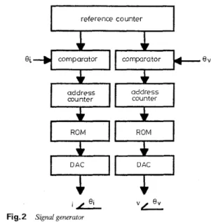
Signal generator: The SG is a digitally syn- thesised standard signal source [16-201. There are three SGs, for phases A, B and C, respectively. Each SG syn-460
thesises two separate low-level sinusoidal voltages with adjustable amplitudes and phase angles. As shown con- ceptually in Fig. 2, it consists of a phase reference counter, two comparators, two address counter, two ROMs with stored sine wave patterns, and two 16-bit digital-to-analogue converters (DACs). The phase angle reference counter repeatedly counts from 0 to 2n. When the reference angle reaches the currentholtage phase angle, the currentholtage-channel address coun- ter is triggered, and the ROM starts to output a digital sine wave pattern. The DACs convert the digital pat- tern into analogue signal.
At 60Hz the phase angle resolution is approximately lprad, and the amplitudes of i and v can be independ- ently set between OV and 15V by controlling the DC reference voltage supplied to another 16-bit DAC; this technique provides an amplitude resolution of approxi- mately 0.228mV.
3.1.2 Voltage/transconductance amplifier: Pre- cision power amplifiers are designed to boost the amplitudes and maintain the phase angle inherent in the S G s output signals [21-231. Owing to the precise requirements for voltage and current phase angles, a linear amplification technique is utilised. Switch-mode conversion is not feasible, because it is difficult to com- pensate for the phase lag of its output filtering. A developed VA boosts the low-level voltage reference to the nominal test range of OV - 300V RMS. A designed
IA converts the current-reference voltage signal into the test current. The test current ranges from -lOA to 10A. The designed bandwidth of these power amplifi- ers is 20kHz.
3.2 Programmable switching box
The PSB is mainly composed of several electromechan- ical relays. These relays can connect the PCGS, TUTs and the DMM following commands from the compu- ter. Hence, it directs the power path from the PCG to the TUT and transmits the transducer output to the DMM. Ten selectable channels are built into this PSB.
3.3 Digital multimeter
The DMM reads the DC output of the testing trans- ducer and relays it to the PC. A high-precision 71/2- digit multimeter is used. The accuracy is 5 (20 parts per million R
+
2 parts per million FS) at 23°C i. 1°C with a temperature coefficient of 12 parts per millionPC. 3.4 IEEE-488 interfaceData transmission between the PC, DMM, PSB, VAS, IAs and SGs is through an IEEE-488 connection.
3.5 Personal computer
The PC is the 'brain' of the CAACS. All the system operations are controlled by PC. It sends specified VI1
phase angle and amplitude to power condition genera- tors. The generated testing power condition is fed to the TUT through the PSB. Channel selection inside the PSB is controlled by the PC through the user interface. Transducer output is also routed through the PSB to the DMM. The DMM delays its receiving action for several seconds until the TUT output has stabilised. The length of this delay depends on transducer per- formance and is supplied by the PC. The PC receives the DMM output and compares it with the transducer specification that is stored in a PC database file in advance.
4 Software system design
This software was developed with three goals: to auto- mate the calibration procedure; to be user friendly; and to produce and manage calibration results. The soft- ware configuration and the kernel programs controlling all the system operations are described as follows:
The software configuration, as illustrated in Fig. 3,
consists of two levels: the system level and the applica- tion level. At the application level, a control kernel composed of a user menu and a procedure control pro- gram has been developed. These programs are specifi- cally designed to facilitate the calibration of power transducers.
system level MS-DOS shdl
A
v
ont!o! kernel.
application level 8 - -- user menu program ...mouse keydoard printer screen
Fig. 3 Software configuration
The user menu program is written in Turbo Vision Pascal with object-oriented programming construction. It is designed for users who are either familiar with or totally fresh to computer operations. A mouse or key- board can be used as the input device. Pop-up windows with various dialogue boxes are used to customise the calibration process.
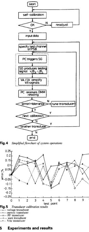
The procedure control program controls the system operation sequence. It is written in Microsoft C. A sim- plified flowchart describing the control procedure is shown in Fig. 4. If self-calibration is required, the oper- ator connects a null channel of the PSB and performs self-calibration using the normal calibration procedure. After that, the operator inputs other necessary routine data about this test work and chooses the method of calibration: single point, equally spaced multiple points, or fixed increments from zero to full scale.
Self-calibration is used to minimise inaccuracies orig- inating in the calibration system itself owing to ageing, temperature etc. It is optional before each calibration process. After that, the whole procedure is controlled by the PC via the screen interfacing with users. The specification data for testing transducers are required in advance. Channel selection inside the PSB for each transducer to be tested has to be specified. Then the PC sends the testing command to the power condition gen- erator. The SG and VAIIA produce and amplify testing sinusoidal V/I signals, respectively. The generated test- ing power condition is fed to the TUT through the channel in the PSB. Transducer output is also routed through the PSB to the DMM. The multimeter delays its receiving action for several seconds until the trans- ducer output has stabilised. The duration of the wait is determined by the PC. It depends on the transducer type and performance. The PC receives the DMM reading and compares it with the transducer specifica- tion. If the mismatch lies beyond the tolerance range,
IEE Proc.-Sci. Meas. Technol., Vol. 142, No. 6, November 1995
the transducer parameters are adjusted. The process is repeated until the mismatch becomes small enough. If necessary, this prcocess is repeated for other calibration points. For other transducers connected to the PSB, the whole procedure is applied to them, one by one.
self -calibration
specify test channel
of PSB m ... - ... i V A l I A amplify i ; VI1 signals j Pc receivesDMM reading \... ...
&
Fig. 4 Simplifiedflowchart of system operations
0.25 r
-0.25 -O
’
<
0 1 2 3 4 5 6 7 8 9 10
test point Fig. 5 Transducer calibration results
-*- voltage transducer
-
current transducer-x- PF transducer -+- watt transducer
-.-
VAr transducer5 Experiments and results
The objective of this Section is to illustrate how to set up a testing condition and to demonstrate the effective- ness of this calibration system. Inside the CAACS, each of three PCGs can work independently. One- or three phase power transducers can be calibrated by co-ordi- nating the PCGs. In all testing conditions, the single- phase voltage is 120V RMS and the current range is from -5A to +5A.
Tabie 1: Transducer specifications
Type Specification Tolerance limits Transducer
name
VAr FPK-211 input : 12OV 5A 60Hz f0.2%RO/PF+O.O5%RO
Watt FPW-211 Voltage FPVX Current F PAX Power factor FPPF output: 0- + I m A DC/ input : 120V 5A 60Hz output: 0- f l m A DCI
input : AC 0-150A +0.2%RO output : 4-20mA DC
input : AC 0-5A +0.2%RO output : 4-20mA DC input : 120V 5A 60Hz output : 4-12-20mA DC/ 0-f15OOW +0.2%RO/PF+O.O5%RO 0-+15OOW f0.25%FSf0.3 -1 .o-0-+I .o
Five transducers of different types, including voltage, current, watt, VAr and power factor transducers, are tested in the CAACS. Table 1 shows their specification data. The calibration results in graphical form are pre- sented in Fig. 5. Each transducer output curve is inside the specific tolerance error band specified in Table 1.
The uncertainty of the CAACS mainly comes from the PCGs. ADCs inside the SG may have nonlinear error, offset displacement error, gain displacement error etc. The power amplifiers may suffer profile dis- tortion and phase inaccuracy. With special design and implementation considerations for those points, the uncertainty of this system is kept within 200 parts per million.
6 Conclusions
A computer-aided automatic calibration system has been developed for the instrument calibration depart- ment of the Taiwan Power Company. It is specially designed for the use of power utilities. With the compu- ter-aided automation, a large portion of the original calibration work load is transferred to this system. One- or three-phase power transducers can be cali- brated using this system. The experimental tests give satisfactory results and illustrate the effectiveness of the developed system.
The main features of this system are its user-friendly interface and its capability to calibrate ten transducers using only one set-up. This system demonstrates how a computer-aided system can be used to promote quality and efficiency and reduce the work load of a calibra- tion department. The menu-driven software structure makes it easy to use. This reduces learning time and speeds the preparation of test procedures. The data- management capabilities of this software make this a complete system for preparing procedures, calibrating and managing the results.
7 Acknowledgment
The authors would like to express their gratitude for financial support from the Instrument Calibration Department of the Taiwan Power Company, Taiwan, under contract 81-S-32. 8 1 2 3 4 5 6 7 8 9 References
INOUE,T , YAMAMURA,K , and END0,M ‘Automatic cali- bration system for a laser power meter’, ZEEE Trans, 1985, IM- 34,pp 431436
LENTNER,K J , and FLACH,D R ‘An automatic system for AC/DC calibration’, IEEE Trans, 1983, IM-32, pp 51-56 BETHEA,M D , and ROSENTHAL,B N ‘An automated ther- mocouple calibration system’, ZEEE Trans, 1992, IM-5, pp 702- 706
OLDHAM,N M , PARKER,M E , and SMITH,A G ‘A high- accuracy IOHz - lMHz automatic AC voltage calibration sys- tem’, ZEEE Trans., 1987, IM-36, pp 883-887
SO,E ‘A microprocessor-controlled current-comparator-based DC voltage calibrator’, ZEEE Trans, 1987, IM-36, pp 291-295 TSAO, S H ‘Microcomputer-based calibration systems for varia- ble voltage dividers’, ZEEE Trans, 1983, IM-32, pp 169-173 SMITH,J A., and KATZMANN,F L ‘Computer-aided DMM calibration software with enhanced AC precision’, ZEEE Tvans ~
RINGEARD,D., and MALOEUVRE, M ‘CALIBRATE a soft- ware for control and calibration of electronic measurement devices’, ZEEE Trans, 1988, IM-37, pp 497-500
WOODS,D ‘Simplified calibration technique for general six-port reflectometer reauiring onlv two coaxial airline standard’, ZEE 1987, IM-36, pp 888-893
Proc AT 1983, 140, (5): pp 550-253
10 CLOTHIER, W.K., and MEDINA,L. ‘The absolute calibration of voltage transformers’, Proc ZEE, l957,104A, (15), pp. 204-214
11 BETTS.P J., CLOTH1ER.W K , and SM1TH.H A ‘Method for
the absolute calibration of current transformers’, IEE Proc A , 1982, 129, (5), pp 322-327
12 FIANDER,J R , and SMITH,A S ‘Voltage-transformer testing- set calibrator’, Proc IEE, 1975, 122, (6), pp 675-680
13 BESAG,E ‘Calibration of a reference capacitor using general- purpose precision instruments’, Proc IEE, 1977, 124, (9), pp 833-836
14 BETTS,P J ‘Two-stage current transformers in differential cah- bration circuits’, ZEE Proc A, 1983, 130, (6), pp. 324-328 15 SM1TH.F C . CHAMBERS.B . and BENNETT.J C . ‘Cahbra-
tion techniques for free space reflection coefficient measurements’, ZEE Proc A , 1992, 139, ( 5 ) , pp. 241-253
16 OLDHAM, N.M., LAUG, O.B., and WALTRIP, B.C.. ‘Digitally synthesized power calibration source’, ZEEE Trans , 1987, IM-36, DD. 341-346
17 OLDHAM,N M. ‘Power calibration standard based on digitally synthesized sinewaves’, ZEEE Trans, 1985, PAS-104, pp 3117- 3121
18 OLDHAM,N M and TURGEL,R.S ‘A power factor standard using digital waveform generation’, ZEEE Trans , 1981, PAS-100, pp 44354438
19 VASTRADE, C , VRE, R D , COUVREUR, M , and HUY- BRECHTS, R.. ‘Calibration of high accuracy wattmeters with a standard generator’, IEEE Trans, 1985, IM-34, pp 220-223 20 KINARD,J R., and HARRIS,L.A ‘Wattmeter calibration at
zero power factor using digitally generated sinewaves’, IEEE Trans, 1976, IM-25, pp. 547-549
21 TURGEL,R S , and OLDHAM,N M ‘High-precision audio-fre- quency phase calibration standard’, ZEEE Trans, 1978, IM-27, pp 460-464
22 LAUG,O B ‘A precision power amplifier for powdenergy cali- bration application’, ZEEE Trans, 1987, IM-36, pp 994-1000 23 LAUG,O B ‘A wide-band transcanductance amplifier for cur-
rent calibrations’, ZEEE Trans, 1985, IM-34, pp 639-643