Chia-Pin Liu
Graduate StudentDar-Zen Chen
Professor e-mail: dzchen@ccms.ntu.edu.twDepartment of Mechanical Engineering National Taiwan University Taipei, Taiwan 10660 R. O. China
On the Application of Kinematic
Units to the Topological Analysis
of Geared Mechanisms
Based on the concept of kinematic fractionation, a systematic method for the topological analysis of geared mechanisms is presented in this paper. It is shown that a geared kinematic chain (GKC) can be regarded as a combination of kinematic unit(s). By iden-tifying the embedded kinematic units, kinematic insight in the GKC can be exposed. The disclosed information leads to straightforward and promising rules to prevent redundant links. These rules form the basis of a by-inspection procedure to determine admissible assignments of the ground, input and output links in a GKC. Admissible assignments of the ground, input and output links of one degree-of-freedom 5 link GKCs are determined as an illustrative example. 关DOI: 10.1115/1.1352022兴
1 Introduction
In the conceptual design phase, type synthesis is regarded as a sequential process consisting of topological synthesis and topo-logical analysis关1兴. Topological synthesis is referred to as a pro-cedure to determine admissible topological structures of the de-sired mechanism, and topological analysis is aimed at determining the locations of ground, input and output links in a certain topo-logical structure.
Numerous studies have been performed on the topological syn-thesis of non-fractionated epicyclic gear trains共EGTs兲. Freuden-stein 关2兴 enumerated admissible graphs of one-dof, up to 5-link EGTs. Tsai关3兴 presented a generic approach to enumerate admis-sible graphs of one-dof, up to 6-link EGTs. Tsai and Lin 关4兴 modified the generic approach to enumerate admissible graphs of two-dof, up to 7-link EGTs.
In comparison with topological synthesis, research on topologi-cal analysis can be barely found. Olson, et al.关5兴 established the concept of coincident-joint graph and developed an exhaustive approach to determine possible locations of the ground, input and output links in one-dof, 5-link EGTs with both input and output links adjacent to the fixed link. However, additional redundancy check was required since the majority of their results contained redundant links. Hence, applications of the developed atlases from the topological synthesis are extensively limited.
For the design of geared mechanisms, avoiding redundant links is an important consideration to reduce the power loss and to enhance the compactness of the mechanism. Traditional ap-proaches to identifying the existence of redundant link共s兲 rely on deriving the kinematic relation between input and output links. Those links, which do not appear in the derived kinematic equa-tion, are determined as redundant links关5,6兴. However, this re-dundancy check becomes laborious for a complicated mechanism. Liu and Chen关7兴 proposed the concept of kinematic fraction-ation and a matrix-based method was developed to identify the type of fractionation of GKCs. They showed that over half of the one-dof, and all of the two-dof structurally non-fractionated GKCs can be fractionated via the concept of kinematic fraction-ation. However, this approach does not show the connecting con-dition among links and thus can not be applied directly to assign the locations of the ground, input and output links.
Based on displacement graphs 关2兴, the concept of kinematic units will be introduced in this paper to represent the basic kine-matic structure in a GKC. By identifying the kinekine-matic units and
the end vertices, admissible assignments of the ground, input and output links in a GKC can be obtained through a systematic ap-proach without generating any invalid assignment containing re-dundant links. Since the redundancy check is not required to ob-tain admissible results, this approach is much more efficient than the former one developed by Olson, et al.关5兴. As an illustrative example, admissible assignments of the ground, input and output links in one-dof, 5-link ground-actuated geared mechanisms will be determined. It is believed that the presented method acts as an efficient tool to harness the former developed atlases of EGTs, and can be applied to n-dof geared mechanisms as well.
2 Topological Structure of a GKC
Graph theory has been successfully used to represent the topo-logical structure of a geared mechanism separated from its func-tion. Some definitions are reviewed in the following:
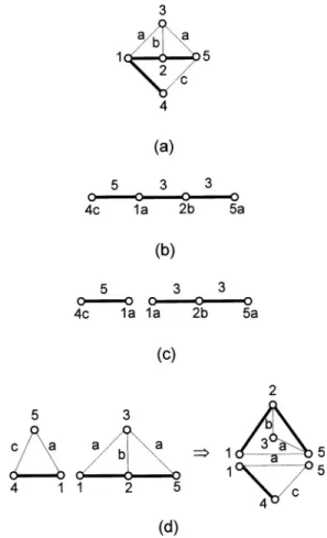
共a兲 Structural graph: The structural graph shows the topologi-cal structure of a GKC. In a structural graph, links are represented by vertices, gear pairs are represented by heavy edges, and turning pairs are represented by thin edges, which is labeled according to its axis orientation in space. Figure 1共b兲 shows structural graph 1400-1-7关2兴, which corresponds to a one-dof, 5-link gear train in Fig. 1共a兲.
共b兲 Displacement graph: A displacement graph expresses the topological structure of a GKC in an abbreviated form. The dis-placement graph of a GKC is obtained from its structural graph by deleting thin edges and transfer vertices, labeling each heavy edge with the corresponding carrier, and labeling each geared vertex according to the axis of the joint connecting the gear and the carrier关2兴. Figure 1共c兲 shows the displacement graph associated with Fig. 1共b兲.
共c兲 Structurally non-fractionated GKC: A GKC without any cut vertex in its structural graph or its pseudo-isomorphic graph共s兲 关4兴 is referred to as a structurally non-fractionated GKC.
Since a structurally fractionated GKC can be decomposed into non-structurally fractionated sub-chains by separating the cut ver-tex, only non-structurally fractionated GKCs will be discussed in this paper.
3 Concept of Kinematic Fractionation
Freudenstein关8兴 introduced the concept of fundamental circuit to represent the minimal kinematic structure in a structural graph. A fundamental circuit consists of two vertices representing a pair of meshing gears, a vertex representing the associated carrier, and the connecting edges. The kinematic relation in a fundamental Contributed by the Mechanisms Committee for publication in the JOURNAL OF
MECHANICAL DESIGN. Manuscript received Jan. 2000. Associate Editor: M. Raghavan.
circuit can be described by a fundamental circuit equation. In Fig. 2, vertices i, i⫹1 and k form a fundamental circuit and the asso-ciated fundamental circuit equation can be expressed as
i,k⫽ei⫹1,ii⫹1,k (1) wherei,kis the relative angular displacement between links i and k, and ei⫹1,iis the gear ratio between gears i⫹1 and i.
Also, vertices i⫹1, i⫹2 and k form another fundamental cir-cuit and the associated fundamental circir-cuit equation can be ex-pressed as
i⫹1,k⫽ei⫹2,i⫹1i⫹2,k (2) Since gear vertex i⫹1, and the carrier vertex k are common to both fundamental circuits, Eqs.共1兲 and 共2兲 have a common vari-able,i⫹1,k. Substituting Eq.共2兲 into Eq. 共1兲 yields
i,k⫽ei⫹2,i⫹1•ei⫹1,ii⫹2,k (3)
Similar substitutions can be repeated along the heavy-edged path. By repeating the substitution of fundamental circuit equa-tions, kinematic relation between two ends of the heavy-edged path can be described by an augmented fundamental circuit equa-tion. For instance, the relation between links i and i⫹n in Fig. 2 can be written as
i,k⫽ei⫹n,i⫹n⫺1•ei⫹n⫺1,i⫹n⫺2•¯ei⫹1,ii⫹n,k (4) It can be seen that the gear ratios in Eq. 共4兲 includes all the gears between link i and i⫹n, and thus it exposes the carrier, the ends and also the transmission path in an augmented fundamental circuit. In contrast to a fundamental circuit, which focused on the kinematic relation between only one gear pair, the concept of the augmented fundamental circuit provides a lucid way to group the links in a gear train and also provides a clear equation to lump the kinematic relations among the links. Hence, an augmented funda-mental circuit can be regarded as the basic kinematic structure in a GKC.
From the distribution of carrier共s兲, basic kinematic structure共s兲 in a GKC can be identified from its associated displacement graph according to the following procedure:
Step 1. Separate the displacement graph into connected
sub-graphs so that each sub-graph includes all the gear vertices asso-ciated with the same carrier.
In Fig. 1共c兲, each sub-graph contains only one carrier label and thus no further separation is required. Figures 3共a兲 and 共b兲 show respectively the structural graph and the displacement graph of graph 1400-1-4 关2兴. It can be seen that the displacement graph contains two carrier labels. Hence, Fig. 3共b兲 should be separated as shown in Fig. 3共c兲 in which each sub-graph has only one carrier label.
Fig. 1 Graph 1400-1-7. „a… the functional representation; „b…
the structural graph;„c…the displacement graph;„d…the KUs
Fig. 2 A typical KU with connected heavy-edged path
Fig. 3 Graph 1400-1-4. „a… the structural graph;„b… the dis-placement graph;„c…the separated displacement graph;„d…the KUs.
Step 2. Build gear-carrier pairs in each connected sub-graph by
adding a vertex representing the carrier, connecting the gear and carrier vertices with thin edges and labeling each thin edge with the axis orientation.
Left-hand sides of Fig. 1共d兲 and Fig. 3共d兲 show the results ob-tained from Fig. 1共c兲 and Fig. 3共c兲 respectively.
Step 3. Obtain kinematic units共KUs兲 by connecting the common
vertices in each sub-graph obtained from Step 2 with a thin edge. In Fig. 1共d兲, each sub-graph has already a thin edge connecting the common vertices 3 and 4. Hence, each connected sub-graph in Fig. 1共d兲 represents a KU which can be rearranged as shown on the right-hand side. On the left-hand side of Fig. 3共d兲, it can be seen that vertices 1 and 5 are common to both connected sub-graphs. One of the sub-graphs has already a thin edge between vertices 1 and 5 directly while another sub-graph uses a thin-edged path, 1-3-5, to connect vertices 1 and 5. It is known that the connection among vertices with thin edges having the same label can be rearranged arbitrarily without changing any kinematic characteristics关4兴. The procedure is called coaxial rearrangement. Hence, a thin edge can be relocated between vertices 1 and 5 since the path 1-3-5 has a unique axis label. The rearranged result is shown on the right-hand side of Fig. 3共d兲 in which each connected sub-graph represents a KU.
A KU not only shows the topological structure of an augmented fundamental circuit but also highlights the interface between two augmented fundamental circuits. Hence, the kinematic structures and the connecting relations in a GKC can be clearly exposed by decomposing a GKC into KUs
The end of each motion transmission path of the entire GKC is referred to as an end vertex. Since motion is transmitted along the heavy-edged path, it is obvious that an end vertex should be on the open end of the heavy-edged path. As a GKC contains more than one KU, the end of motion transmission of the entire GKC should take the connecting condition between KUs into consider-ation, and the end vertices can be identified according to the fol-lowing definition:
End vertex: An end vertex of a GKC is a vertex, which is on an
open end of the heavy-edged path of a KU but is not common to another KU.
As shown in Fig. 1共d兲, vertices 1, 3, 4 and 5 are on the open ends of the heavy-edged paths. Since vertices 3 and 4 are the common vertices between the two KUs, only vertices 1 and 5 are end vertices.
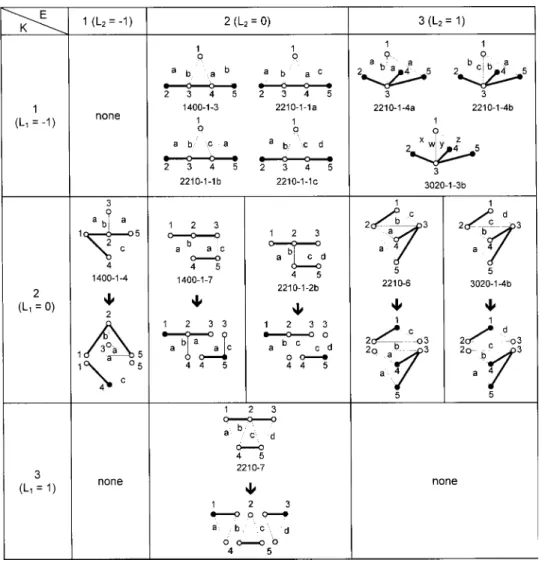
According to the above procedure, all the KU共s兲 and the end vertices contained in a GKC can be identified. The KU共s兲 and the end vertices of the thirteen one-dof, 5-link structurally non-fractionated GKCs关2兴 are shown in Table 1 in which K represents the number of KUs, E represents the number of end vertices, and each dark vertex represents an end vertex. It can be seen that seven of the thirteen GKCs have only one KU and thus are clas-sified as kinematically fractionated. For a kinematically non-fractionated GKC, the associated KU is identical to the GKC it-self. The remaining six GKCs have more than one KU and are classified as kinematically fractionated.
4 Topological Requirements of a Geared Mechanism The kinematic insight revealed by the KUs provides a substan-tial assistance to determine admissible locations of the ground, input and output links. In what follows, we shall confine the dis-cussion to ground-actuated mechanisms. The assignment of the ground, input and output links is assumed to satisfy the following basic requirements:
1 The input link is adjacent to ground.
2 The motion of every driven link is properly constrained by the input共s兲.
3 No redundant links.
4.1 Mobility Requirement. The input link and its support-ing link form an actuator pair关9兴. From the first requirement, each actuator pair should be assigned on a thin edge incident to the ground. Hence, we have
Axiom 1: The number of thin edges incident to the ground is
equal to or greater than the number of dof of the mechanism, F. The relative angular displacement between the actuator pair is used to determine the motion of other links. A link is said to be properly constrained if its motion can be determined according to the motion of actuator pair共s兲. With the concept of kinematic frac-tionation, the motion of a link is lumped with other links in the same KU. From Eq.共4兲, it can be seen that once the motion of an actuator pair is assigned in a KU, the motion of other links will be determined sequentially along the heavy-edged path. Note that as a KU has more than one actuator pair, the KU turns out to be overly constrained. Thus, we have
Axiom 2: A KU can contain at most one actuator pair.
With the single input, the motion of each link inside the KU is completely constrained. In addition, a mechanism with properly constrained motion should obey the following axiom:
Axiom 3: The total number of actuator pairs is equal to the
num-ber of dof of the mechanism, F.
4.2 Minimum Number of Output Link„s…. Based on a
GKC, a geared mechanism is developed such that the number of dof is equal to the number of inputs specified in advance. How-ever, the number of outputs is usually not taken into account. Hence, the topological structure of the GKC only ensures to pro-vide enough mobility but can not guarantee a proper kinematic structure to perform the specified function.
The ground, input and output links are said to be the ports of a mechanism. Let M be the number of ports in the mechanism. According to the statement in Axiom 3, M can be resolved as follows based on the fact that a mechanism can have only one ground link:
M⫽1⫹F⫹P (5)
where P is the number of outputs.
By viewing each KU as a sub-structure of the GKC, a KU should contain at least one of the ports to avoid redundancy. Thus, we have:
Axiom 4: The number of ports in a mechanism is greater than or
equal to the number of KUs in the associated GKC, i.e.
M⭓K (6)
A link becomes redundant if it has no contribution to transmit-ting motion from the input link to the output link. Since the end vertex represents a terminal of a transmission path, every end vertex in the GKC needs to be assigned as one of the ports to avoid forming redundant links. Hence, the concept of end vertices leads to the following axiom:
Axiom 5: The number of ports in a mechanism is greater than or
equal to the number of end vertices in the associated GKC, i.e.
M⭓E (7)
By substituting Eq.共5兲 into Eqs. 共6兲 and 共7兲 respectively and since a mechanism should have at least one output, the number of outputs in a GKC can be derived as:
P⭓Max.兵1,L1,L2其 (8)
where
L1⫽K⫺共1⫹F兲 and (9)
L2⫽E⫺共1⫹F兲 (10)
By examining the one-dof, 5-link GKCs in Table 1, it can be determined according to Eq.共9兲 that
L1⫽1⫺共1⫹1兲⫽⫺1
for kinematically non-fractionated GKCs (11a)
L1⫽2⫺共1⫹1兲⫽0
for kinematically fractionated GKCs with 2 KUs (11b)
L1⫽3⫺共1⫹1兲⫽1
for kinematically fractionated GKCs with 3 KUs (11c) From Eq.共10兲, it can be also determined that
L2⫽1⫺共1⫹1兲⫽⫺1 for GKC with 1 end vertex
(12a)
L2⫽2⫺共1⫹1兲⫽0 for GKC with 2 end vertices
(12b)
L2⫽3⫺共1⫹1兲⫽1 for GKC with 3 end vertices
(12c) By substituting the results of Eqs.共11兲 and 共12兲 into Eq. 共8兲, it can be concluded that the minimum number of outputs for all the one-dof, 5-link GKCs is one.
5 Procedure for Topological Analysis
Based on the requirements of admissible mechanisms, the pro-cedure to determine the locations of ground, input and output links in a GKC is developed as follows. For the purpose of dem-onstration, graph 1400-1-7 is selected as an illustrative example by assuming the number of output equal to one, and thus the number of ports, M, is equal to 3.
5.1 Assignment of the Ground Vertex. From Axioms 1 and 5, the requirements of an admissible location of the ground can be derived as follows:
R1: A vertex can be selected as the ground if the number of incident thin edges is equal to or more than the number of dof of the mechanism.
R2: A vertex is selected as the ground such that the number of end vertices, which are not used as the ground, is no more than M ⫺1.
According to R1 and R2, it can be seen that every vertex in graph 1400-1-7 is eligible to be the ground.
5.2 Assignment of the Input Link. In a ground-actuated mechanism, the requirements of admissible locations of input link共s兲 can be derived from Axiom 2 as follows:
R3: A vertex can be selected as an input if it is adjacent to the ground vertex with a thin edge.
R4: As more than one input link is required, actuator pairs should be assigned in different KUs.
In addition, another requirement for the input can be derived from R2 as follows
R5: The input vertices are selected such that the number of end vertices, which are not on the actuator pair(s), is no more than
According to R3, R4 and R5, the input link in graph 1400-1-7 can be selected according to different selections of ground verti-ces:
共1兲 Vertex 1 is the ground: It can be found that vertex 4 is adjacent to vertex 1 with a thin edge. In addition, a thin edge can be formed between vertices 3 and 1 by coaxial rearrangement. Since both of the two vertices satisfy R5, two admissible combi-nations of the ground and input links are obtained and can be expressed as关G; l兴⫽关1; 3兴 and 关1; 4兴.
共2兲 Vertex 2 is the ground: Vertex 4 is the only one vertex that is connected to vertex 2 with a thin edge. However, if vertex 4 is assigned as the input link, R5 can not be satisfied. Thus, no ad-missible results can be obtained by choosing vertex 2 as the ground.
共3兲 Vertex 3 is the ground: After coaxial rearrangement, it can be found that vertices 1, 4 and 5 are adjacent to vertex 3 with a thin edge. However, only vertices 1 and 5 satisfy R5. Thus, the admissible combinations of the ground and input links are ob-tained as关3; 1兴 and 关3; 5兴.
共4兲 Vertex 4 is the ground: Vertices 1, 2 and 3 are found to be adjacent to vertex 4 with a thin edge. However, only vertex 1 satisfies R5. Thus, the only one admissible combination of the ground and input links is obtained as关4; 1兴.
共5兲 Vertex 5 is the ground: The only one vertex connected to vertex 5 with a thin edge is vertex 3, which also satisfies R5. Thus, one admissible combination of the ground and input links is obtained as关5; 3兴.
5.3 Assignment of the Output Vertex. According to the requirement described in Eq.共7兲, admissible locations of output link共s兲 should meet the following requirements:
R6: Each end vertex, which is not on the actuator pair, is as-signed as the output link.
R7: In the case that all end vertices are on the actuator pair, any one of the other vertices can be assigned as an output link. R8: The output link(s) is selected such that each KU contains at least one of the ground, input and output links.
The output link in graph 1400-1-7 can be determined as fol-lows:
Case 1.关G; I兴⫽关1; 3兴,关1; 4兴,关3; 1兴 or 关4; 1兴: The re-maining end vertex is vertex 5. According to R6 and R8 admis-sible combinations of the ground, input and output links are determined as 关G; I; O兴⫽关1; 3; 5兴, 关1; 4; 5兴, 关3; 1; 5兴, and 关4; 1; 5兴.
Case 2.关G; I兴⫽关3; 5兴 or 关5; 3兴: The remaining end vertex is vertex 1. Thus, admissible combinations of the ground, input and output links are determined as关3; 5; 1兴, and 关5; 3; 1兴.
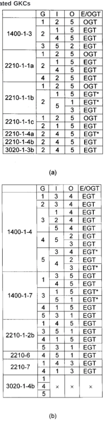
From Cases 1 and 2, six sets of admissible arrangements of the ports are obtained as listed in Table 2共b兲. Since these arrange-ments have more than one carrier, the associated mechanisms have at least one floating carrier. Hence, these configurations are all classified as EGTs.
Based on the above procedure, admissible assignments of the ground, input and output links for one-dof, 5-link kinematically non-fractionated and kinematically fractionated GKCs are ob-tained as shown in Tables 2共a兲 and 共b兲 with the number of output equal to one. It can be seen that only four ordinary gear trains 共OGTs兲 are obtained in which the unique carrier vertex is used as the ground link. It is also found that no ground-actuated mecha-nism with one output can be obtained from graph 3020-1-4b.
In Tables 2共a兲 and 共b兲, seven EGT configurations are marked with an asterisk. The input and output links in these configurations are both adjacent to the ground. In such configurations, the dis-tinction between the input and output links is unnecessary since the input and output links are topologically identical. By disre-garding the distinction between input and output links, four dis-tinct EGTs are obtained, which can be expressed as关G; (I/O)兴 ⫽关2; (1/5)兴 for graph 2210-1-1b, 关2; 共4/5兲兴 for graph 2210-1-4a, 关5; 共3/4兲兴 for graph 1400-1-4 and 关3; 共1/5兲兴 for graph 1400-1-7.
By comparing the above four EGT configurations with those results obtained by Olson, et al.关5兴, it can be found that the re-sults of both approaches come into agreement. However, the coincident-joint-graph approach uses an exhaustive method to generate fifty-four possible configurations, in which fifty configu-rations are found containing redundant link共s兲 after deriving the kinematic relation between input and output links. Hence, it is much more time-consuming with the coincident-joint graph ap-proach关5兴.
Table 2 Admissible †G; I; O‡ assignment of one-dof, 5-link GKCs.„a… kinematically non-fractionated GKCs;„b… kinemati-cally fractionated GKCs
6 Examples
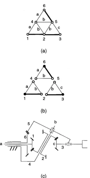
6.1 A Mechanism with Multiple Outputs. Figures 4共a兲 and 共b兲 show respectively the structural graph and KUs of the one-dof GKC, graph 6201-2关3兴. It can be observed that the GKC contains two KUs and four end vertices. From Eqs.共9兲 and 共10兲, it can be determined that
L1⫽2⫺共1⫹1兲⫽0 (13a)
L2⫽4⫺共1⫹1兲⫽2 (13b)
By substituting L1and L2into Eq.共8兲, it is found that at least
two output links should be assigned in the mechanism to prevent redundancy. By requesting 2 outputs, that is M⫽1⫹1⫹2⫽4, admissible assignments for the ports can be obtained according to the procedure in the previous section.
According to R2, it is known that the ground vertex should be selected such that the number of end vertices, which are not as-signed as the ground, is no more than M⫺1⫽3. Hence, the ground vertex can only be selected from vertex 3, 4, 5 or 6. However, from the symmetry of the structural graph, it can be found that vertices 3, 4, 5 and 6 are topologically equivalent. Thus, only one admissible location for the ground is obtained.
As vertex 3 is used as the ground, it can be seen that vertex 1 is connected to vertex 3 with a thin edge, and vertex 6 can also have a thin edge to connect with vertex 3 after coaxial rearrangement. However, from R5, it is known that the number of end vertices, which are not on the actuator pair should be no more than M ⫺1⫺F⫽2. Thus, the input link can only be assigned on vertex 6. With 关G; I兴⫽关3; 6兴, the remaining two end vertices should be used as the output links to prevent redundancy. Thus, a set of admissible assignment of the ground, input and output links are obtained as关G; I; O兴⫽关3; 6; (4, 5)兴. Figure 4共c兲 shows an ad-missible functional representation of the mechanism.
6.2 A Two-dof Mechanism. Figures 5共a兲 and 共b兲 show re-spectively the structural graph and KUs of the two-dof GKC, graph 4-1-1关4兴. It can be observed that the GKC contains three KUs and three end vertices. From Eqs. 共9兲 and 共10兲, it can be determined that
L1⫽3⫺共1⫹2兲⫽0 (14a)
L2⫽3⫽⫺共1⫹2兲⫽0 (14b)
According to Eq.共8兲, the mechanism requires at least one out-put link. By requesting one outout-put, that is M⫽1⫹2⫹1⫽4, ad-missible assignments of the ports can be obtained as follows.
From R1, it is known that the ground should be located on a vertex, which is incident with at least two thin edges. According to R2, it is known that the ground vertex should be selected such that the number of end vertices, which are not assigned as the ground, is no more than M⫺1⫽3. R1 and R2 indicate that the ground vertex can be selected from vertex 2, 4 or 5. The locations of input and output links are determined based on different selec-tions of the ground vertex:
Case 1. Vertex 2 is the ground: The input links can only be placed on vertices 4 and 5, which are connected to vertex 2 with a thin edge. However, both vertices are not valid locations for the input links according to R5. Thus, no admissible configurations can be obtained by selecting vertex 2 as the ground.
Case 2: Vertex 4 is the ground: Vertices 1, 2, 5 and 6 are con-nected to vertex 4 with a thin edge. According to R4 and R5, only
Fig. 4 Graph 6201-2.„a…the structural graph;„b…the KUs;„c…
an admissible mechanism configuration
Fig. 5 Graph 4-1-1.„a…the structural graph;„b…the KUs;„c…an admissible mechanism configuration
vertices 1 and 6 are valid locations for the inputs. Based on 关G; I兴⫽关4; (1, 6)兴, the remaining end vertex, vertex 3, is se-lected as the output according to R6. Thus, a set of admissible combination of the ground, input and output links is obtained as 关G; I; O兴⫽关4; (1, 6); 3兴.
Case 3: Vertex 5 is the ground: Vertices 2, 3 and 4 are con-nected to vertex 5 with a thin edge. However, no admissible lo-cations for the inputs can be obtained according to R4 and R5. Thus, no admissible configurations can be obtained by selecting vertex 5 as the ground.
From the above discussion, it is found that only one set of admissible assignment of the ground, input and output links can be obtained for graph 4-1-1. Fig. 5共c兲 shows an admissible func-tional representation of the mechanism.
Through the process of assigning the locations of the ground, input and output links, it can be found that the concept of KU and the locations of end vertices provide a designer with clear com-prehension of possible redundancy.
7 Conclusion
The concept of kinematic unit is introduced to determine the basic kinematic structures in a GKC. The identified kinematic units and end vertices depict the kinematic insight in the GKC and provide a clear guidance to prevent inducing redundant links. A systematic approach for the topological analysis of geared mecha-nisms is developed accordingly. From the approach, admissible
assignments of the ground, input and output links can be obtained directly by inspection without deriving the kinematic relations be-tween input and output links. Admissible assignments for one-dof, 5-link GKCs are obtained as an illustrative example.
References
关1兴 Erdman, A. G., and Sandor, G. N., 1991, Mechanism Design: Analysis and Synthesis, Vol. 1, Prentice-Hall, Englewood Cliffs, NJ.
关2兴 Freudenstein, F., 1971, ‘‘An Application of Boolean Algebra to The Motion of Epicyclic Drives,’’ ASME J. Eng. Ind., 93, Series B, pp. 176–182. 关3兴 Tsai, L. W., 1987, ‘‘An Application of the Linkage Characteristic Polynomial
to the Topological Synthesis of Epicyclic Gear Trains,’’ ASME J. Mech., Transm., Autom. Des., 109, No. 3, pp. 329–336.
关4兴 Tsai, L. W., and Lin, C. C., 1989, ‘‘The Creation of Non-fractionated Two-Degree-of-Freedom Epicyclic Gear Trains,’’ ASME J. Mech., Transm., Autom. Des., 111, pp. 524–529.
关5兴 Olson, D. G., Erdman, A. G., and Riley, D. R., 1991, ‘‘Topological Analysis of Single-Degree-of-Freedom Planetary Gear Trains,’’ ASME J. Mech. Des.,
113, pp. 10–16.
关6兴 Hsu, C. H., and Lin, Y. L., 1994, ‘‘Automatic Analysis of the Redundant Gears in Planetary Gear Trains,’’ Int. J. Veh. Des., 15, No. 5, pp. 402–415. 关7兴 Liu, C. P. and Chen, D. Z., 1999, ‘‘On the Embedded Kinematic Fractionation
of Epicyclic Gear Trains,’’ submitted to ASME Journal of Mechanical Design, Proceedings of the 1999 ASME Design Engineering Technical Conference, Paper No. DETC99/DAC-8660.
关8兴 Freudenstein, F., 1972, ‘‘Kinematics and Statics of a Coupled Epicyclic Spur-Gear Train,’’ Mech. Mach. Theory, 7, pp. 263–275.
关9兴 Davies, T. H., 1968, ‘‘An Extension of Manolescu’s Classification of Planar Kinematic Chains and Mechanisms of mobility M⭓1, Using Graph Theory,’’ J. Mec., 3, pp. 87–199.