An Efficient Video Object Segmentation Algorithm Based on Change Detection And Background Updating
13
0
0
全文
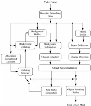
(2) algorithm [8][20], user must first define a high level. approaches, the segmentation algorithm based on the. semantic object of interest to be segmented and detect. change detection technology will be more efficient. the object’s boundary in key frame by way of manual.. than the other two types of segmentation algorithm. After then the extracted object of interest region is. which may be too computation-intensive to achieve. used to segment this object occurred in the video. the real-time purpose. The moving object obtained. sequences. The user interaction based algorithm can. always suffers from the uncovered background. give better segmentation results than automatic. situations, still object situation, light changing,. algorithm, but it may be unsuitable in real-time. shadow, residue background problem and noise due. applications due to the fact that an interest object. to the motion information is obtained by frame. needs to be specified by the user before the algorithm. difference. To overcome these problems and enhance. begins to execute.. the performance, this paper proposes an efficient. For this reason, automatic video object. video segmentation algorithm by using the change. segmentation algorithm have been developed and. detection and background updating technique. The. they are roughly classified into three types: the. proposed algorithm can be shown in figure 1. The. edge-feature based segmentation, spatial-temporal. Gaussian smooth is focused on reducing the noise. based. based. effect of input frame. Then, the change detection,. segmentation. The edge-feature based segmentation. object region detection, and background updating are. algorithm [9][12] utilize Canny edge detector to find. combined to extract a rough moving object. Finally,. edge information of each frame, and it can obtain. the accuracy of segmented object will be improved. correct segmentation object for stable moving-object,. through an efficient boundary refinement with an. but this approach must to acquire a absolute. appropriate amount of computations.. segmentation,. change. detection. background from video sequence and suffering a. 2. THE PROPOSED SEGMENTATION ALGORITHM. computation-intensive processing. In [10], based on the. spatial-temporal. segmentation. approach,. a. watershed transform is used to separate a frame into many homogeneous regions and then each region is. We proposed a video segmentation algorithm which. checked with the motion information. It brings about. is dedicated to separate the moving-object regions. over-segmentation due to sensitive to noise, but it can. from other parts of the scene by using of motion. give a good result of segmentation with high accurate. information. Our idea behind this algorithm is to. boundaries. This problem can be solved by. reduce the computational complexity. Thereby, the. smoothing texture of image content, but it will make. change detection is used to detect the difference. the performance of algorithm reduced. In the change. between previous frame and current frame instead of. detection based segmentation algorithm [2][3][13],. the motion estimation. Then, both frame difference. the position and shape of the moving object can be. mask and background subtraction mask obtained. detected by threshold the difference of two. from between difference background frame and. consecutive frames and them followed by a boundary. current frame are combined to distinguish the type of. fine-turning process with the spatial or temporal. object region in object region detection phase, in. information to improve the result of segmentation.. order to overcome the problems of uncovered. Basically speaking, for the above three. background and still object. Therefore, we construct 2.
(3) and maintain an updating background reference from the previous still object mask, which is used due to a static object or a region where moving object shift out their position are must to be renewed. Therefore, our approach, is aimed at the stationary object of a scene since the information of stationary object of a scene is more stable to make the constructed background to reliable and conform human visual perception. Because the background change owing to camera motion can be compensated by global motion estimation and compensation [13], the input sequence to our algorithm will be assumed to have been correctly compensated and thus the background is stationary. Finally, we also propose a novel object Figure 1. Block diagram segmentation algorithm.. boundary refinement technology to improve the boundary of object to make the accuracy of. of. the. proposed. segmented object to be increased. Also, the complexity in this process can be reduced. The details of each module in the proposed algorithm, as shown in figure 1, will be discussed in the following. (a). (b). subsections. 2.1. Frame difference (c) The frame difference technique [1][15] which means. Figure 2. (a) The Lerry sequence at frame #64; (b) The Lerry sequence at frame #65; (c) The difference frame between (a) and (b).. the difference between two successive frames. It often. is. utilized. in. change. detection. based. segmentation algorithm because of the effectiveness. detection, which discussed in next subsection.. is conformable to our need. The difference frame. Moreover, the module of background subtraction in. includes two parts: foreground part and background. our algorithm is performed by differencing current. part. The value on foreground area brings more. frame and background frame. This step is very. higher than the background area because of the. similar to the difference frame. Let f t −1 (i, j ) and. foreground region corresponding to moving region. f t (i, j ) denote the video frame on different time. when. background. region. corresponding. to. instant, respectively, the difference frame can be. non-moving region. Besides, the difference value on. achieved by the following equation:. background area is not zero due to the environmental. DIt (i, j) = ft (i, j) − ft −1 (i, j). effects, e.g., light change or noise effect. Hence, the. (1). external effect will lead the pixel in background part. Fig. 2 shows the example of difference frame for. be dis-classified into foreground part in change. Lerry sequence. 3.
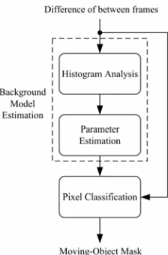
(4) 2.2. Change detection This major function of change detection is kernel operator in segmentation algorithm. The goal of change detection is to separate the difference frame into change region and unchange region, according to a threshold obtained from background estimation. In the reported research [1] which take the unchanged region of resulted change detection in previous frame as background part in the current frame. However, if the noise is introduced, this method will involve. Figure 3. Block diagram of the change detection.. estimated error in the current frame and the following 35000 N um ber of grayleve. frame in video sequence. In our approach, the histogram-based change detection is proposed that is constructed from difference frame. Figure 3 shows the proposed block diagram of change detection, which adopts histogram-based statistic method. First,. 30000 25000 20000 15000 10000 5000 0. the parameter of background model is estimated from. 1. 50. 99. 148. 197. 246. Graylevel. difference frame. Second, the pixel will be classified. Figure 4. The histogram distribution of figure 2(C).. according to statistic parameter obtained from previous phase. The detail of this process will be described in the following subsection.. 2.2.2. Parameters estimation 2.2.1. Histogram analysis Generally, the model of background region of the The histogram is constructed from difference frame,. difference frame can be regarded as Gaussian. which can provide information of the gray-level. distribution due to the noise effect existed between. distribution to analyze the characteristic of the. inter-frames. Hence, the mean and standard deviation. difference frame. Let His ( p ′) be the maximum gray. for the background model within a window, denoted. of bin at p ′ position of the histogram. To extract. as µb and stdb , respectively, need to be acquired.. more informations about the background, both. Firstly, the value of mean. His ( p ′) and p ′ need to be obtained and them such. deviation stdb , will be calculated at the site of. two values will be used in the following estimation of. p ′ with window size N . Then, µb and stdb will. µb and standard. the background model. Figure 4 shows the gray-level. be. distribution of difference frame for figure 2.. µ w and std w , which can be described in the following. obtained. equation:. 4. by. averaging. those. values. of.
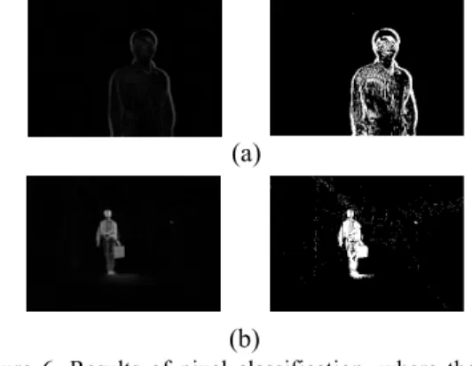
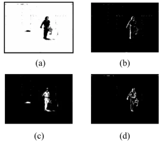
(5) std wi ( p ′) =. 1 N ∑ wi ( j ) N j =1. 18 16 14. Threshold. µ wi ( p ′) =. 1 N 2 ∑ [ wi ( j ) − µ wi ( p ′)] N j =1. 12 10 8 6 Lerry. 4. for i = 1, 2,..., His ( p ′). Hall Monitor. 2 0 1. µb =. σb =. 17. 25. 33. 41. 49. 57. 65. 73. 81. 89. 97. Frame Number. 1 his ( p′) ∑ µ wi ( p ′) his ( p ′) i =1 1 his ( p′) ∑ std wi ( p ′) his ( p ′) i =1. 9. Figure 5. Threshold curve for Hall Monitor and Lerry sequence.. (2). (a). 2.2.3. Pixel classification The pixel classification will classify the pixel on the difference frame into the change region or unchanged. (b). region according to the parameter of background. Figure 6. Results of pixel classification, where the left image is the frame difference and the right image is thresholded binary image for (a) Lerry sequence and (b) Hall Mointor sequence.. model, which can be described as if (| DF (i, j ) − µb |> c ∗ stdb ) then foreground pixel. Table 1. Object Region Detection Rule. else background pixel. (3) Region. Background. Frame. where DF (i, j ) is difference frame, and c is a. Description. SubtractionMask. DifferenceMask. constant.. Background. OFF. OFF. Uncoveredbackground. OFF. ON. Still region. ON. OFF. Moving region. ON. ON. Based on prior description, the threshold curves for Hall Monitor and Lerry sequence are shown in figure 5 and results of pixel classification are shown in figure 6, when constant value is 10.. corresponding pixel position of both background. 2.3. Object region detection. subtraction mask and frame difference mask. This case implies that there will be no any moving object. The object region detection step, it is used to detect. existed in the region. If only the frame difference. object region part in our algorithm. Table 1 lists the. mask-bit is detected as change, but unchange for the. criteria for distinguishing the region, where “OFF”. background subtraction mask-bit, the pixel is. and “ON” mean the pixel on frame difference (or. classified into the uncovered background region. This. background subtraction) mask to be the unchanged. problem is also critical issue for traditional change. and changed, respectively. A pixel is recognized as. detection algorithm. Since both the uncovered. the background region if there is “OFF” in the. background region and the moving region have 5.
(6) significant luminance change, distinguishing the difference between two regions is very difficult if only the frame difference mask is available. On the (a). other hand, one of the problems is that the object may. (b). Figure 9. Non-static region effect. (a) Still region mask; (b) Static part region of moving-object is removed.. stop moving temporarily or move very slowly. This situation, namely still object case, the motion information disappears if we use the frame difference mask only. However, the background subtraction information is adopted in our algorithm so that this case can be discriminated from object mask. The final case describes the moving region identification with “ON” for the both frame mask, i.e., a pixel is part of moving region if the pixel is detected as change by both. frame. difference. mask. and. background. subtraction mask checking processes. Figure 7 shows the results of object region detection. Figure 8. Block diagram of background updating.. 2.4. Background Updating Basically, the major function of background updating is to renew a scene when moving-object shift out their original positions or its state is transformed to standstill. In the reported researches [4][6][16], a. (a). (b). (c). (d). frame difference mask is fed into a kalman-filter to estimate the background needing to be updated. But this causes a large burden of computations since the kalman gain matrix requires to be updated frequently. Besides, this approach can’t overcome the situation. Figure 7. The results of object region detection for Hall Monitor sequence. (a) Background region; (b) Uncovered background region; (c) Still region; (d) Moving region.. that the moving object occurs on the first frame of the video sequence captured. To reduce computation for a real-time purpose, our method use previous still. 2.4.1. Non-static region elimination. region mask to construct and update background information. The block diagram of background. The input of background updating is still region mask. updating can be illustrated in figure 8.. which acquired from object region detection step. In general, the still region mask may contain the following three types of region: real still-region, light change, static part region of moving object. Based on our scheme of background updating, we hope the still 6.
(7) region mask that only involves real still-region and light change among these regions. In order to realize this purpose, the concept of region adjacent graphic can be utilized to solve this problem. Besides, we. (a). find a fact that if a region identified as the static part. (b). Figure 10. Result of background updating. (a) Weather #255; (b) The updated background.. region of moving object, it will connect to the region of moving region mask. Then, this region will be removed from still region mask. Thus the rule can be used to decide the region whether is the static part region of moving object or not. Figure 9 shows this. (a). situation when Sth is 150.. Figure 11. Background updating of meeting room sequence. (a) Meeting room sequence at. 2.4.2. Updating selector The. non-static. frame #350; (b) The updated Background at. region. elimination. frame #350.. described. previously which will be fail when a moving object. 2.4.3 Background Updating. existed at beginning of video frames due to the moving object region connect with a region where. The basic strategy of background updating is that if a. moving objects shift out their original positions.. pixel is marked as change on. Hence, the entire connecting region will be removed. increased by one; otherwise, the corresponding pixel. problem can be solved by using absolute background. is cleared as zero. Thus, each pixel value in the. detection to decide whether the moving object existed. stationary map indicates the change number of the. in beginning of video frames or not, for each pixel. corresponding pixel in the previous consecutive. site ( i, j ) , the four-order moments [14] md′ ( i, j ) is. frame. This strategy of background updating is. evaluated on a moving window of N w = 9 elements. described as. of the inter-frame difference d1, n (r , c) between first. ⎧⎪SM ( i, j ) +1, SMt ( i, j ) = ⎨ t −1 ⎪⎩0, If ( t = 1). frame and nth frame. 1 Nw. 1 mµ (i, j ) = Nw. ∑. ( r , c )∈w ( i , j ). ∑. ( r , c )∈w ( i , j ). (d1, n (r , c) − mµ ) d1, n (r , c). 4. (4). ⎧⎪ f t ( i , j ) , BI t ( i , j ) = ⎨ ⎪⎩ BI i −1 ( i , j ) ,. (6) if SM t ( i , j ) = Fth otherwise. where SM is stationary map, BI is the background. variance of background of d1, n (r , c) .. information, and Fth is a pre-defined constant. Figure 10 and figure 11 show the example for background (5). updating when Fth is 5 for Weather sequence and. ⎪⎧ ρ + 1 if ( m d′ > 75 * σ B ) otherwise ⎪⎩ ρ. ρ =⎨. otherwise. BI t ( i , j ) = f t ( i , j ). decided in following procedure, where σ B denotes if ρ > S th otherwise. if RSt ( i, j ) is change pixel. else. Finally, the output of updating selector can be. ⎧ sr , RS = ⎨ ⎩ NSRE ( sr ),. RS map; the. corresponding value in the stationary map is. so that no information used to renew a scene. This. md′ (i, j ) =. (b). 2. Meeting room sequence, respectively. 7.
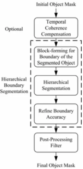
(8) 2.5. Object boundary refinement technology The coarse object region can be generated, that is, the union of moving region mask and still region mask, called as initial object mask. However, in practically, the characteristics and behavior of moving object are often not reliable and the environmental effect is also introduced. These phenomena will be a critical issue for affecting the accuracy of object boundary. Thus the proposed object contour refinement process will be used to improve the accuracy of the segmented object,. which. includes. temporal. Figure 12. Block diagram of object boundary refinement.. coherence. compensation, hierarchical boundary segmentation, and post-processing filter. The block diagram of boundary refinement is shown in figure 12. (a). 2.5.1. Temporal coherence compensation. (b). Figure 13. Temporal coherence compensation for Akyio. (a) initial object mask at frame # 29; (b) After using temporal coherence compensation for (a).. The goal of this process is to solve the problem of the fragmentary region of object because the motion information is not significant on object region when the object moves slowly or stops temporally. Generally speaking, the nature video signal exist high. (a). correlation between inter-frames, thereby, this feature. (b). Figure 14. Block-froming for boundary of the segmented object in the Thor sequence. (a) Initial object mask of frame #70. (b) Object mask fill and block division of (a).. can be used to compensate the fragmentary region of object through taking several frames of the initial object mask into count. The example can be shown in figure 13.. a constant λ , the block is regarded as non-moving, and eliminated from the object region, this procedure. 2.5.2. Hierarchical segmentation. of hierarchical segmentation can be shown as if (VBi < VDiff (G ( ft ),G ( ft −1 )) + λ ). The proposed hierarchical segmentation which is. the block is removed. process of block based so that initial object mask. else. must first be separate into block whose size is 16 × 16. the block is kept. and fill them before this functions executed, which shown in figure 14. We calculate the variance of the. if (blocksize = 16). boundary block, denoted as VBi , if the variance is. λ=2 else if (blocksize = 8). smaller than a threshold which obtained by difference. λ = 1.5. of gradient of previous frame and current frame plus 8.
(9) else if (blocksize = 4). λ =1 else if (blocksize = 2) λ = 0.5. (7) (a). (b). Repeating the procedure for all sub-block’s along the boundary until the non-moving sub-blocks are all removed. We can further divide the sub-block into (c). 8 × 8, 4 × 4, and then 2 × 2, then more compact boundary can be obtained consequently, see figure 15. (d). 2.5.3 Object boundary refinement. (e). Figure 15. Hierarchical segmentation for Weather sequence. (a) Object mask fill and block division at frame #22; (b) The block size is 16 × 16; (c) The block size is 8 × 8; (d) The block size is 4 × 4; (e) The block size is 2 × 2.. By way of the above step, a stable boundary of object can be obtained. However, interior of object will be erosion due to effect of hierarchical segmentation introduced and the thick background region still exited around the sharp of object. For first question, we can find the region where is non-union between initial object mask and hierarchical segmentation. (a). mask, then, if the value of gradient within this region. (b). Figure 16. Remove effect of hierarchical segmentation. (a) The effect of hierarchical segmentation at frame #111; (b) After compensating the effect for (a).. is larger than a threshold, the corresponding pixel will be compensated to hierarchical segmentation mask, it can be shown in figure 16. In addition, the problem of thick background which closes to sharp of object. will. make. the. compression. ratio. of. object-based compression to be reduced. Therefore, we use strategy of region growing to remove this area,. (a). (b). (c). (d). and the seed obtained through applying the Laplacian operator on hierarchical segmentation mask. This result is illustrated in figure 17. Figure 17. Remove the background region of the boundary by region growing. (a) The result of hierarchical segmentation with block 2 × 2; (b) The seed pixels of region- growing; (c) The grown region using seeds of (b); (d) The result of eliminating (c) from (a).. 2.6. Post-processing filter Up to now, the obtained object mask is nearly real object mask, but some noise is still existed in region mask regions because of irregular object motion and camera noise. 9.
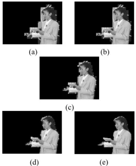
(10) Also, the boundary may not be very smooth. Therefore, there are two parts in post-processing filter: noise. region. elimination. and. morphological. smoothing processing, which will be described as. (b). (a). follows. 2.6.1. Noise Region Elimination. (c). We use the connected components algorithm [21] on. Figure 18. Post-processing: (a) the object mask after hierarchical segmentation; (b) the object mask after noise elimination; (c) the object mask after close-open operation.. the object mask to mark each isolated region, Then, we can remove the isolated region by considering their area. If the area of a region is small, it may be a noise region and can be eliminated from object mask. 2.6.2. Morphological Smoothness Processing. (a). (b). (c). (d). (e). (f). After removing the noise regions, the close and open operations [11] of morphological processing are employed to smooth the boundary of object with a 3 by 3 structuring element. Based on such a post-processing, the object mask is so refined that a better object mask with the more complete boundary. Figure 18 describes the post-processing, in which the subfigure. (b). shows. an. object. mask. after. noise-eliminating on subfigure (a) which obtained. Figure 19. Initial segmentation results for Weather at (a) frame #28; (b) frame #243; for Akyio at (c) frame #30; (b) frame #130; and for Thor at (e) frame #72; (f) frame #100.. from object boundary refinement step and then the morphological close-open operation is employed on the mask of (b) to yield a final object mask, as shown. algorithm. A reliable objective criterion, called spatial. in (c).. accuracy, is presented in section 3.1 to evaluate the. 3. EXPERIMENTAL RESULTS. segmentation result. Finally, in section 3.2, the segmentation results are presented to give subjective. In this section, we will demonstrate the experimental. evaluation this algorithm, and objective evaluation in. results of the proposed video segmentation algorithm.. spatial accuracy is also shown.. The simulation results show that this algorithm can 3.1. Spatial accuracy evaluation. give accurate video segmentation results for the tested video sequences, and also solve both problems of shadow and residual background region which. A reliable objective criterion [14], called spatial. existed in conventional video segmentation. accuracy, is presented to evaluate the segmentation 10.
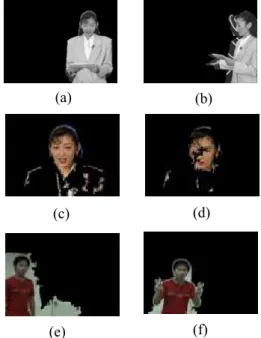
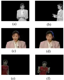
(11) results which measure the distortion of the algorithm by accumulating the distortion area then subtracted by one. Spatial accuracy evaluation can be described (a). (b). (c). (d). (e). (f). as. Spatial accuracy = (1−. ref seg ∑ Mt (r, c) ⊕ Mt (r, c). ( r , c). ref ∑ Mt (r, c). ) ×100%. (8). ( r ,c ). where M. ref t. ( r , c ) is. ideal alpha map, M. seg t. ( r , c ) is. final object mask generated with this algorithm and ⊕ is exclusive OR.. 3.2. Simulation. Figure 20. The results after executing object boundary refinement process for Weather at (a) frame #28; (b) frame #243; for Akyio at (c) frame #30; (b) frame #130; and for Thor at (e) frame #72; (f) frame #100.. This algorithm uses Weather, Thor and Akyio sequences. for. simulation.. In. figure. 19,. the. segmentation results in initial object region for them. 100 99 Spatial Accuracy (%). are shown. For Weather, which has large motion and residual background region exited, and for sequence Akyio, which has only slight motion so that can not give satisfied results of segmented object region, as. 98 97 96 95 94 93. shown in figure 19(a)-(d). In figure 19(e)(f), the. 1. 50. 99. 148. 197. 246. 295. Frame Number. shadow affects the sequence Thor. In figure 20, the. (a). segmentation results corresponding to figure 19 after. 99.8 Spatial Accuracy (%). object boundary process applied. The phenomenon of residual background region has been removed in Weather, as shown in figure 20(a)(b). In figure 20(c)(d) illustrates the problem of fragmentary object. 99.6 99.4 99.2 99 98.8 98.6 98.4 98.2. can be overcome, and the shadow effect for Thor. 1. 25. 49. 73. 97. sequence is also eliminated, as shown in figure. 121 145 169 193 217 241 265 Frame Number. 20(e)(f).. (b). 100 99 Spatial A ccuracy (%). Spatial accuracy chart for sequence Weather, Thor, and Akyio are shown in figure 21. From figure 21, we can find out that the spatial accuracy for them can be hold above 95%, which means the accuracy is quite. 98 97 96 95 94 93 92. high, and human eye will not pay attention to such. 1. small error.. 20. 39. 58. 77. 96. 115. 134. 153. 172. Frame Numer. (c) Figure 21. Spatial accuracy curve for (a) Weather; (b) Akyio; (c) Thor.. 11.
(12) 4. CONCLUSIONS. [3]. Shao-Yi Chien, Shyh-Yih Ma, and Liang-Gee Chen, “Efficient Moving Object Segmentation Algorithm. In this paper, we propose an efficient video. Using Background Registration Technique,” IEEE. segmentation algorithm based on change detection. Trans. on Circuits Syst. Video Technol., vol. 12, no. 7,. and background updating. Because of no complex. pp. 577-586, 2002.. operator is adopted in our algorithm and the simple. [4]. Da-Shan Gao, Jie Zhou, Le-ping Xin, “A Novel. change detection is used to obtain the motion. Algorithm of Adaptive Background Estimation,”. information, thus the effect of proposed method can. IEEE International Conference on Image Processing,. be increased greatly. Besides, the proposed non-static. vol. 2, pp. 395-398, Oct 2001.. region elimination can remove the moving region. [5]. Rafael C. Gonzalez and Richard E. Wood, Digital. from still region mask, it will more correctly make. Image Processing, 2Ed. New Jersey: Prentice Hall,. the background updating to renew a scene. Finally, a. 2002.. novel. object. boundary. refinement. method. is. [6]. Stefan Huwer, “Adaptive Change Detection for. presented which in order to eliminate the shadow. Real-Time. effect or light change, and solve the residual. International Workshop on Visual Surveillance,. background problem. After the process of object. pp.37-46, July 2000.. boundary refinement is applied, the quality of our. [7]. Surveillance. Applications,”. IEEE. R. M. Haralick and L. G. Shapiro, Computer and. method is already kept above 95%, and the time cost. Robot Vision. Reading, MA: Addison-Wesley, 1992,. is small than the conventional temporal-spatial based. pp. 28-48.. video segmentation algorithm. From the experimental. [8]. Munchurl Kim, J. G. Jeon, J. S. Kwak, M. H. Lee, C.. results, it reveals that the proposed segmentation. Ahn, “Moving object segmentation. algorithm. sequences by user interaction and automatic object. will. be. more. attractive. the. other. algorithms.. in video. tracking,” Image and Vision Computing, vol. 19, pp. 245-260, 2001.. 5. REFERENCES. [9]. C. Kim and J. N. Hwang, “Fast and Automatic Video Object Segmentation and Tacking for Content-Based Application,” IEEE Transaction on Circuits and. [1]. T. Aach, A. Kaup and R. Mester, “Statisticl. System for Video Technology, vol.12, no. 2, pp.. model-based change detection in moving video,”. 122-129, 2002.. Signal Processing, vol. 31, pp.165-180, Mar. 1993. [2]. [10]. Munchurl kim, Jae Gark Choi, Daehee Kim, Hyung. Shao-Yi Chien, Yu-Wen Huang, Bing-Yu Hsieh,. Lee, Myoung Ho Lee, Chieteuk Ahn and Yo-Sung. Shyh-Yih Ma, and Liang-Gee Chen,“Fast Video. Ho,. Segmentation Algorithm with Shadow Cancellation,. Segmentation of Moving Object in Image Sequences. Global. Adaptive. Based on Spatio-Temporal Information,” IEEE Trans.. Threshold Techniques,” IEEE Trans. on Circuits and. on Circuits Syst. Video Technol., vol.9, no. 8, pp.. System for Video Technol., vol. 6, pp. 732-748, no. 5,. 1216-126, Dec. 2002.. Motion. Compensation,. and. Oct. 2004.. 12. “A. VOP. Generation. Tool:. Automatic.
(13) [11]. Weiping Li, Jens-Rainer Ohm, Mihaela van der. International Conference on recent Advances in. Schaar, Hong Jiang, Shipeng Li “The MPEG-4. Mechatronics, ICRAM'95, pp. 193-199, 1995.. Video Standard Verification Model version 18.0,”. [12]. [17]. ISO/IEC JTC1/SC 29/WG 11 N3908, Jan. 2001.. model,”IEEE Trans. on Circuits Syst. Video Technol.,. Thomas Meier, King N.Ngan,“Video Segmentation. vol. 7, pp. 19-31, Feb. 1997.. for Content-Based Coding,”IEEE Trans. on Circuits. [13]. [18]. representation of image and video: Segmentation. pp.1190-1203, Dec. 1999.. tool for multimedia services,” IEEE Trans. on. Roland Mech and Michael Wollborn, “A noise robust. Circuits Syst. Video Technol., vol. 9, pp. 1147-1169,. method for 2D shape estimation of moving object in. Dec. 1999. [19]. Signal Processing, vol. 66, pp. 203-217, 1997.. Moving. Object. and. [20]. Candemir Toklu, A. Murat Tekalp, and A. Tanju. Background. Erdem, “Semi-automatic video object segmentation. Sepatation,” Signal Processing, vol. 66, pp. 219-232,. in the presence of occlusion,” IEEE Trans. on. 1998.. Circuits Syst. Video Technol., vol.10, no. 4, pp.. Jinhui Pan; Chia-Wen Lin; Chuang Gu; Ming-Ting. 624-629, June 2000.. Sun, “A robust video object segmentation scheme. [21]. with prestored background information,” Circuits. Symposium on Volume 3,. A. M. Tekalp, Digital Video Processing, Prentice Hall PTR, 1995.. and Systems, 2002. ISCAS 2002. IEEE International. [16]. Linda G. Shaprio and George C. Stockman, Computer Vision, Prentice Hall, 2001, pp. 149-152.. A. Neri, S. Colonnese, G.. Russo, P. Talone, “Automatic. [15]. P. Salembier and F. Marques, “Region-based. and System for Video Technol., vol.9, no. 8,. video sequence considering a moving camera,”. [14]. T. Sikora,“The MPEG-4 video standard verification. [22]. 26-29 May 2002. M. Wollborn and R. Mech, “Refined Procedure for Objective evaluation of Video Object Generation. Page(s):803 – 806.. Algorithm,”. Christof Ridder, Olaf Munkelt and Harald Kirchner,. M3448, Mar. 1998.. “Adaptive Background Estimation and Foreground Detection using Kalman-Filtering,” Proceedings of. 13. Doc.. ISO/IEC. JTC1/SC29/WG11.
(14)
數據
+5
相關文件
Light rays start from pixels B(s, t) in the background image, interact with the foreground object and finally reach pixel C(x, y) in the recorded image plane. The goal of environment
¾ Relocation, which modifies the object program so that it can be loaded at an address different from the location originally specified.. ¾ Linking, which combines two or
JRE (Java Runtime Environment): for users, JVM + basic libraries JDK (Java Development Kit): JRE + compilers + ... —jdk-6u12-windows-i586-p.exe or other platform
OOP: organized DATA + organized code (ACTION) using classes as the basic module. action are closely coupled
Because simultaneous localization, mapping and moving object tracking is a more general process based on the integration of SLAM and moving object tracking, it inherits the
this: a Sub-type reference variable pointing to the object itself super: a Base-type reference variable pointing to the object itself. same reference value, different type
Note that this method uses two separate object variables: the local variable message and the instance field name.. A local variable belongs to an individual method, and you can use
synchronized: binds operations altogether (with respect to a lock) synchronized method: the lock is the class (for static method) or the object (for non-static method). usually used
