A
Fast
Crosstalk-
and
Performance-Driven Multilevel Routing
System
Tsung-Yi
Ho',
Yao-Wen Chang2: Sao-Jie Chen2!
and
D.
T.
Lee3
Depamnent of Electrical Engineering, National Taiwan Univeniry, Taipei, Taiwan'
Graduate lnstiNte of Electronics Engineering and Department of Electrical Engineering, National Taiwan University, Taipei, Taiwan' Institute of Information Science, Academia Sinica, Taipei, Taiwan'
Abstract
In
tlus
paper, we propose a novel framework for fast multilevel routing considering crosstalk and performance optimization. To han- dle the crosstalk minirmzation problem, we incorporate an intermediate stage of layerltrack assignment into the multilevel routing framework. For performance-driven routing, we propose a novel minimum-radius minimum-cost spanning-uee (MRMCST) hewistic for global routing. Compared with the state-of-the-art multilevel routing. the experimental results show that our approach achieved a 6 . l X runtime speedup, re- duced the respective maximum and average crosstalk (coupling length) by about 30% and 24%. reduced the respective maximum and average delay by about 15% and 5%. and resulted in fewer failed nets.1
Introduction
With decreasing feature sizes, higher clock rates. and increasing in- terconnect densities, crosstalk has become a major concem of compa- rable importance to area and timing in IC design. Crosstalk profoundly affects the circuit performance in veri deep submicron (VDSM) tech- nology: it is introduced by a coupling between two neighboring wires.
For example. two adjacent wires form a coupling capacitor. A voltage
or a current change on one wire can thus interfere the signal
on
the other wire. Crosstalk is an unwanted variation which makes the behavior of a manufactured circuit deviate from the expected response. The delete- rious influences of crosstalk can be classified into two'categories. One is malfunctioning, which makes the logic values of circuit nodes differ from what we desire; the other is timing change, which is caused by switching behavior. Therefore, in addition to routability and timing per- formance. crosstalk minimization should also be considered in VDSM router design.Traditionally. the complex routing problem is often solved by us- ing the two-stage approach of global routing followed by detailed rout- ing. Global routing first partitions the routing area into tiles and de- cides tile-to-tile paths for all nets whde detailed routing assigns actual tracks and vias for nets. Many routing algorithms adopt a flat framework of finding paths for all nets. Those algorithms can be classified into sequential and concurrent approaches. Early sequential ranting algo-
rithms include maze-searching approaches I181 and line-searching ap- proaches [14J, which route net-by-net. Most concurrent algorithms a p
ply network-flow [I] or linear-assignment formulation 5 2 2 1 to route a
set of nets at one time.
The major problem of the flat framework lies in their scalability for
handling larger designs. As technology advances, technology nodes are getting smaller and circuit sizes are getting larger. To cope with the increasing complexity. researchers proposed to use hierarchical ap- proaches to handle the problem. Marek-Sadowska [22] proposed a hi- erarchical global router based on linear assignment. Chang, Zhu, and Wong [ 5 ] applied linear assignment to develop a hierarchical, concur- rent elnbal and detailed router for
FPGA's.
hemxhical 3 p p m ~ c h bc:omcr msuficicni Therefore. 11 I S drsired 1.1
cmplo) mort bels of routing lor L C T ) lugc-,odlr IC Jc,igns.
'The m ~ l i i l e \ e l frrmcuorl. h a aiwxtcd much Atenuon In Ih: liter- aiurc rr.cenil). 11 rmplo!r J tuo-mg:c tr2hniquc. ccmscning folluusd by uncousening. The -owscning stage iterati\el! group, 3 ,el o i ctrcuit
c o n i p " , { e g , circuit node,. i e I I s . moJule>, roiung tiles. cI; hdsed on a prcdeRncJ cub1 mctnc unul the number of compJncnr, being con. ,&red I S smallw h n n D Ihrcinold Then. the unc:,ar\ening suge iiers- rivel) ungroupc 1 s i u i p r c w d ) cludereJ .%cult m n p , n e n i r XIJ rc-
fines the soluuun b) using 3 ~ u m b t n a o n i l opiinwatim technique ( e g.. sm"aied m n e d m g , Incd rcrincmenr. <I<). The mulrilewl rrame!<mrk
hrl b w i w x e a r i u l l ) ~ p p l b d tu V L S I plryriad devgn. Far c w u p l c . i h d
punour m h l e v e l pmiiinnsrc. ,311. ( I ] . and h.IfE775 [ 151. rhc tnuItiIuvc.1
p l x e r . nit'/. 141,
an2
the mLlulc\el doorplmner.pl3cer. Wi'-rrue [ 191. all s h w ihe promhr. o i t h c muliile\cl rrnmeuork lor Idrge-rcde circuit pinirioning. pl3mnznt. and rloorpl.mungA frnmcvork c m i h to multilevel ruuting u3s premn:d in [I,. 71
I
Lm. I l . u , d n d T m m 1 1 1 l m d H a ) ~ ~ l t i ~ n d ' r i u k ~ ) e i I i i n Il3lprcsciiicd hybrid hwrarch:.d y l o b d ruder, fur mulii-ldjer VLSI', 1131. i n wtu2h both bottom-up ,.oJrsening nnd cop-doun tuncudrsening! ie.'hniquss wcrc u d for &hd routing Wccenrl). Coni. Fsng and Zhmp pro- p , c d II piuneenng multile\el globsl-routing nppronch for large-sale, fill-chip. routdbiht) -dnbcn routing 171 Con& Xie. and %hang h i e r pro- p m d
an
mhanced mululc\:I routing \).,ism. n a m J M A R S 181. uhich tniorporaies re,our.e rcservatiun. n grsph.b&ed Sreincr trec hcuistic 3nd 3 hisinry-hnsed muI1i-11cr3lion scheme IO mprovc the qualit? u i ihemuIiiIc\cI routing nlgonthni in 171 ' h e final results of both of Ihe mul-
iilerel dgunihmr us tilt-IO-111s p a t h for $1 the nets The result, x e
then fed into 3 detaled router 10 tind the cxaci conneciion for c3ch net
Lin anJ Chmg also p r o p o d 3 multilevel npproxh i<x iull-chip ~ U I -
ing. uhich considers hoth rout3biltry m d performmce 1201. This frame- uork mtegatc\ global routing. detaled ruuting. and resource estimntion rogcthcr AI es:h level. len.Jtn& Ir, more , t i c u r i c rmting rcwurcc cstt- maion d u n g :uarsening m d thus iicilitaring the d m u n refinement dunng uncunrrcning l h u t r expermienin1 I C ~ I I Thou thc hesi routahil-
ity among the prc\iou, uorLa.
Differenr fruni thc darementinned thorks. ours h;ls thc follow ing dis-
iingii,hed f e ~ i u r o .
A nru l r m c u o r k u i perfonnin,: cunpedion-dnvx globol roui- iug JI thc Lvarxnind sidgc. i o l l w XI by m intenrir.duic rt3ge o i routing lqrv/rruck ~ w p i i w n f iur crdsstdk opt~rmrxion. mi
then JeimleJ routing 31 rhc uncmnenin& stage. 6 ) perform-
ing dctulsd rouring iller hyerltrxk drsignmsnt. uu can prcsenr. more 1lexihi.q tor dlocaing ncrs for crussrslk oprimirarion.
A noLe1 rmninium.n&u, mm"utii-cJs ,pmiiiiy-uec (XlRhl-
csr)
hcunsilc is employed to con,truuci routmg ircer for penor- mmcc L,"I,rn171t,"".-
~~ ~ - I ~~~.~~~~~~ ~~
The IUO-ICVCI. hicruchical routing irmeuork. howe\cr. is slill Iim-
!red 111 h m d q rhr drdmai~cnlly grouing complexity in X I T ~ I I I iu. ture IC designc As pointed out i n .7]. ior 3 0.01 pzn process tcchnolng).
A polnl.!o-~31h mn7c-searching algonthm 8s proposed for bcr~er
U irrlcnpth m d routdhiliIy o p r ~ ~ " t i o n
a 2.5 x 2.5cmZ chip may contain over 360,000 horizontal and vertical
routing tracks. To handle such high design complexity, the two-level.
.
An efficient and effective layerluack assignment scheme is incor- porated for crosstalk and nu-time optimization. .Yao.Wen cbg.s was IuppOlted by the National ScienceCouocil of Taiwan ROC under Grant No. NSC 91-2215-E-W2-038.
tRof. Sao-Jie Chm is with IBM T. I. Wanran w er each Center during his sab. batical leave; his work was paRially supported by the ~ati~11.4 science council
of Taiwan ROC under Grant NO. NSC 91-2215-E-M)2-042.
Figure 1 shows our multilevel framework. Given a nedist, we first
tun the MRMCST algorithm to consuuct the topology for each net, and then decompose each net into 2-pin connections, with each connection corresmndinp to
an
edge of the MRMCST. Our multilevel frameworkPermission to make digital or hard copies of all or pan of this work for
personal or classroom w e is granted without fee provided that copies are not made or distributed for profit or commercial advantage and that
copies bear this notice and the full cibtion on the first page. To copy
othenvise, to republish, to post on servers or to redisrribule 10 lists, requires prior specific permission and/or a fee.
ICCAD'03. November 11-13,2003, San lose, Califomia,USA.
starts from coarsening the finest tiles of level 0. At each level. patrem
-. .
-
-. .-
-. .-.
Tc-be-routed-net Already-routed-netrouting is used for routability-driven global routing. After the coars- ening stage, we perform a crosstalk-driven layerlrrack assignment for crosstalk optimization, At the uncoarsening stage, we perform detailed routing. Further, the UNOutahle nets are performed by point-to-path maze routing and rip-up and re-route to refine the routing solution level by level.
Compared with
[ZO].
the experimental results show that our approach achieved a 6.7X runtime speedup, reduced the respective maximum and average crosstalk (coupling length) by about 30% and 24%. reduced the respective maximum and average delay by about 15% and 590, and resultedin
fewer failed nets. The results show the promise of our ap- proach.The rest
of
ttus paper is organized as follows. Section 2 presents the routing model andthe
multilevel routing framework. Section3
presents our novel framework for run-time and crosstalk optimization. Exper- imental results are shownin
Section 4. Finally, we give concluding remarks in Section 5 .2
Preliminaries
2.1 Routing Model
Our
global routing algorithm is basedon
a graph search technique guided by the congestion information associated with routing regions and topologies. The router assigns higher costs to route nets through congested areas (or those of higher delay and/or crosstalk costs) to hal- ance rhe net distribution among routing regions.Before we can apply the graph search technique to multilevel rout- ing, we first need to model the routing resource as a graph such that the graph topology can represent the chip structure. Figure 2 illustrates the graph modeling. For the modeling, we first parlition a chip into an ar- ray of rectangular subregions. These subregions are called global cells (GCs). A node in the graph represents a GG in the chip. and an edge de- notes the boundary between lwo adjacent G C s . Each edge is assigned a capacity according to the physical area or the number of tracks of
a
Gc.
The graph is used to represenl the routing area and is called a mul-rilewl muring graph, denoted by
CA,
whereL
is the level ID. A global router finds GC-to-GC paths for all nets on a routing graph to guide the detailed routing. The goal of global routing is to route as many netsas possible while meeting the capacity constraint of each edge and any other constraint, if specified.
As the process technology advances, multiple routing layers are pos-
sible. The number
of
layers in a modem chip canhe
more than six(121.
Wires in each layer run either horizontally or venically. We refer the Layer as a horizontal(H)
or a verlical (V) routing layer.Ell
(a) Pmitioned layout (b) Routing graph
Figure 2 :
The routing graph.2.2 Multilevel Routing Model
As illustrated
in
Figure 1,Go
corresponds to the routing graph of the level 0of
the multilevel coarsening stage. At each level, our global router first finds routing paths for the local ne15 (or local 2-pin coiinec-rions) (those nets [connections] that entirely sit inside a GC). After the global routing is performed, we merge 2 x 2
GCs
of Go into a largerGC
and at the same time perform resource estimation for use at the next level (i.e., level 1 here). Coarsening continues until the number of GCs at a level, say the k-th level, is helow a threshold. After the coarsen- ing is finished, a crosstalk-driven layerltrack assignment is performed to assign long and straight segments to underlying routing resources. The uncoarsening stage tries to refine the routing solution of the unassigned segments of the levelk.
During uncoarsening, the unroutable nets areperformed by point-to-path maze routing and rip-up and re-route to re- fine the routing solution. Then we proceed to the next level (level le
-
1) of uncoarsening by expanding each GCh to four finer GCx-L. The pro- cess continues until we reach level 0 when the final routing solution is obtained.3
Multilevel
Routing Framework
Our multilevel routing algorithm is inspired hy the work
[ZO].
Nev- ertheless, our framework is significantly different from that of [ZO]. Dif- ferent from the framework of[ZO]
that integrates global routing, de- tailed routing, and resource estimation together at each level, we per- form global routing at the coarsening stage, followed by layerltrack assignment at an intermediate stage, and then detailed routing at the uncoarsening stage. At the coarsening stage. a fast congestion-driven pattern routing [I61 is used for global routing level by level. After the coarsening stage, we perform layerltrack assignment for crosstalk opti- mization. At this intermediate stage, long and straight segments tend to be assigned to specified layersltracks, leading to more efficient detailed routing at the uncoarsening stage since often only short segments need to he handled during detailed routing. At the uncoarsening stage, the unroutahle nets are routed by point-to-path maze routing and rip-up and re-route to refine the routing solution level by level.3.1
Performance-driven Routing Tree Construction
In VDSM IC designs, interconnection delay dominates the perfor- mance of a circuit. Therefore, improving the wire delay also improves the overall chip performance. Many techniques have been developed
to facilitate high-performance IC designs. For example. the algorithms
for constructing performance-driven routing trees have received much attention ([IO]). The minimum spanning tree (MST) topology leads to the minimum total wire length, and thus congestion is often easier to he controlled than other topologies. However, its topology may result
in longer critical paths and degrade circuit performance. In contrast, a shortest path tree ( S E ) may result in the best performance, but its to- tal wire length (and congestion) may be significantly larger than that constructed by the MST algorithm. In [lo], researchers used the idea of incrementally modifying an MST to construct a performance-driven routing tree for a smooth trade-off between the tree radius (maximum signal delay) and the tree cost (total interconnection length). On one hand, minimizing wire length minimizes driver's output resistance and the total wire capacitance. On the other hand, minimizing the path length from the source to a sink also minimizes loading capacitance. Thus, both
wire length and path length minimization are comparably important for RC delay minimization.
Different from the work presented in [IO], our algorithm tries to find a timing-driven routing tree, named a minimum-radius minimum-cost spanning tree (MRMCST), with the minimum radius among all MSTs. Since the MRMCST problem is NP-hard [23], we resort to a heuristic to obtain efficient solutions.
Given a vertex v
in
a graphG,
its eccentricity, denoted by ecc(v),is the distance from v to the farthest vertex in G. The essenrial edges are those contained in every MST, and the optional edges are those con- tained in some MST's but not all MST's. The pseudo-center of a tree, denoted by pc, is a point on an edge or a vertex of diamerer P of the tree such that the distances from pc to the two extremes of P are the same. By diameter, we mean the longest path between any two veltices in a tree.
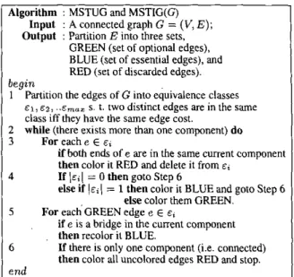
Since an MRMCST is an MST with the minimum radius among all possible MST's, this leads us to find the union graph of all MST's (called the MST Union Graph, MSTUG for short) and the intersection graph of all MST's (the MST Intersection Graph, MSTIG for short). We construct an MSTUG and an MSTIG by modifying the edge-coloring process introduced by Tarjan [26], in which edges are colored either blue (essential edges) or red (discarded edges). But neither blue nor red edges can be applied to the optional edges. By modifying the edge- coloring process, we introduce green edges to represent optional edges. The MSTUG contains all the blue and green edges while the MSTIG contains hlue edges only.
Initially there are n single components. As edges are colored green or blue, two components are merged together to produce one compo- nent. If there exists one and only one component, the algorithm will terminate after coloring all the uncolored edges red. The algorithm is summarized in Figure 3.
Aleorithm : MSTUG and MSTIG(G)
I Input : A connected graph G'=' (V, E ) ;
Output : Partition E into three sets, GREEN (set of optional edges), BLUE (set of essential edges), and RED (set of discarded edges). Partition the edges of G into equivalence classes
E I , E ~ , . . E ~ ~ ~ s. t. twodistinctedgesareinthesame
class iff thev have the same edee cost. begin
1
2 while (there exists more than &e component) do
3 For each e E E ;
if both ends of e are in the same current component then color it RED and delete it from E ,
If \ E , ( = 0 then goto Step 6
else if ( E , ( = 1 then color it BLUE and goto Step 6
4
else color them GREEN.
For eachGREEN edge e E E ,
if e is a bridge in the current component then recolor it BLUE.
If there is only one component (i.e. connected) then color all uncolored edges RED and stop. 5
6
end
Figure 3: Algorithm for consttucting an MSTUG and an MSTIG.
L13sr.d on t h n modified edgc-.mlonng proces, an MSrKti and nn \IS TIC; c m he ctmtructed in 01 U lg n) time. uhcrc ? I IS tne number
01 \cniccs Sre Figure J(b) for an rnamplc of MSTUG a d MSTIti cunmxmon.
After constructing an 41STI:G and an hISrIG. we may ohtmn se,.
cia1 hluc uses and optional edge5 unless ths MSr IS uniquc, m d then
mi \IK\ICST can he rtinrtruitsd hy rclsctmg uptional cdgcrr, to con- nect the blue tress We introduce a Pnm-haled heuristic. n a n d lorull) #>piu" t'nmirrtioii ,irarc'g? I LOCS,. fnr the MRMCST ciinstruction.
Thc I'nm-hnscd method conridcr, only one critenon If there 15 more thdn one miniindly cmt optiond edpe Incident 13 the hlue trec uith wurie .S. we hreak thc tic h) choosing the sdgc c = ( p . q ) , where p is
i n !he hluc irce uith wurce -i and ,I I S i n 3 neighboring blur trec T. t u
niininiiic J ( r , T ) dctincd hclou
J ( i , 7 ' , = d < ~ i ( . s . p ) T coal(c) .T- d t d ( c q , p c { 7 ' i j T c ; w ( p c ( l ' ) i ( 1 1
uhere O#zr,.~,y) I$ thc dirtancc from the source to the
n d r .
p , 3ndvo,t,t'J I\ lllc Icngth oicdge
Thc .MR\lCSI' algorithm lh3t r.nipluy> LOCS 15 ,uinmJrircd in Fig- ure 5 Sc? Figure 4 c ) ior the hlRMCST v i Figurr. 4th)
Theorem 1 The MRMCSTafgorithm runs in O(n+mOpt Ig m.,t) rime, where n is rhe number of vertices and mopt is the number of optional edges.
3.2 Crosstalk-Driven Layerfkack Assignment
As fabrication technology shrinks into the VDSM era, as pointed out in
[25],
on-chip minimum feature sizes continue to decrease, and devices and interconnection wires are placed in closer proximity in order to reduce interconnection delay and routing area. The increasing aspect ratio of wires and the decreasing of interconnect spacing have made the coupling capacitance larger than self capacitance. In fact, the ratio ofcoupling capacitance is reported to be even as high
as
70%-
80% ofthe total wiring capacitance, even in 0.25pm technology.
Crosstalk is mostly caused by coupling capacitance between inter- connection wires. In general, the crosstalk between two wires is pro- portional to their coupling capacitance, which is determined by the rel- ative positions of the wires. The coupling capacitance between
a
pair ofparallel wires is proportional to their coupling length, and is inversely proportional to their separating distance. The coupling capacitance be- tween a part of onhogonal wires is negligible in comparison with the coupling capacitance between a pair of parallel wires for current tech- nology. Consequently. it is reasonable to assume that there is crosstalk only between adjacent parallel wires.
: : :
. . .
. . . . . . .
.
.
.
.
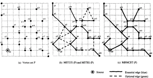
(a) vena l e t P ( b ) MSTUG (P) and MSTIG (P) ( c ) MRMCST(P)
Q
SDUrcCc-
Essential edge (blue)-
- -
Optional edge (green)Figure
4:
Example MRMCST construcuon. (a) The given verlex Set. (b) The MSTUG contains all edges while the MSTlG contlns all solid edges. (c) Theresulting MRMCST.
Recently, there has been much research on the coupling problem in both global and detailed routing. Zhou and Wong [27] minimized crosstalk at the global routing stage. Cbaudh;uy et al. 161 proposed wire soacinn after detailed routine. to reduce crosstalk. This technisue can be appliei as a post-processincand used for improving an existibg layout. but it is not suitable for routing.
However. both elobal routine. and detailed routine are not the best
The CLA problem
can
be formulated as the max-cut. k-coloring (MC) problem [241. However, the MC problem i s NP-complete P41. Thus, we resort to a simple yet efficient heuristic by constlucting a max- imum spanning tree from the given HCG. Since a tree can bek
colored in linear time if we have k layers, we shall first panition the vertices incident on edges with larger costs (coupling lengths) and allocates the corresponding segments to different layers.Let T be the set of tracks inside a panel. Each track t E T can be represented by its set of constituent contiguous intervals. Denoting these intervals by
xi,
we have t Eux;.
Eachxi
is eithera blocked interval, where no segment from
e
c m he assigned,an
occupied interval, where a segment frome
has been assigned a free interval, where no segment from the sete
has yet been01
assigned. To address these problems, Kay and Rutenbar [I71 suggested
an
in-teger linear programming (1LP)-based tracWlayer assignment method to do crosstalk optimization. However, the iLP-based approach is very time-consuming and thus not suitable for large and complex design. Bat- terywalaet al. 131 proposed a fast track assignment heuristic considering routahility, but crosstalk was not addressed in the work.
In this paper, we propose a fast layerltrack assignment heuristic for crosstalk optimization. After the coarsening stage, we may obtain some long horizontal and vertical segments. To simplify the layerltrack as- signment problem. we only assign segments which span more than one complete global cell in a row or a column. (We handle short segments during detailed routing.) The layerltrack assigner works
on
a full row orpone/
We first build the horizontal constraint graph
HCG(V,
E )
for all scgments in the panel. Each vertex t, t V corresponds to a segment in the panel. Two vertices U, and vj are connected byan
edge e E E iff these segmenrs h~long to two different nets and their spans Overlap. The cdge cost of e = vi) E E represents the coupling length if U; andU, are assigned IO adjacent tracks. We define the crosstalk-driven layer
assignment problem as follows:
a The Crosstalk-driven Layer Assignment (CLA) Problem: Given B set of layers L. a set of segmcnts
e,
and B cost functionr
: l! x L i N which represents the coupling cost of assigning a segment toa
layer, find an assignment that minimizes the sum ofthe coupling costs of each laycr.A segment seg E
e
is
said to he assignable t o t E T. t=
xi,
iffxi
n
seg#
g implies that either x i is a free interval or is an Interval occupied by a segment of the same net. Thus, the crosstalk-dnven track assignment problem can he defined as:0 The Crosstalk-driven
'hack
Assignment (CTA) Problem:Given a set of tracks T, a set of segments
e,
and a cost function0 :
e x
T
-+
N which represents the coupling cost of assigninga segment to a track,
find
an assignment that minimizes the sumof the coupling costs of the assignment.
After layer assignment, most of the edges with l%ger Costs in an
HCG
are eliminated, and the HCG is decomposed intok
subgraphs an exampleof
track assignment problem for a subHCG, wheree
= {a, b, e, d , e ,f}.
T
= { I , 2 , 3 , 4 ) . and obstacles On tracks are shadedin grey (e.g., the two obstacles on tracks
3
and 4). We use a bipartite assignment graph to indicate the assignability of segments to tracks. Forexample,
as
shown in Figure 6(h), edges between vertex a and vertices1.2, and 3 are introduced Since segment a can be assigned to track 1, 2, or 3, but not track 4. For easier implementation, we merge the subHCG and the bipartite assignment graph into a combination graph, as shown in Figure 6(c).
The CTA problem can he formulate as the Hamiltonian path problem which has been proven to be NP-complete
11 11.
We resort to a heuristic for the CTA problem. Our track assignment algorithm starts by finding the maximal sets of conflicting segments. This is equivalent to finding the largest clique V, in the subgraph subHCG;. Since the graph is an column of the global cell array at a time. Each row (column) is called a subHCGi, subHCGz,....
subHCGk if we have k layers. Figure 6 showsAlgorithm : MRMCST
Input : MSTUG, MSTIG and source 5
T,
= a blue tree containing the s;Output : An MRMCST begin 1 2 3 4 5 6 7 8 9 IO 11 12 13 14 15 16 17 18 19 20 21 22 23
Figure
5:
Algorithm for constructingan
MRMCSTinterval graph, finding the largest clique can he done in polynomial time. The algorithm first assigns one maximal subset
of
conflicting segments at a time by starting from the largest clique. Then we choose the longest segment in the clique as the sources
and assign it to the uppermost available track. Then, we choose the min-cost edge ( s , i ) (and thus the minimal coupling) and assign the segment associated with i to the first available track. If all tracks are occupied, we refer to the net associated with i as a failed net which will be reconsidered at the uncoarsening stage. We repeat the procedure by finding the min-cost edge ( i , j ) for further processing, where j is an unvisited vertex.Figure 7(a) shows the final track assignment for the instance of Fig- ure 6 . The maximum clique in the subHCG is
{ b ,
d , e,f),
and the longest segment in the clique is b. We thus assign segment b to the uppermost available track, which is track 1. See Figure 7(b) for the up- dated combination graph after assigningb
to track 1. Then, our heuristic makesb
the sourcefor
constructing the Hamiltonian pathfor
the clique. The min-cost edge e = ( b ,f)
incident on b is chosen, and f is assigned to the first available track. See Figure 7(c) for the updated combina- tion graph after assigningf
to
track 2. The process is repeated until all vertices in the clique are visited. We then have the track assignment solutiun shown in Figure 7(a).After the track assignment, the actual track position of a segment is known. Thus, we can perform point-to-segment maze routing to com- plete the routing.
4 Experimental Results
We have implemented our crosstalk-driven multilevel system in the C++ language on a 1 GHz SUN Blade 2000 workstation with IGB mem-
ory. We compared our results with [20] based on the six benchmark cir- cuits provided by the authors. See Table 1 for the benchmark circuits. (Note that the benchmark circuits used in 1201 also contain Mccl, Mcc2, S m c t , Prim1 and Prim2 However, as pointed out in [20I, those circuits do not have the information
of
net sources, and thus we cannot calcu-la1 (bl (Cl
Figure
6 :
Consuaint graph modeling for track assignment. (a) The subHCG Forthe given instance. (b) The corresponding bipartite assignment graph. (c) The:ombination graph.
I
(b) (C)
Figure
7 :
The process for track assignment. (a) The final back assignment for the instance of Figure 6 . (b) The resulting combination graph after assigning b tooack 1. (c) The resulting Combination graph after assigning f Io track 2.
late the delay For nets for those benchmarks. Therefore. we shall Focus our comparative studies on the six benchmark circuits listed in Table 1 .)
The design rules for wirelvia widths and wirelvia separation for detailed routing are the same as those used in (201.
Table 1 describes the set of benchmark circuits. In the table, "Sire" gives the layout dimensions, "#Layers" denotes the number of muting layers used, "#Nets" represents the number of two-pin connections after net decomposition. Since the resulls reported in (201 are better than
those in
[SI
and 171, we shall compare our multilevel router with that in (201.Experimental results on run-time, routing completion rate, delay, and crosstalk are listed in Tables 2 and 3, where "D,,," represenls the crit- ical path delay, "D,,," represents the average net delay,
"C,,,"
repre- sents the maximum coupling length of a net, and"C,,,"
represents the average coupling length. To perform experiments on timing-driven rout- ing, we used the same resistance and capacitance parameters as those usedin
(201 and set the constraint ratioh
used in (201 to 5.5 For compar- ison. (For this case, both routers have comparable routability, and thus it is easier to compare the delay and crosstalk results.) A via is modeled as the n-model circuit, with its resistance and capacitance being twiceof those of a wire segment. All the parameters were the same as those
S38417 I11430*6180 3
1
21035!
32210538684 112940G710
_ _
3 1 28177 42589-
I
35I
18I
sI
99796I
i n 6I
34I
r o w w
I
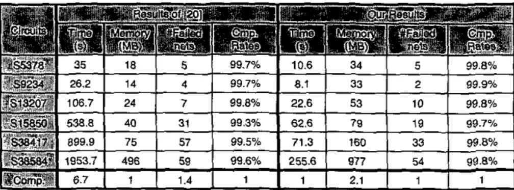
Table 2 : Results of run-time and routability comparison.
Table 3 : Results of timing and crosstalk comparison
used in
[ZO],
and both routers were run on the same machine. Com- pared with 1201, the experimental results show that our router achieveda 6.7X
iuntime speedup, reduced the respective maximum and average crosstalk (coupling lenglh) by about 30% and 24% reduced the respec- tive maximum and average delay by about 15% and 5%, and resulted in fewer failed nets.It should be noted that the coupling capacitance is not included in delay computation for fair comparison with
[ZO].
If coupling capaci- tance is considered, we can obtain even better timing reduction due to the significant crosstalk reduction.5 Conclusion
In t h s paper, we have proposed anovel framework for fast multilevel routing considering crosstalk and timing optimization. The experimen- tal results have shown that our algorithm is vely efficient and effective. Our future work lies in multilevel routing considering nanometer elec- trical effects.
References
II I C. AlbrechC "Globrl routing by new approximation algorithms for multicommdily
Raw: IEEE Tmnr. on CAD, vol. 20. no. 5, pp. 622-632. May 2 W I .
121 C. J. Alpen. J:R. Huang. and A. B. KaMg. "Multilevel circuit purtiiioning:' IEEE
Trans. on CAD, vol. 17. no. 8. pp. 6 5 5 4 6 7 . Aug. 1998.
14) T. F. Chan. J. Cong. T. Kong, I. U. Shinnerl. "Multilevel optimirvria for lzuge-rcrle
circuit placemenr."Pm. ICCAD, pp. 171-176, Nov. ZoW.
I51 Y:W. Chang. K. Zhu and D. F. Wong, "Timing-dnven muling for symmrmral-may-
bascd F S A E . " Trnnr on Dmlm Aulomnlron of Elecrmnrc Sy.mms, vol. 5. no. 3, pp.
433.450, July ZMX).
161 K.Chaudhury. AOnozawa, m d E . S . Kuh."Arpacingalgorillvoforperformanceand crarrtalk reduction
."
Pmc. ICCAD, pp. 197-702. Nov. 1993.171 I. Cong, J . Fang and Y Zhang. "Multilevel approach Io full-chip gridless routing: P m ICCAD. pp. 396-403. Nov. ZWI.
IS) J. Con& M. Xie and Y. U a n g . "An enhanced multilevel routing system: P r m IC- CAD, pp. 51 -58. Nov. 2WZ.
191 1. Cong, J. Fang and K. Khw. "DUNE A multi-layer gridless routing system with
wire plaming:'Pm. ISPD, pp. 12-18, Apr. 2oW.
I101 1. Cons. A. B. Kahng. G. Robins, M. Smafwdeb, and C. K. Wong. "Rovably g d
performance-driven global routing:' IEEE Trans. on CAD, vol 11. no 6, pp. 139.152, I"". 1992.
1111 7. H . Carmen. C. E. Lciserron. R. L. Rivcst, and C. Stcin, lnUOducBon Lo Algo-
rillvor," MITPrpsr. 2031
with wire-sizing and buffer-insertion for VLSl with multi-routing-layer: Pmc. ASP^ DAC.pp. 99-104.lan.2OW.
1131 M . Hayashi and S. Tnikiyama. "A hybrid hierarchical global router for multi-layer VLSSs," I N C E Tmnr. Fundnmmob. Vol. E78-A. No. 3. pp. 337-344 1995.
I141 D. high lo we^. "A solution 10 line routing problems on the continuour plane: Pmc. DAW, pp. 1-24, 1969.
11Sl G . KJrypiE. R. Aggarwal, V. Kumar. and S . sh&h%, "Mulukvevel hyprgsqh parU-
boning: Application in VLSl domun:' IEEE Trans. VLSI Sysremr. Vol. 7, pp. 69-79,
Mar. 1999.
I161 R. Kartna. E. Bozorgladch. and M. Smafradeh. "Pallem touting: use and theory for increasing predictability and avoiding coupling
."
IEEE Tmnr. on CAD, pp. 771.790, Nov. 2002.I121 T. Dcguchi, T. Koide and S. Wakabayarhi 'Yiming-dtivven hierarchical global routing
I181 Lee, "An a l g o r i m for paUl EomeCti~n and ifs applicadon? IRE Tmnr. El~rrnrnir
Computer, EC-In. 1961.
I191 S.~C. Lee. Y.-W. Chang. JLM. HI". and H. Yang. "Multilevel Irge-scale mdule flowplaminglplaccment using B*-treer:' Pmr. DAC.
w.
812-811, Jun. 2003. 120l S:P. Lin and Y:W. Chang. " A novel frsunework for multilevel routing consideringmutabilily and pedomnce:' Pmc. ICCAD. pp. 4450. Nov. ZWZ.
1211 Y:L. Lin. Y.-C. HI". m d R ~ S . Tsai."Hybtidrou~ng:'lEEET~~mni. on CAD, Vol. 9.
NO. 2.pp. 151-157. Feb. 1990.
1221 M. Marek-Sadowska. "Router planner for custom chip design:' Pmc. ICCAD. Nov. 1986.
1231 D. Y . Seo and D. T. L e . "On the complexity ofbicntcria spanning we problems for
a set of points in the plane," PhD disranniion in Nonhwrxiern unrvrrsiiy, 1999 1241 M.Sriram,S.Kang.J.D.Cho,andS.Ua)e,andM. S m a h a d e h " C r o s s r a l k . ~ ~ i m ~ ~
1251 D. Sylvester et al. "lnterconnecl scaling: Signal integrity and perlormaace in future
high-speed CMOS designi:'Pmc. VLSl Sympor,um on Technolozy, 1998. 1261 R. E. Tmjan. "Dau s t ~ ~ c t y r e o and network algorithms," CMBS 44. SIAM. 1983.
1271 H. Zhou and D . F. Wong, "Global routing wiul crosstalk constrainrs:'Pmc. DAC. pp. 374-317. Jun. 1998.