利用塊式高分子模板及具圖案奈米洞以溶液成長晶體法來成長二氧化鈦奈米針陣列
121
0
0
全文
(2) 利用塊式高分子模板及具圖案奈米洞以溶液成長晶體 法來成長二氧化鈦奈米針陣列 Using a solution crystal growth method to grow arrays of TiO2 nanoneedles in Block Copolymer Template and patterned nanocavities. 研 究 生:翁錦成. Student:Chin-Cheng Weng. 指 導 教 授:韋光華. Advisor:Kung-Hwa Wei. 國 立 交 通 大 學 材 料 科 學 與 工 程 系 博 士 論 文 A Thesis Submitted to Department of Materials Science and Engineering College of Engineering National Chiao Tung University in partial Fulfillment of the Requirements for the Degree of Doctor of Philosophy in Materials Science and Engineering Jun 2005 Hsinchu, Taiwan, Republic of China. 中華民國九十四年 六月.
(3) Abstract In the thesis, we report that using solution crystal growth method to grow TiO2 nanoneedles via blockcopolymer templates and nanocavities templates from E-beam lithography. The TiO2 nanoneedles crystal structure and properties have been studies in the thesis. In chapter 2, ordered aggregates of surfactant-modified TiO2 nanoparticles in the selective block of lamellar assemblies of the diblock copolymer PS-b-PMMA have been firstly prepared. The hydrophobic or hydrophilic nature of the tethered surfactant determines the location of TiO2 nanoparticles in the corresponding block, as confirmed by transmission electron microscopy, differential scanning calorimetry and Fourier-transform infrared spectroscopy.. The modes of dispersion of TiO2 in the blocks. depend on the type of bonding between the surfactant and TiO2 (covalent or ionic). Photoluminescence studies of these nanocomposites demonstrate that the location of TiO2 nanoparticles affect the block copolymer’s luminescence at different wavelengths. In chapter 3, we studies, arrayed, needle-like nanostructures of rutile phase crystal TiO2 were grown on a Si substrate containing TiO2 seeds prepared through a thin polystyrene-b-poly(4-vinylpyridine) (PS-b-P4VP) diblock copolymer template.. The. morphology of the deposited TiO2 nanostructures was characterized by field-emission scanning electron microscopy, X-ray diffraction and transmission electron microscopy (TEM).. By using TiO2 seeds prepared from their diblock copolymer PS-b-P4VP. template, arrayed, needle-like rutile TiO2 nanostructures with variable spatial positions and densities were fabricated.. The distance between two TiO2 needle bunches (120nm. and 160 nm) could be controlled using block copolymer templates with different molecular weights. Furthermore, in chapter 4, we report that single, aligned TiO2 nanoneedles having. i.
(4) diameters in the tens of nanometers can be grown through a solution crystal growth process from patterned nanocavities under the influence of an electric field.. The electric. field, which we applied perpendicular to the substrate plane, drove the precursor solution into the cavities by overcoming the surface tension encountered and oriented the TiO2 nanoneedles during the growth process. The effect of initial pH value of the precursor solution and urea concentration were studied and discussed.. We believe that this new. class of aligned TiO2 nanostructures will find a wide range of future applications... ii.
(5) 摘要 本論文主要利用塊式高分子及電子束微影法製作奈米模板,並以溶液成長晶體 法於奈米模板上成長二氧化鈦單晶態奈米針結構,進一步研究此奈米材料的結構鑑 定與特性分析。 第二章主要討論表面改質的二氧化鈦奈米顆粒可因其親水性之不同而分散於 PS-b-PMMA 塊式高分子中之任何一相,介面活性劑可利用共價鍵結方式與二氧化 鈦顆粒表面連結,此法可以使介面活性劑不會脫落而使得奈米顆粒分散於塊式高分 子中不至於產生聚集。 第三章討論以 Ti 離子模式加入 PS-b-P4VP 溶液中使之分散於 PVP 相中,在利 用旋轉塗佈使之形成單層膜結構,利用氧氣電漿將高分子膜移除後可形成二氧化鈦 的晶種陣列,最後再以此晶種以溶膠-凝膠法成長陣列結構的二氧化鈦奈米針,在使 用不同分子量的塊式高分子系統中可以發現,不同的分子量所做出的晶種間距不 同,因此可以利用此法來操控二氧化鈦奈米針陣列的密度。 第四章討論利用電子束微影的技術製作出不同尺寸大小的奈米洞,並以此奈米 洞來成長二氧化鈦,進一步的發現在適當的電場強度下可於 30-50 nm 尺寸大小的奈 米洞中成長出具有單晶態的直立且單根二氧化鈦奈米針,此外不同的起使酸鹼值及 尿素添加量亦改變二氧化鈦成長時的機制。 藉由本論文的研究將有助於瞭解以塊式高分子模板成長二氧化鈦奈米結構的機 制,此外單一根直立且具有單晶態的二氧化鈦奈米針亦可在適當的操控下成長出 來,此種新型態的材料將可用在太陽能電池等光電應用上。. iii.
(6) Acknowledgement 乙酉年夏至,天氣晴。 這本論文之所以能夠完成是要感謝非常非常多的人還有許多的樹木。 因緣際會的進入了這個實驗室,原本也沒有想到會待這麼久,在實驗室的七年 來經過了許多的風風雨雨,有許多的心酸、許多的歡笑,也有許多的收穫,這段時 間有許多的學長陪伴,教導、傳授,也有許多學弟妹的相伴、學習,這樣的過程回 想起來像是一場夢,一場夾雜著惡夢最終卻能讓你嘴角上揚的美夢。 回想那幾年我們的足跡曾踏遍了多少的領域開發了多少荒地,多少有趣的研究 創意是在那時候所激發出來,那個時候的我們就像是水庫裡的魚兒見到大洋,亦如 同白煙飄上天空才知自由的可貴,這樣的回憶是精采是豐富的。 一直以來,我總認為能夠與各位認識是我的榮幸,哈,說不定是有些人的不幸,論 文雖然只有一位指導教授,不過在生活上你們都是我的指導教授,這幾年我從一個 衝動且天不怕地不怕的小子慢慢的蛻變,這中間沒有你們的鼓勵與支持我相信我是 撐不住的,雖然還沒辦法將所有的感謝化作股票分送給各位,然而我誠摯的感謝是 無限的。 感謝韋光華老師多年來在研究上辛苦的指導,裘性天、趙桂蓉、陳登銘、吳春 桂等教授對於本論文的修正指教,田宏隆、何家充、田運宜、趙慶勳、江良祐、呂 奇明、蕭家傑、吳昭瑩、黃為國等學長姐的在實驗上生活上的指導與鼓勵,李振道、 林岱慶、洪金賢、蔣珮君、張世杰、蕭易男、邱麗娟、汪信亨、葉孝蔚、徐守謙、 巫真瑋、王彥博、李中斌、沈妙玲、鄭欽峰、周嘉宏、張耀德、陳琬琪、蕭淑敏、 黃清茂、林祐諄、周靜怡、謝孟婷、徐國峰、吳宗倫、謝慧玫、邱茂源、王旭生、 張含章、許碩麟、李世莉、陳振平、李紹睿等同學及學弟妹的相互扶持,三位博士 後研究員 Reddy, Kens 跟 Dina 實驗上的討論與幫助,還有熱心的助理朗克瑤小姐、 及超強 3M 蔡欣瑩小姐的幫忙,還有其他許多大學的同學及朋友的鼓勵幫助,此外家 人始終如一的扶持與愛護與女友馨儀的體諒與支持都是需要特別感謝的。 研究本身是一條不好走的路,像愛因斯坦說的:科學是永無止境的挑剔,然而這 不代表在巨山之前我們就要失去勇氣,俗話說的好:將相本無種,男兒當自強。此語 與學弟妹們一起共勉之。. iv.
(7) 札記 那年的夏天,宿舍外的樹幹上被畫了一條記號,也代表了新的開 始,我想知道之後記號會跑到他的哪個部位。因緣際會的考上了材料 所,圓了自己的夢想也安了爸媽的心,原本沒想到會讀到博士,然而 在實驗室的七年來經過了許多的風風雨雨,這樣的過程是許多人都曾 有過的而我也在其中,在那些趕實驗寫論文的日子,一起熬夜一起努 力的同學與學長,在每次快要凌晨的時候,總是互相鼓勵,而所有的 辛苦總在不知道不覺升上來的陽光中從我們的笑靨中淡化掉,我們都 相信儘管是在晨霧中盈弱的小草,也會有長大茁壯的一天,每一天我 們都抱著希望,愉悅地走過那枝芽翩翩的松林,期待那一天我們都會 像樹梢的鳥兒一樣,披上艷羽擺動雙翅翱翔在天空之中,然而研究的 過程多虧有耐心且不厭其煩的老師一而再再而三的不斷教導,讓我們 心裡面可以記得有教無類的孔子所說的一句話:學如不及猶恐失之, 要不然連我自己都不相信能夠畢業,然而在畢業之後,進入了社會大 學所需要學的是有別於學校課業上的東西,不過我相信不管會碰到怎 樣的困難只要在內心裡先存有了正確的態度,困難一定可以解決的。. v.
(8) Contents Abstract ·········································································································· i 中文摘要······························································································ ········ ii Acknowledgement················································································ ······· iv Content ································································································· ······· vi Lists of Table ························································································ ····· viii Lists of Figure ······················································································ ···· viiii Lists of Scheme ···················································································· ····· xiii Chapter 1. Introduction ····································································· ········ 1 1-1 Introduction ················································································ ········ 1 1-2 Template-based method for the preparation of nanomaterials···· ········ 2 1-3 Block Copolymers ······································································ ········ 8 1-4 Nanostructured Materials ··························································· ······ 17 1-5 Motivation and Scope Dissertation············································· ······ 23 1-6 References ·················································································· ······ 24. Chapter 2. Selective distribution of surface-modified TiO2 nanoparticles in polystyrene-b-poly (methyl methacrylate) diblock copolymer ·········································································· ······ 43 2-1 Introduction ················································································ ······ 43 2-2 Experimental section ·································································· ······ 45 2-3 Results and discussion ································································ ······ 47 2-4 Conclusions ················································································ ······ 51 2-5 References ·················································································· ······ 51 vi.
(9) Chapter 3. Synthesis of arrayed, TiO2 needle-like nanostructures via a polystyrene-block-poly(4-vinylpyridine) diblock copolymer template··········································································· ······ 66 3-1 Introduction ················································································ ······ 66 3-2 Experimental section ·································································· ······ 67 3-3 Results and discussion ································································ ······ 70 3-4 Conclusions ················································································ ······ 73 3-5 References ·················································································· ······ 74. Chapter 4. Using a solution crystal growth method to grow arrays of aligned, individually distinct, single-crystalline TiO2 nanoneedles within nanocavities ··································· ······ 86 4-1 Introduction ················································································ ······ 86 4-2 Experimental section ·································································· ······ 87 4-3 Results and discussion ································································ ······ 88 4-4 Conclusions ················································································ ······ 91 4-5 References ·················································································· ······ 92 Chapter 5 Conclusions ······································································· ·····104 Autobiography ..........................................................................................105. vii.
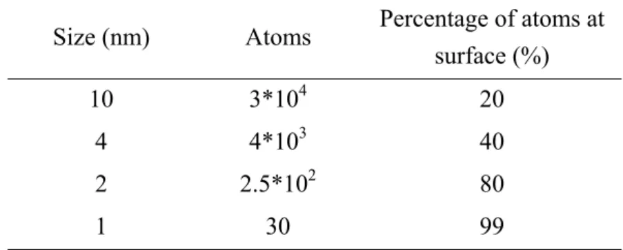
(10) List of Table Chap 1 Table 1-1. Relation between size and surface atoms ······················································· 32 Table 1-2. Confinement by the infinite Potential well ···················································· 32. Chap 2 Table 2-1. Compositions of TiO2 colloidal solutions ······················································ 54 Table 2-2. Onset of UV-vis absorbance and calculated radii of TiO2 nanoparticles ········ 55. Chap 3 Table 3-1. Reaction compositions of TiO2 nanostructures deposited from Ti precursor solutions for 1 and 6 hrs with ordered TiO2 seeds on the Si substrate············ 78. Chap 4 Table 4-1. The number of TiO2 nanoneedles within a single nanocavity ························ 95. viii.
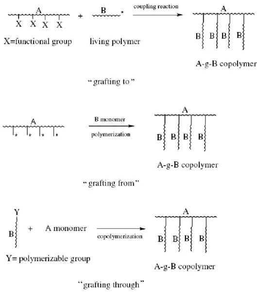
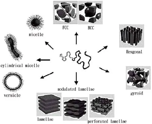
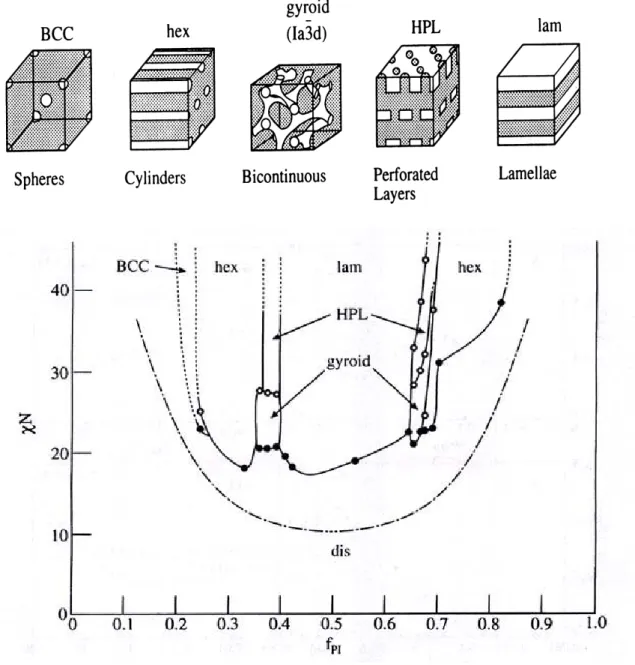
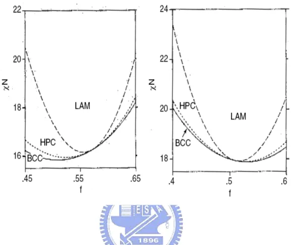
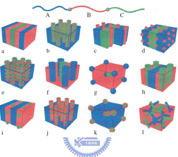
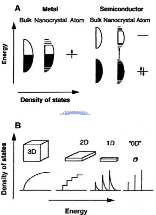
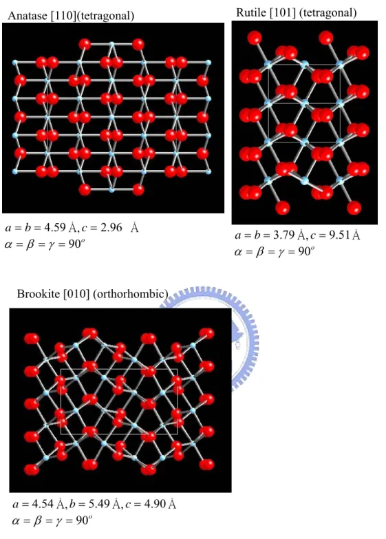
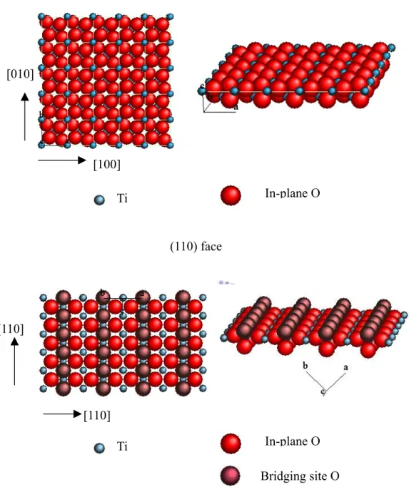
(11) List of Figure Chap 1 Figure 1-1. Some block copolymer architectures. ·························································· 33 Figure 1-2. Randomly branched graft copolymers can be prepared by three general synthetic methods: 1) the ‘‘grafting to’’, 2) the ‘‘grafting from’’, and 3) the ‘‘grafting through’’.···················································································· 34 Figure 1-3. Schematic representation of the different types of block copolymers: a) coil-coil diblock copolymers, b) rod-coil diblock copolymers (total molecular weight >20,000 g/mol), and c) rod-coil diblock oligomers (total molecular weight <20,000 g/mol).······························································ 35 Figure 1-4. The well-known structures of block copolymers in melt, solution or solid state. ··········································································································· 36 Figure 1-5. Experimentally determined phase diagram for PS-PI diblock copolymers··· 37 Figure 1-6. Phase diagrams for ABA triblock copolymer melts with τ=0.25 (left) and τ =0.5 (right). Solid lines give the disorder-to-order transition as (χNt) (f). Dotted lines give the transitions between bcc and hex, and dashed lines the transition from hex to lam. ········································································· 38 Figure 1-7. ABC linear triblock copolymer morphologies. Microdomains are colored following the code of the triblock molecule in the top. ····································· 39 Figure 1-8. A) Schematic illustration the density of state in metal and semiconductors. B) Variation of density of state of electrons with increase of the quantization dimension in quantum structure.································································· 40 Figure 1-9. The crystal structures of Anatase, Rutile and Brookite. Unit cells for each polymorph are shown by solid white lines.················································· 41 Figure 1-10. Schematic illustration of the atomic arrangements on ideal TiO2 (110) and (001) single crystal faces. ··········································································· 42. ix.
(12) Chap 2 Figure 2-1. UV-vis absorbance spectra of TiO2 colloidal solutions. ······························· 56 Figure 2-2. 29SiNMR spectrum of the TiO2-TMS colloidal solution.······························ 57 Figure 2-3.Transmission electron microscopy image and electron diffraction pattern of TiO2 nanoparticles from TiO2-H+ colloidal solution. ·································· 58 Figure 2-4. X-ray diffraction curve of TiO2-H+ nanoparticles.········································ 59 Figure 2-5. Transmission electron microscopy images of (a) PS-b-PMMA, (b) TiO2-TMAC/PS-b-PMMA and (c) shows an energy-dispersive x-ray diffraction pattern of the dark particles in (b), (d) TiO2-TMAC/PS-b-PMMA stained with RuO4.······················································································ 60 Figure 2-6. Differential scanning calorimetry curves of PS-b-PMMA, TiO2-TMS/PS-b-PMMA and TiO2-TMAC/PS-b-PMMA. ·························· 61 Figure 2-7. Fourier-transform infrared spectra of PS-b-PMMA and TiO2/PS-b-PMMA nanocomposites. ························································································· 62 Figure 2-8. Transmission electron microscopy image of TiO2-TMS/PS-b-PMMA. ······· 63 Figure 2-9. Schematic drawing of different dispersion modes by ionic-polar and covalent bondings between TiO2 and surfactants in PS-b-PMMA. ··························· 64 Figure 2-10. Photoluminescence of TiO2-TMS, PS-b-PMMA and TiO2/PS-b-PMMA nanocomposites. ························································································· 65. Chap 3 Figure 3-1. (a) Transmission electron microscopy image of SVP252 stained with RuO4 , (b) transmission electron microscopy image and (c) AFM topology in height images of a Ti(OH)22+/SVP252 (P=1) thin film. ········································· 79 Figure 3-2. (a) AFM topology and line-section analysis of ordered TiO2 seeds from a TiO2/SVP252 (P=1) thin film and (b) SEM image of TiO2 seeds from TiO2/SVP252 (after O2 plasma treating).···················································· 80 x.
(13) Figure 3-3. FE-SEM micrograph of TiO2 deposited on a Si wafer without TiO2 seeds in Ti precursor solution for (a) 1, (b) 6 and (c) 12 hrs.···································· 81 Figure 3-4. FE-SEM micrograph of TiO2 seeds from TiO2/SVP252 reacted in 0.0001M Ti precursor solution for (a) 1 hr (252L1) and (b) 6 hrs (252L6); and (c) a cross-sectional profile of a 252L6 TiO2 needle film; reacted in 0.0005M Ti precursor solution for (d) 1hr (252H1) and (e) 6 hrs (252H6); and (f) a cross-sectional profile of a 252H6 TiO2 needle film.·································· 82 Figure 3-5. FE-SEM micrograph of TiO2 seeds from TiO2/SVP229 reacted in 0.0005M Ti precursor solution for (a) 1 hr (229H1) and (b) 6 hrs(229H6); and (c) a cross-sectional profile of a 229H6 TiO2 needle film.·································· 83 Figure 3-6. X-ray diffraction curves of 252L6, 252H6 and 229H6 TiO2 needle-like nanostructures.···························································································· 84 Figure 3-7. (a) TEM image, (b) electron diffraction pattern and (c) HRTEM lattice image of the 252H6 TiO2 needle-like nanostructure.············································· 85. Chap 4 Figure 4-1. Wide-angle X-ray diffraction pattern of the TiO2 underlayer and powder. ··· 96 Figure 4-2. SEM images of a nano-patterned array of 50-nm cavities. (a) Plan view. (b) Cross-sectional image. ············································································· 97 Figure 4-3. SEM images (plan views, tilted 15°) of arrays of TiO2 nanoneedles grown from nanocavities sized at (a) 100, (b) 50, and (c) 30 nm.. The concentration. of the Ti precursor solution was 5 × 10⁻⁴ M, the ratio R was 200, the value of the initial pH was 1.0, and the applied electric field was 625 V/cm.. (d). Cross-sectional image of the TiO2 nanoneedles grown from the 30-nm-sized nanocavities.·································································································· 98 Figure 4-4. (a) An HRTEM image of a TiO2 nanoneedle.. xi. The spacing between adjacent.
(14) lattice planes is ca. 3.2 Å.. (b) An SAED pattern indicating that the TiO2. particle possesses a rutile crystal phase. ························································ 99 Figure 4-5. Wide-angle X-ray diffraction patterns of TiO2 nanoneedles obtained from aqueous solutions possessing different values of pHi. ································· 100 Figure 4-6. SEM images (plan views, tilted 15°) of arrays of TiO2 nanoneedles grown from nanocavities sized at (a) 100, (b) 50, and (c) 30 nm.. The concentration. of the Ti precursor solution was 5 × 10⁻⁴ M, the ratio R was 200, the value of the initial pH was 1.4, and the applied electric field was 625 V/cm.············ 101 Figure 4-7. SEM images of TiO2 nanoneedles grown when the ratio R was (a) 300, (b) 400, and (c) 500.. The concentration of the Ti precursor solution was 5 × 10⁻⁴. M, the value of the initial pH was 1.0, and the applied electric field was 625 V/cm.··········································································································· 102 Figure 4-8. (a) An HRTEM image of an anatase TiO2 needle. (b) The spacing between adjacent (002) lattice planes is ca. 4.7 Å as shown in the enlarged section. (c) An SAED pattern indicating that the TiO2 needle possesses an anatase crystal phase. ·········································································································· 103. xii.
(15) List of Scheme Chap 2 Scheme 2-1. Synthesis of TiO2 nanoparticles by ionic or non-ionic surfactants ······· 53. Chap 3 Scheme 3-1. Synthesis of needle-like TiO2 nanostructures with ordered patterns····· 77. Chap 4. Scheme 4-1. Graphical representations of (a) the synthesis of aligned single TiO2 nanoneedles and (b) the growth of nuclei within nanocavities·············· 94. xiii.
(16) Chapter 1 Introduction 1-1. Introduction. The English chemist John Dalton first proposed the scientific theory of the atom two hundred years ago (Summer, 1803).[1] Since then we have seen chemists come to understand the elements and their interactions, we have seen engineers make and use new materials to improve our lives, we have seen physicists demonstrate that even atoms are divisible, and we have seen warriors unleash the power of the atomic nucleus. In these two centuries we have amassed an enormous understanding of—and wielded an increasing control over—the fundamental units of matter.[2] On the evening of December 29, 1959, Feynman delivered an after-dinner lecture at the annual meeting of the American Physical Society; in that talk, called “There’s Plenty of Room at the Bottom,” Feynman proposed work in a field “in which little has been done, but in which an enormous amount can be done in principle.” “When we get to the very, very small world---say circuits of seven atoms---we have a lot of new things that would happen that represent completely new opportunities for design.” [3] This is the first time people talk and dream about “nano world”. As time going to twenty century, the field of nanostructure science and technology is a broad and interdisciplinary area of worldwide research and development activity that has been growing explosively in the past few years. While an understanding of the range and nature of functionalities that can be accessed through nanostructuring is just beginning to unfold, its tremendous potential for revolutionizing the ways in which materials and products are created is already clear. It is already having a significant commercial impact, and it will very certainly have a much greater impact in the future. [4] At 2000 year, US government pointed out the nanotechnology century is coming and. 1.
(17) writing a National nanotechnology initiative report (NNI), to lead the next industrial revolution.[5] In that reports, Neal Lane said : “If I were asked for an area of science and engineering that will most likely produce the breakthroughs of tomorrow, I would point to nanoscale science and engineering.” (–Neal Lane Assistant to the President For Science and Technology)[6] For years now, scientists have been developing synthetic nanostructures that could become the basis for countless improved and completely new technologies. Nanotechnology stands out as a likely launch pad to a new technological era because it focuses on perhaps the final engineering scales people have yet to master. Horst Stormer said : “Nanotechnology has given us the tools...to play with the ultimate toy box of nature—atoms and molecules. Everything is made from it...The possibilities to create new things appear limitless.” (–Horst Stormer , Lucent Technologies and Columbia University, Physics Nobel Prize Winner) and Roald Hoffmann said: “Nanotechnology is the way of ingeniously controlling the building of small and large structures, with intricate properties; it is the way of the future, a way of precise, controlled building, with incidentally, environmental benignness built in by design.” (–Roald Hoffmann, Cornell University, Chemistry Nobel Prize Winner).[6] Nanotechnology will take human a new vision of life and a new world of science. In the nanotechnology century, how to build nanostructure by bottom-up method is related to how to control the nano scale science. This is a new challenge for scientist and engineer.. 1-2. Template-based method for the preparation of nanomaterials. The fabrication of systems having characteristic dimensions smaller than 100 nm requires the ability to obtain and modify structures at the nanometer length scale. It is well established that microstructured materials may be industrially prepared, e.g., by photolithograph, but as the demand for smaller and smaller feature sizes, further steps. 2.
(18) towards miniaturization have been raised in the last decade, focusing on different and more suitable strategies, which are based on both “top-down” and ‘bottom-up” approaches. Many methods for the fabrication of nanomaterials have been developed, ranging from lithographic techniques to chemical methods.[7,8] This process involves synthesizing a desired material within the pores of a porous membrane. Because the membranes (templates) that are used have cylindrical pores or cavities of uniform diameter, a nanocylinder or a dot of the desired material is obtained in each pore. Depending on the properties of the material and the chemistry of the pore wall, this nanostructured materials may be solid (nanofibrils, nanorods, nanoparticles) or hollow (nanotube).. 1-2-1 Membranes used Most of the work in template synthesis, to date, has entailed the used of three types of nanoporous membranes, “track-etch” polymeric membranes, porous alumina membranes and block copolymer films. There are a variety of other templates that could be utilized. However, the main weakness of polymeric membranes and alumina membranes still remain in the difficult and poor control of the final morphology of the produced nanostructures. Recently, a sense polymers represent ideal nanoscale tools, not only due to their intrinsic dimensions, ease of synthesis and processing, strict control of architecture and chemical functionality, but also because of their peculiar mesophase separation both in bulk and in solution, particularly in the case of block copolymers (BCPs).. Furthermore, the BCPs monolayer films have been used to arrange the seeds,. which nanostructured materials could be fabricated via bottom-up approach.. 1-2-1-1 Track-etch Most of the nanoporous polymeric filtration membranes have been sold by a number of companies (such as Nucleopore and Poretics). This method entails bombarding a 3.
(19) non-porous sheet of the desired material with nuclear fission fragments to create damage tracks in the material, and then chemically etching these tracks into pores. These commercial membranes are prepared from polycarbonate or polyester. The resulting membranes contain randomly distributed cylindrical pores of uniform diameter which are available with pore diameter as small as 10 nm (pore density ca. 109 pores cm-2).[9]. 1-2-1-2 Porous alumina (anodic aluminum oxide, AAO) Porous alumina membranes are prepared via the anodization of aluminium metal in an acidic solution.[10] These membranes contain cylindrical pores of uniform diameter arranged in a hexagonal array. The pore diameter can be as large as 200 nm and as small as 5 nm, and the typical membrane thickness can range from 10 to 100 mm.[11] The higher pore density is important if one wanted to mass-produce a nanomaterial by the template method.[10]. 1-2-1-3 Block copolymers BCPs may be considered as two or more chemically homogeneous polymer fragments, i.e., homopolymer chains, joined to gather by covalent bonds to form more complex macromolecules such as linear di-, tri-, or mutiblock copolymer, and nonlinear architectures such as mutiarm, starblock, or graft copolymer. In the frequent case of immiscibility among the constituent polymers, the competing thermodynamic effects give rise to different kind of self-assembled morphologies, depending both in structure and dimensional terms on composition, segmental interaction, and molecular weight, and having periodicity suitable for application in nanotechnology.[12] The existence of some morphologies can be theoretically predicted within the self-consistent field theory,[13] on the basis of the volume fraction of the components, the number of segments in the copolymer, and the Flory-Huggins interaction parameter, as is the case for spherical, cylindrical, gyroid, amorphous diblock copolymers.. 4.
(20) A diblock copolymer chain consists of two chemically dissimilar blocks attached through a covalent bond can microphase separate into various ordered nanostructures with periodic thicknesses between 10 and 100 nanometers.[14] Thin films of diblock copolymers can therefore be used as lithographic templates to produce highly dense nanostructures[15-18], nanoreactors for the synthesis of nanocrystal clusters with spatial control or a template for the nanostructured materials growth.. 1-2-2 Template synthetic strategies The limits to which materials can be used in template synthesis are defined by the chemistry required to synthesize the material. Nearly any material can in principle be synthesized within pathway can be developed. Typical concerns that need to be addressed when developing new template synthetic methods include the following: (1) will the precursor solutions used to prepare the material ‘wet’ the pore (i.e., hydrophobic/hydrophilic considerations); (2) will the deposition reaction proceed too fast resulting in pore blockage at the membrane surface before tubule/fiber growth can occur within the pores; (3) will the host membrane be stable (i.e., thermally and chemically) with respect to the reaction conditions? The following is a general outline of five representative chemical strategies that have been used in our laboratory to conduct template synthesis within the alumina, polymeric membranes and block copolymers templates.. 1-2-2-1 Electrochemical deposition Electrochemical deposition of a material within the pores is accomplished by coating one face of the membrane with a metal film (usually via either ion sputtering or thermal evaporation) and using this metal film as a cathode for electroplating. [9,19-21] This method has been used to prepare a variety of metal nanowires including copper, platinum, gold, silver, nickel and metal oxide etc. in track-etch, alumina and block copolymer 5.
(21) templates. To obtain tubules, one must typically chemically derivative the pore walls so that the electrodeposited metal preferentially deposits on the pore wall; that is, a molecular anchor must be applied. For example, gold tubules have been prepared by attaching a cyanosilane to the walls of the alumina template membrane prior to metal or semiconducting materials depositions.[9,19] Owing to the large number of commercially available silanes, this method can provide a general route for tailoring the pore walls in the alumina membranes.. 1-2-2-2 Electroless deposition Electroless metal deposition involves the use of a chemical reducing agent to plate a metal from solution onto a surface.[22] This method differs from electrochemical deposition in that the surface to be coated need not be electronically conductive. One of these methods is involving a sensitizer to bind to the surface via complexation with surface amine, carbonyl, and hydroxyl group. This sensitized membrane is then activated by exposure to Ag+ resulting in the formation of discrete nanoscopic Ag particles on the membrane’s surface. Finally, the Ag-coated is immersed into an Au plating bath containing AuI and a reducing agent, which results in Au plating on the membrane faces and pore walls. The key feature of the electroless deposition process is that metal deposition in the pores starts at the pore wall. Therefore, after short deposition times, a hollow metal tubule is obtained within each pore while long deposition times result in solid metal nanowires. Unlike the electrochemical deposition method where the length of the metal nanowires can be controlled at will, electroless deposition yield structures that run the complete thickness of the template membrane.. 1-2-2-3 Chemical polymerization Chemical template synthesis of a polymer can be accomplished by simply immersing the membrane into a solution containing the desired monomer and a polymerization 6.
(22) reagent. This process has been used to synthesize a variety of conductive polymers within the pores of various template membranes.[ 23-24] As with electrochemical polymerization, the polymer preferentially nucleates and grows on the pore walls, resulting in tubules at short deposition times and fibers at long times.. 1-2-2-4 Sol-gel Deposition Sol-gel chemistry typically involves hydrolysis of a solution of a precursor molecule to obtain first a suspension of colloidal particles (the sol) and then a gel composed of aggregated sol particles. The gel is then thermally treated to yield the desired product. A variety of inorganic semiconducting materials including TiO2, ZnO, and WO3 have been explored. [25-27] First, an alumina template membrane is immersed into a sol for a given period of time, and the sol deposits on the pore walls. After thermal treatment, either a tubule or fibril of the desired semiconductor is formed within the pore. The formation of tubules after short immersion times indicates that the sol particles absorb to the alumina membrane’s pore wall. This is expected because the pore walls are negatively charged while the sol particles used to date are positively charged.. 1-2-2-5 Chemical vapor deposition A major hurdle in applying chemical vapor deposition (CVD) techniques to template synthesis has been that deposition rates are often too fast. As a result, the surface of the pores becomes blocked before the chemical vapor can traverse the length of the pore. Two template-based CVD syntheses circumvent this problem. The first entails the CVD of carbon within porous alumina membranes which has been achieved.[28] This involves placing an alumina membrane in a high-temperature furnace and passing a gas such as ethane or propane through the membrane. Thermal decomposition of the gas occurs throughout the pores, resulting in the deposition of carbon films along the length of the pore wall. The second CVD technique utilizes a template-synthesized structure as a 7.
(23) substrate for CVD deposition. [29] For example, a CVD method was used to coat an ensemble of gold nanotubules with concentric TiS2 outer nanotubules.. 1-3. Block Copolymers. 1-2-1 Introduction Since the discovery of the living character of anionic polymerization in the mid-1950s (Szwarc 1956)[30], about 50,000 references have been published on block copolymer synthesis, properties, and applications through the end of 2000 (Sci Finder 2000). A total of 42% of these papers have appeared in the last few years (1995 through 2000).[31] Over the last few years, tremendous research efforts have been dedicated to the study of potential applications of block copolymers in advanced technologies, such as information storage, drug delivery, photonic crystals, etc.[32-36] These studies have shown that block copolymers are very strong candidates for applications in these areas. Conventional and potential high-technology applications of block copolymers are based on their ability to self-assemble, in bulk or in selective solvents, into ordered nanostructures, with dimensions comparable to chain dimensions. By changing the molecular weight, chemical structure, molecular architecture, and composition of block copolymers, the size scale, the type of ordering, and the characteristics of these nanostructures can be manipulated. The nanoscale self-organization of polymers can be achieved simply by joining polymer chains together in a block copolymer. With these remarkable materials, the molecular engineer can combine distinct polymers to give materials with defined physical properties. For example, a composite comprising glassy or crystalline domains in a rubbery matrix can be self-assembled by taking components with these characteristics and combining them in a block copolymer. Because the polymer chains are tethered to each other, macroscopic phase separation cannot occur and structural organization occurs 8.
(24) in domains with periodicities ~1-100nm, whether in the melt, solid, thin film or in micellar solution.. The nanoscale self-organization phenomenon is very useful for. nanotechnology applications.. 1-3-2 Architecture of copolymer The architectures of copolymer can be controlled by the synthesis procedure, and it is possible to prepare diblock, triblock, mutiblock, startblock and graft copolymers.. These. are illustrated in Fig 1-1. Examples of other exotic architectures have recently been synthesized. The possibilities for molecular design seem to be almost limitless, only being limited by the chemist’s imagination. Chemically joining two homopolymers to form a diblock copolymer increases the compatibility, and this is reflected in the reduction of the critical temperature for phase separation as compared to a homopolymer blend. Linear AB block copolymers are the simplest block copolymer structures where two blocks of different chemical structures are linked together through a common junction point. A variety of triblock copolymer architectures, i.e., block copolymers containing three sequences of monomers, are possible because they can be comprised of two (ABA copolymers) or three (ABC terpolymers) different monomers. Each type of triblock can be synthesized according to an appropriate synthetic pathway depending on the monomers used and their sequence in the triblock chain. The triblock copolymer phase diagrams below are highly asymmetric. The reason for this asymmetry is the high deformation of the central B blocks in order to accommodate the outer A blocks into A domains. Increasing τ gives rise to important differences in the window of stability for each morphology at a given composition. Star block copolymers are actually star-shaped macromolecules where each arm is a block copolymer. The number of branches can vary from a few to several tens. The. 9.
(25) topological difference of this kind of macromolecules, with respect to linear block copolymers, is focused on the existence of a central branching point, which, by itself, brings certain symmetry in the macromolecule and sometimes defines a certain amount of intramolecular ordering. Graft copolymers are comprised of a main polymer chain, the backbone, having one or more side polymer chains attached to it through covalent bonds, the branches. The chemical nature and composition of the backbone and the branches differ in most cases. Branches are usually distributed randomly along the backbone although, recently, advances in synthetic methods allowed the preparation of more well-defined structures. Randomly branched graft copolymers can be prepared by three general synthetic methods: 1) the ‘‘grafting to’’, 2) the ‘‘grafting from’’, and 3) the ‘‘grafting through’’ or macromonomer method.[37-38]. The detail scheme was shown in Fig 1-2.. By designing these building blocks in such a way that they contain all the necessary information to direct their self-assembly into functional materials.. Whereas it is. difficult to organize low molecular weight organic molecules into periodic macroscopic assemblies, macromolecules can be assembled into a large variety of ordered morphologies covering several length-scales.. Three different classes of block. copolymer type building blocks have been developed (Fig. 1-3).. First, the coil-coil type. diblock copolymers form the building blocks of self-assembled materials.. The other. two classes of diblock copolymer architectures are composed of a rigid rod-segment and a flexible coilblock, which are divided between low molecular weight and high molecular weight rod-coil block copolymers. Coil-coil diblock copolymers, i.e., block copolymers comprised of two flexible, chemically incompatible and dissimilar blocks (e.g., poly(styrene)-b-poly(isoprene)) can microphase separate into a variety of morphologies. An example of the self-assembling systems is provided by rod-coil molecules that have a strong tendency to self-organize into a variety of supramolecular structures in nanoscale 10.
(26) dimensions.[39-44] For a given molecular rod, the relative lengths of the coil segments determine the resulting rod domain structures that include infinitely long cylinders and disk-like cylinders. These domains subsequently self-organize into 2-D hexagonal and 3-D bodycentered tetragonal symmetries, respectively.. 1-3-3 Synthesis of block copolymers The methods to synthesize block copolymer are anionic polymerization, cation polymerization, and living free radical polymerization. Anionic living polymerization has been known for almost fifty years. Since its discovery in the 1950s, it has emerged as the most powerful synthetic tool for the preparation of well-defined polymers, i.e., narrow molecular weight distribution polymers with controlled molecular characteristics including molecular weight, composition, microstructure, and architecture. Its ability to form well-defined macromolecules is mainly due to the absence of termination and chain transfer reactions, under appropriate conditions [45-46]. Advances in cationic polymerization methodology, starting in the middle 80s with the discovery of the true living cationic polymerization of vinyl ethers by Higashimura et al. [47-48], have shown their real potential for the synthesis of tailor-made macromolecules. In recent years many investigations have demonstrated that almost all classes of cationically polymerizable vinyl and alkene-type monomers can be polymerized in a controllable way [49-51]. The formation of polymers having predictable molecular weight and narrow molecular weight distributions gives unambiguous experimental evidence for elimination or suppression of termination and chain transfer reactions in these systems. These studies opened the way for block copolymer synthesis using cationically polymerizable monomers, extending the range of block copolymers available. 11.
數據

+7
相關文件
溶液中離子沈澱反應的化學反應式表示法:以氯化鈉和硝酸銀的反應為例(如上圖)
在慢速乾燥填補了 ZnO 奈米柱和 Polymer 的間距,因為延長了乾燥 時間,溼膜有很長時間有效滲入 ZnO
包括具有藥理活性的高分子和低分子藥物高分子化或
SPO has high fatty acids, therefor it has to carry out the acid catalyzed esterification to convert of the fatty acids in SPO to biodiesel first, and then used the
(1)針對具有中子研究專長者,具備下列要件之 一:①物理、化學、核工系所博士畢業,具 二年以上中子研究經驗;執行中子散射、繞
The prepared nanostructured titania were applied for the photoanodes of dye-sensitized solar cell.. The photoanodes were prepared by the doctor blade technique and the area
威遠炮臺是第一次鴉片戰爭的古戰場,也是虎門海口防務的主要陣地。炮臺平 面呈月牙形,全長 360 米,高 6.2 米,寬 7.6
威遠炮臺是第一次鴉片戰爭的古戰場,也是虎門海口防務的主要陣 地。炮臺平面呈月牙形,全長 360 米,高 6.2 米,寬 7.6
