2254 IEEE PHOTONICS TECHNOLOGY LETTERS, VOL. 16, NO. 10, OCTOBER 2004
Multimode Optical Demultiplexer for DWDM With
Liquid Crystal Enabled Functionalities
Ming-Jay Huang, Ru-Pin Pan, Chia-Rong Sheu, Yu-Ping Lan, Yi-Fan Lai, and Ci-Ling Pan, Senior Member, IEEE
Abstract—We have developed a liquid-crystal-based multimode optical demultiplexer (DEMUX) with additional functionali-ties such as switching and power equalization. Demultiplexing 16-channel 100-GHz-spaced signals into a 62.5- m multi-mode-fiber array is demonstrated. The central wavelength of each channel is designed according to the International Telecom-munication Union grid. Adjacent channel crosstalk is less than 30 dB. The average 1- and 3-dB passbands of the DEMUX are 12.5 and 22.5 GHz, respectively. A maximum extinction ratio of 16.2 dB is achieved. Different channels can be switched with rise and fall times of 10 and 70 ms, respectively. The outputs of the channels are equalized to 65 dBm. The variation between different channels reduced from 10 dB to less than 0.5 dB.
Index Terms—Demultiplexer (DEMUX), dense wavelength-divi-sion multiplexing (DWDM), equalizer, liquid crystal (LC), spatial light modulator (SLM), switching.
I. INTRODUCTION
D
ENSE wavelength-division-multiplexing (DWDM) tech-nology is an effective way to increase the transmission bandwidth of optical communication systems. It requires high-performance multiplexers and demultiplexers (DEMUXs) with low insertion loss (IL), wide channel passband, low crosstalk, and low polarization dependence loss. A number of different designs of DEMUXs have been implemented in the past, using gratings [1], thin film structures [2], fiber Bragg grat-ings [3], and arrayed waveguide gratgrat-ings [4], etc. On the other hand, liquid crystal (LC) devices have long been developed for wavelength-division multiplexing. Previously, a six-port DEMUX using an LC etalon was fabricated [5]. LC polariza-tion rotators and Wollaston beam deflectors were employed in a symmetric grating-based system to construct 1 2 switches that can switch independently eight wavelength channels 4 nm apart [6]. 100-GHz-resolution dynamic channel management was accomplished by using in-line LC spatial light modulator (SLM) and a grating together in the collimated beam of aManuscript received January 19, 2004; revised June 5, 2004. This work was supported in part by grants from the National Science Council and Ministry of Education of the Republic of China, as well as the Lee-MTI Foundation.
M.-J. Huang and Y.-P. Lan were with the Institute of Electro-Optical Engi-neering and Department of Electrophysics, National Chiao Tung University, Hsinchu 300, Taiwan, R.O.C. They are now with the Center for Measurement Standards, Industrial Technology Research Institute, Hsinchu 300, Taiwan, R.O.C. (e-mail: [email protected]).
R.-P. Pan, Y.-F. Lai, and C.-L. Pan are with the Institute of Electro-Optical Engineering and Department of Electrophysics, National Chiao Tung Univer-sity, Hsinchu 300, Taiwan, R.O.C.
C.-R. Sheu was with the Institute of Electro-Optical Engineering and Depart-ment of Electrophysics, National Chiao Tung University, Hsinchu 300, Taiwan, R.O.C. He is now with the Electronic Research and Service Organization, In-dustrial Technology Research Institute, Hsinchu 310, Taiwan, R.O.C.
Digital Object Identifier 10.1109/LPT.2004.834584
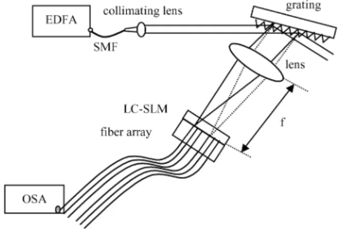
Fig. 1. Experimental setup. SMF: Single-mode fiber.f : Focal length.
4-f relay optic system between input and output single-mode fibers [7]. For DWDM applications in metropolitan area net-works and local area netnet-works, multimode DEMUXs are attractive. A compact athermalized low-loss eight-channel 200-GHz grating-based multimode DEMUX with low IL and low thermal effect has recently been reported [8]. In this letter, we present a new liquid-crystal-based multimode DEMUX or LC-multi-DEMUX. It differs from the previous design in two aspects: 1) the LC-SLM is placed at the focal plane of the folded telescopic grating system; 2) every other pixel of the LC-SLM was matched to one multimode fiber channel. This design is derived from our previously work on electrically con-trolled tunable external cavity semiconductor lasers and filters using LC-SLM technology [9]–[11]. A 16-channel 100-GHz DEMUX with channel switching or routing function as well as power equalization is demonstrated.
II. DEVICECONSTRUCTION ANDOPERATIONPRINCIPLES
A schematic drawing of the construction and testing of the LC-multi-DEMUX is shown in Fig. 1. The broad-band output of an erbium-doped fiber amplifier (EDFA) is collimated and di-rected onto a diffraction grating (1100 lines/mm) at an incident angle of 84 . The first-order-diffracted light from the grating is collected by a lens, focused on to the LC-SLM and cou-pled into a 16-channel array of multimode optical fibers. The LC-SLM is basically a twisted nematic LC (NLC) cell oper-ated in the normally black mode. The cell is constructed with an 8- m-thick NLC (E7, Merck) layer sandwiched between in-dium–tin–oxide (ITO)-coated glass plates. One of the ITO elec-trodes is patterned. The pattern consists of 96 100 m 2.4 cm stripes with 25- m spacing (see Fig. 2). The LC-SLM is driven with a sinusoidal voltage at 1 kHz. The maximum contrast or
HUANG et al.: MULTIMODE OPTICAL DEMUX FOR DWDM WITH LC ENABLED FUNCTIONALITIES 2255
Fig. 2 (a) Structure of the fiber array. (b) Arrangement of the LC-SLM with respect to the fiber array. Gray areas are the pixels of the LC-SLM. Concentric circles indicate positions of the multimode fibers.
extinction ratio andON-state transmission of the LC-SLM are 16.2 dB and 90%, respectively. The amplitude of the threshold switching voltage of the LC-SLM is 1 V at 1 kHz. Complete switching fromOFF- toON-state is achieved beyond 4.2 V. The
driving voltage of the LC-SLM is 10 V in this work.
The relation between the separation of the central wave-lengths (or frequency) of the channels (or ), and the center-to-center separation of the corresponding pixels of the LC-SLM is given by
or
(1) where is the grating period, is the angle of first-order dif-fracted beam with respect to the grating normal , and is the focal length of lens ( mm). The device is designed to have 16 output channels and central wavelength according to the International Telecommunication Union (ITU) grid. The channel spacing is 100 GHz. The channels can be opened or blocked by switchingON orOFFthe corresponding pixels. The variable optical attenuation mode of the LC-multi-DEMUX is simply accomplished by tuning the driving voltage applied to the strips of pixels of the LC-SLM.
The configuration of the 16-channel multimode fiber array is shown in Fig. 2(a). The core diameter of each fiber is 62.5 m and the pitch is 250 m. The pixel pitch and width of the LC-SLM are 125 and 100 m, respectively. Thus, the core of each fiber is cocentered with every other pixel of the LC-SLM. The arrangement of the fiber array with respect to the pixels of the LC-SLM is shown in Fig. 2(b). For monitoring the output of the LC-multi-DEMUX, we employ an optical spectrum analyzer [(OSA) Advantest Q8384, resolution 0.01 nm].
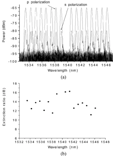
Fig. 3. (a) Power-equalized output of the 16 channels of the LC-DEMUX. (b) Extinction ratios of the individual channels versus wavelengths (p-polarized).
III. RESULTS ANDDISCUSSIONS
The output spectra of the 16-channel LC-multi-DEMUX for both s- and p-polarizations are shown in Fig. 3(a). The present device is polarization sensitive with a polarization dependent loss of about 15 dB. It can be improved by using a polarization-insensitive grating [8] and polarization inde-pendent polymer-dispersed LC for the LC-SLM. The output wavelengths of the channels are in good agreement with the theoretical prediction according to (1) and the ITU wavelengths (within 0.04 nm or 5 GHz). The crosstalk of adjacent chan-nels is less than 30 dB. The average 1- and 3-dB passbands of the DEMUX are 12.5 and 22.5 GHz, respectively. The IL for the LC-multi-DEMUX prototype is approximately 12 dB, which includes 3-dB loss of the unpolarized light from the EDFA. The losses incurred on signal light propagating through the collimating lens, grating, lens, and LC-SLM are 0.7, 1.5, 1, and 3 dB, respectively. The remaining loss is attributed to that of coupling into the fiber array. We expect the best achievable IL for the LC-multi-DEMUX to be about 5 dB.
As the pixels can be individually switchedON–OFFand the transmission of the particular channel adjusted, the LC-multi-DEMUX has additional functionalities as compared to conven-tional DEMUXs. The outputs of the channels are equalized to 65 dBm. The variation between different channels is reduced
2256 IEEE PHOTONICS TECHNOLOGY LETTERS, VOL. 16, NO. 10, OCTOBER 2004
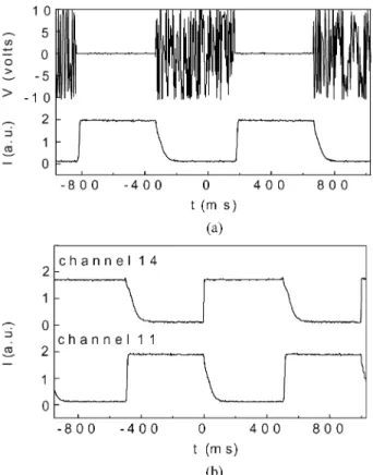
Fig. 4. (a) Switching characteristics of a single channel of the LC-DEMUX. Upper trace: Driving voltage waveform (the 1-kHz signal is chopped at 1 Hz). Lower trace: Output of the LC-DEMUX. (b) Output of two channels of the LC-DEMUX by switching the Channels 11 and 14ONandOFFby turns.
from 10 dB to less than 0.5 dB. The pixel-ON–OFF character-istics of the 16 channels of the LC-multi-DEMUX are shown in Fig. 3(b). The extinction ratios for pixelsON–OFFfor the 16 channels range from 11.1 to 16.2 dB. The average extinction ratio is 12.6 dB. We have employed polarization optics with extinction ratios of . The extinction ratio of the LC-multi-DEMUX is theoretically better than 30 dB, but depends criti-cally on the thickness of the LC layer [12]. Thus, the extinc-tion ratios of different channels of our home-made LC-multi-DEMUX fluctuate because the thickness of the LC-SLM is not uniform across the channels.
The switching characteristic of a single channel of the LC-multi-DEMUX is shown in Fig. 4(a). The upper trace is the 1-kHz driving waveform (inverted to that actually applied) across the LC-multi-DEMUX pixel. The lower one is the LC-multi-DEMUX output intensity. The rise (10% to 90% of the total intensity excursion) and fall (90% to 10% when the voltage is turned OFF) times measured are typically 10 and 70 ms, respectively. Results for switching between two channels are shown in Fig. 4(b). The upper waveform shows the state of the 14th channel ( nm) and the lower waveform is the state of the 11th channel ( nm). When the 14th channel is in ON-state, the 11th channel is in
OFF-state, and vice versa.
The design concept of the present device can be extended readily to other grating-based DEMUXs, which employ either echelle gratings or array waveguide grating as the dispersion elements.
IV. CONCLUSION
We have designed and demonstrated a LC-based 16-channel DEMUX with 100-GHz channel spacing. The center wave-lengths of the channels are designed and operated according to the ITU grid. The crosstalk between channels is less than 30 dB. The average 1- and 3-dB passbands of the DEMUX are 12.5 and 22.5 GHz, respectively. The average extinction ratios of the channels are 12.6 dB. This approach enables additional functionalities of the DEMUX, such as dynamic gain equaliza-tion. The outputs of the channels of the LC-multi-DEMUX are equalized to 65 dBm, with variation less than 0.5 dB. Further, different channels can be switched ON and OFF as desired,
with rise and fall times of 10 and 70 ms, respectively. The concept of the present device can be readily extended to other types of grating based DEMUXs.
REFERENCES
[1] F. Zhao, J. Qiao, X. Deng, J. Zou, B. Guo, and R. Collins, “Reliable grating-based wavelength division (de)multiplexers for otptical net-works,” Opt. Eng., vol. 40, pp. 1204–1211, 2001.
[2] K. Sano, R. Watanabe, and J. Minowa, “A 4-wavelength optical multi/demultiplexer for WDM subscriber loop systems using analog baseband video transimmission,” J. Lightwave Technol., vol. LT-4, pp. 631–639, June 1986.
[3] R. H. Qu, H. Zhao, Z. J. Fang, E. Marin, and J. P. Meunier, “Config-urable wavelength-selective switch based on fiber grating and fiber loop mirror,” IEEE Photon. Technol. Lett., vol. 12, pp. 1343–1345, Oct. 2000. [4] K. Takada, M. Abe, M. Shibata, M. Ishii, and K. Okamoto, “Low-crosstalk 10-GHz-spaced 512-channel array-waveguide grating multi/demultiplexer fabricated on a 4-in wafer,” IEEE Photon. Technol.
Lett., vol. 13, pp. 1182–1184, Nov. 2001.
[5] K. Hirabayashi and T. Kurokawa, “Tunable wavelength-selective demul-tiplexer using a liquid-crystal filter,” IEEE Photon. Technol. Lett., vol. 4, pp. 737–740, July 1992.
[6] J. S. Patel and Y. Silberberg, “Liquid crystal and grating-based multiple-wavelength cross-connect switch,” IEEE Photon. Technol. Lett., vol. 7, pp. 514–516, May 1995.
[7] A. D. Cohen, M. C. Parker, and R. J. Mears, “100-GHz-Resolution dynamic holographic channel management for WDM,” IEEE Photon.
Technol. Lett., vol. 11, pp. 851–853, July 1999.
[8] J. Qiao, F. Zhao, R. T. Chen, J. W. Horwitz, and W. W. Morey, “Ather-malized low-loss echelle-grating-based multimode dense wavelength di-vision demultiplwxer,” Appl. Opt., vol. 41, no. 31, pp. 6567–6575, 2002. [9] R.-P. Pan, X.-X. Tung, J.-Y. Chen, M.-J. Huang, and C.-L. Pan, “Liquid-crystal-based tunable optical filtering devices for DWDM,” in
Proc. SPIE, Active, and Passive Optical Components WDM Communi-cation, vol. 4532, 2001, pp. 244–248.
[10] C. L. Pan, S.-H. Tsai, R.-P. Pan, C.-R. Sheu, and S. C. Wang, “Tunable semiconductor laser with liquid crystal pixel mirror in grating-loaded external cavity,” Electron. Lett., vol. 35, pp. 1472–1473, 1999. [11] R.-P. Pan, H.-C. Tung, C.-R. Sheu, M.-J. Huang, and C.-L. Pan,
“Wave-length tunable semiconductor laser with a liquid crystal pixel mirror,” in Proc. SPIE, Liquid Crystal Materials, Devices VIII Applications, vol. 4658, 2002, pp. 91–100.
[12] P. Yeh and C. Gu, Optics of Liquid Crystal Displays. New York: Wiley, 1999, p. 124.