on decreasing for the higher order modes (Q factor 23.65 at 1.44 GHz). Dominant mode resonance is used as high Q cavity. Q can be further increased by using substrate of highr.
4. CONCLUSIONS
In this submission, a new approach towards computation of input impedance of a probe-fed ring resonator is presented. This method, unlike other cavity models, can be generalized to predict accu-rately the resonant resistance of first few modes of such resonator with reasonable accuracy. A high degree of agreement is observed between present model and MOM based analysis. Needless to point out that such models are intuitive, fast to compute and does not demand high computation power.
REFERENCES
1. P.A. Bernard and J.M. Gautray, Measurement of dielectric constant using microstrip ring resonator, IEEE Trans Microwave Theory Tech 9 (1991), 592–595.
2. P. Troughton, Measurement techniques in microstrip, Electron Lett 5 (1969), 25–26.
3. C. Edwards, Microstrip measurements, IEEE MTT-S Int Microwave Symp Dig, Boston, MA, (1982), 338 –341.
4. I.M. Stephenson and B. Easter, Resonant techniques for establishing the equivalent circuits of small discontinuities in microstrip. Electron Lett 7 (1971), 582–584.
5. A.K. Bhattacharyya and R. Garg, Input impedance of annular ring microstrip antenna using circuit theory approach, IEEE Trans Anten-nas Propag Ap-33 (1985), 369 –374.
6. P. Pirinoli, G. Vecchi and M. Orefiee, Full wave spectral analysis and design of annular antenna with electromagnetically coupled microstrip feed line, IEEE Trans Antenna Propag 52 (2004), 2415–2423. 7. J.S. Row, Design of aperture coupled annular ring microstrip antennas
for circular polarization, IEEE Trans Antenna Propag 53 (2005), 1779 –1784.
8. R.E. Collin and F.J. Zucker, Antenna theory Part-I, McGraw-Hill, New York, 1969.
9. A. De, Studies on rectangular and circular patch radiators, Ph.D thesis, Indian Institute of Technology Kharagpur, 1984.
10. Kai Chang, Lung-Hwa Hsieh, Microwave ring circuits and related structures Wiley-Interscience, USA, 2004.
11. T. Chakravarty, S. Biswas, A. Majumdhar and A. De, Computation of resonant frequency of annular ring loaded circular patch using cavity model analysis, Microwave Opt Technol Letts 48 (2006), 622– 626.
12. S. Yano and A Ishimaru, A theoretical study of the input impedance of a circular microstrip disk antenna, IEEE Trans Antennas Propag AP-29 (1981), 77– 83.
13. J.X. Zheng, D.C. Chang, End-correction network of a coaxial probe for microstrip patch antennas, IEEE Trans Antennas Propag AP-39 (1991), 115–118.
© 2007 Wiley Periodicals, Inc.
A NOVEL DESIGN OF A
MICROSTRIP-FED SHORTED SQUARE-RING SLOT
ANTENNA FOR CIRCULAR
POLARIZATION
Kow-Ming Chang,1Ren-Jie Lin,1I-Chung Deng,2and
Qing-Xiang Ke2
1Department of Electronics Engineering and Institute of Electronics,
National Chiao Tung University, Hsinchu, Taiwan 30050, Republic of China
2Department of Electronics Engineering and Institute of Mechatronic
Engineering, Technology and Science Institute of Northern Taiwan, Taipei, Taiwan 112, Republic of China
Received 12 December 2006
ABSTRACT: The design of a circularly polarized slot antenna fed by a
single microstrip line is presented. The circularly polarized radiation is achieved by means of using a shorted square-ring slot. This pro-posed antenna has the fundamental resonant frequency of 2.4 GHz
with the minimum return loss of⫺50.44 dB. The impedance
band-width is 930 MHz or 38.7% referred to the resonant frequency, and it also has the 3-dB axial-ratio (AR) bandwidth of 310 MHz or 12.9% referred to the resonant frequency. In addition, this proposed antenna shows good performance of circular polarization (CP) radi-ation with the range of the lower 3-dB AR value covering elevradi-ation
angles between⫺40 to 40 degrees. © 2007 Wiley Periodicals, Inc.
Microwave Opt Technol Lett 49: 1684 –1687, 2007; Published online in Wiley InterScience (www.interscience.wiley.com). DOI 10.1002/mop. 22517
Key words: circular polarization; slot antenna; microstrip line; axial
ratio
1. INTRODUCTION
Printed ring slot antennas have several advantages such as low profile, light weight, easy to manufacture and wide impedance bandwidth. Slot antennas also have wider circular polarization bandwidth than that of microstrip antennas. Previous report [1] shows the possibility to obtain CP radiation by using a shorted strip at an appropriate position along the ring slot. This shorted strip is applied to a cavity-backed annular slot antenna, and the antenna uses a coaxial probe feed to produce CP radiation. Several microstrip-fed ring-slot antennas producing CP radiation are proposed [2– 4]. Chen et al. [2] employs the concept of [1] to achieve the 3-dB axial-ratio (AR) bandwidth of 8.4% and 8.1% for annual and square ring-slot antennas, respectively. However, the frequency at which the mini-mum AR value occurs does not meet the fundamental resonant frequency. In comparison with [2], the ring-slot antennas without shorted strip have the 3-dB AR bandwidths of only about 3.5% and 4.3% for annular and square ring-slot, respectively. In addition, the 2⫻ 2 ring-slot antenna array with a 3-dB AR bandwidth of 15% is presented in [4], but the frequency of the minimum AR value is not the same as the fundamental resonant frequency.
In this article, we propose a novel design of CP slot antenna to separate the two geometric factors of controlling the fundamental Figure 6 Variation of resonant resistance with frequency (r⫽ 2.2, r0⫽
35 mm h⫽ 1.59 mm)
resonant frequency and the frequency of the minimum AR value. In our proposed antenna, a shorted strip has an included angle of 45° relative to the microstrip feedline, and this method is different from these previous studies [1– 4].
2. ANTENNA CONFIGURATIONS
The configuration of the proposed microstrip-fed circularly-polar-ized square-ring slot antenna is depicted in Figure 1. The substrate used an inexpensive FR4 dielectric substrate with a thickness of 1.6 mm, a relative permittivity of 4.4, and a loss tangent of 0.0245. The dimensions of this proposed antenna are listed in Table I. The ground plane of the proposed antenna has a length of L1 and a width of W1. The shorted square-ring slot has outer and inner side lengths of L2 and L3, respectively, and the shorted strip has an included angle of 45° with respect to the microstrip feedline. If the shorted strip is located at the lower left corner, the slot antenna excited a right-hand circular polarization (RHCP) radiation in the upper half free space. Similarly, the left-hand circular polarization (LHCP) radiation observed in the upper half free space can be achieved by locating the shorted strip at the lower right corner. Also note that, for the proposed antenna, the free space wavelength at the operating frequency at which the minimum AR occurs is
about the mean circumference of the ring slot. A 50 Ohm input microstrip feedline with a width of Wfis connected to an imped-ance transformer with a width of W7. To reduce the antenna size TABLE 1 The Dimensions of the Proposed Antenna
L1 L2 L3 L4 L5 L6 L7 c1 c2 c3
(mm) 64 40 25 20 11.5 2 2.75 2 2 4
W1 W2 W3 W4 W5 W6 W7 Wf g1
(mm) 60 40 25 20 3 3.5 1 3 1.4
Figure 1 Configuration of the proposed microstrip-fed circularly polar-ized slot antenna
Figure 2 Simulated and measured results of return loss against fre-quency for the proposed antenna
Figure 3 Simulated polarization patterns at the frequency of 2.4 GHz for the proposed antenna
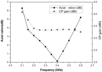
Figure 4 Simulated results of axial-ratio and CP gain against frequency for the proposed antenna
and match the 50⍀ microstrip feedline (Wf⫽ 3 mm), the meander impedance transformer and three tuning stubs are conducted. The three stubs only affect the return-loss value and the fundamental
resonant frequency, but have less influence on the AR operating frequency. In addition, a square slot with a length of L4 is located at the center of the slot antenna. This square slot is able to make the AR operating frequency to meet the fundamental resonant frequency. Further, the three small triangles (with widths of c1, c2, and c3) located at the corners of the shorted ring slot are capable of making the radiation patterns of CP more symmetric along the elevation angle of 0°. In the proposed antenna, the most important geometric factor in the return loss response is the meander trans-former and the three tuning stubs. Besides, the mean square-ring slot circumference is the main geometric factor impacting on the AR response. The two geometric factors separately control their individual antenna response and less influence on each other. This is convenient for the antenna design.
3. RESULTS AND DISCUSSIONS
Figure 2 demonstrates the simulated and measured results of return loss against frequency for the proposed antenna. The measured result shows that the antenna has a fundamental resonant fre-quency of 2.4 GHz with the minimum return loss of⫺50.44 dB and the impedance bandwidth of 930 MHz (or 38.7%) covering the frequency range from 1.83 GHz to 2.76 GHz. The free space wavelength of 2.4 GHz is about 125 mm and approximately equals the mean circumference of square-ring slot (about 130 mm). The simulated polarization patterns are shown in Figure 3. The pro-posed antenna radiates right hand circular polarization (RHCP) in the upper half free space and left hand circular polarization (LHCP) in the lower half free space. Besides, the simulated results of axial ratio and CP gain against frequency for the proposed antenna are shown in Figure 4. It is shown that the 3-dB AR bandwidth is 310 MHz or 12.9%, including the frequencies range from 2.21 GHz to 2.52 GHz, and the 1-dB AR bandwidth is about 100 MHz. The minimum AR value of about 0.1 dB is located at the frequency of 2.4 GHz. Besides, the CP gains are about 3.3 dBi and almost keep constant during 3-dB AR bandwidth. The measure-ment of polarization patterns in this study employs the rotating source method [5]. The measured results of polarization patterns at different frequencies of 2.3, 2.4, and 2.5 GHz are shown in Figure 5. These ripples in the polarization patterns are a consequence of the beam ellipticity, which occurs when a finite cross-polar com-ponent exists. The depth of the ripples defines the AR value. They present well circular polarization and also obtain good axial-ratio
Figure 5 Measured polarization patterns at different frequencies of 2.3, 2.4 and 2.5 GHz for the proposed antenna. [Color figure can be viewed in the online issue, which is available at www.interscience.wiley.com]
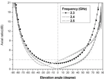
Figure 6 Axial ratio against elevation angle calculated from the mea-sured polarization patterns
values over a wide angle range. From Figure 5, the elevation-angle ranges with respected to lower 3-dB AR are⫺33 to 29, ⫺43 to 47 and⫺49 to 9°, respectively, for 2.3, 2.4 and 2.5 GHz in the upper half free space. It can be seen that the space distribution of the AR value are more symmetric at the frequencies of 2.3 and 2.4 GHz than that at the frequency of 2.5 GHz. To further manifest the symmetric distribution of axial ratio, the calculated results ob-tained from the depth of the ripples in these measured polarization patterns are shown in Figure 6. It can be observed that the AR pattern with respect to elevation angle is nearly symmetric along the elevation angle of 0° at the frequencies of 2.3 and 2.4 GHz. By using the three small triangles at the square-ring slot corners to perturb the magnetic current within the square-ring slot, the sym-metric AR space distribution and the minimum AR position can be further controlled. In this proposed antenna, the length of c3 (4 mm) is not equal to the length of c1 and c2 (2 mm), and in this condition, a very symmetric AR space distribution can be
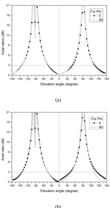
achieved. To manifest this phenomenon, the simulated results of axial ratio against elevation angle for the proposed antenna with and without three small triangles at the frequency of 2.4 GHz are shown in Figures 7(a) and 7(b) respectively. It can be observed that the AR distribution in the elevation direction for the proposed antenna with three small triangles is more symmetric along the elevation angle of 0° than that without three triangles.
4. CONCLUSIONS
A microstrip-fed CP square shorted ring-slot antenna has been investigated and successfully implemented. The return loss char-acteristic and CP radiation performance can be controlled and improved individually. The proposed antenna has several advan-tages at the same time which include return loss of⫺50.44 dB at the resonant frequency of 2.4 GHz, impedance bandwidth of 930 MHz, 3-dB AR bandwidth of 310 MHz, and good broadside CP radiation patterns over a wide elevation angle range of 80° in the azimuthal directions. The proposed antenna presents excellent performances and is very suitable for wireless communication applications
ACKNOWLEDGMENT
This project is supported by National Science Council under grant NSC 94 –3111-466 – 003-Y21.
REFERENCES
1. H. Morishita, K. Hirasawa, and K. Fujimoto, Analysis of a cavity backed annular slot antenna with one point shorted, IEEE Trans An-tennas Propag 39 (1991), 1472–1478.
2. W.S. Chen, C.C. Huang, and K.L. Wong, Microstrip-line-fed printed shorted ring-slot antenna for circular polarization, Microwave Opt Technol Lett 3 (2001), 137–140.
3. K.L. Wong, C.C. Huang, and W.S. Chen, Printed ring slot antenna for circular polarization, IEEE Trans Antennas Propag 50 (2002), 75–77. 4. J.S. Row, C.Y.D. Sim, and K.W. Lin, Broadband printed ring-slot array
with circular polarization, Electron Lett 41 (2005), 110 –112. 5. B.Y. Toh, R. Cahill, and Vincent F, Fusco, Understanding and
measur-ing circular polarization, IEEE Trans Edu 46 (2003), 313–318.
© 2007 Wiley Periodicals, Inc.
BUILDING A RESONANT CAVITY FOR
THE MEASUREMENT OF MICROWAVE
DIELECTRIC PERMITTIVITY OF HIGH
LOSS MATERIALS
C. P. L. Rubinger and L. C. Costa
Physics Department, University of Aveiro, 3810 –193 Aveiro, Portugal
Received 19 December 2006
ABSTRACT: The design of a cavity resonator implies to solve the
Maxwell equations inside that cavity, respecting the boundary condi-tions. As a consequence, the resonance frequencies appear as conditions in the solutions of the differential equation involved. The measurement
of the complex permittivity,* ⫽ ⬘-i⬙, can be made using the small
perturbation theory. In this method, the resonance frequency and the quality factor of the cavity, with and without a sample, can be used to calculate the complex dielectric permittivity of the material. We measure
the shift in the resonant frequency of the cavity,⌬f, caused by the
inser-tion of the sample inside the cavity, which can be related to the real
part of the complex permittivity,⬘ , and the change in the inverse of
the quality factor of the cavity,⌬(1/Q) , which can be related with the
imaginary part,⬙. This is valid for very small perturbations of the
elec-Figure 7 Simulated axial ratio against elevation angle at the frequency of 2.4 GHz for the proposed antenna (a) with and (b) without three small triangles