國 立 交 通 大 學
電機與控制工程學系
碩 士 論 文
利用 PTZ 攝影機實現動態背景中
特定物體之鎖定追蹤技術
Real Time Tracking System for Specific Moving
Object under Dynamic Background Using
Modified Mean-Shift Algorithm
研 究 生:林訓緯
指導教授:林進燈 博士
利用 PTZ 攝影機實現動態背景中特定物體之
鎖定追蹤技術
Real Time Tracking System for Specific Moving
Object under Dynamic Background Using
Modified Mean-Shift Algorithm
研 究 生:林訓緯 Student:Hsun-Wei Li
指導教授:林進燈 博士
Advisor:Dr. Chin-Teng Lin
國立交通大學
電機與控制工程學系
碩士論文
A Thesis
Submitted to Department of Electrical and Control Engineering
College of Engineering and Computer Science
National Chiao Tung University
in Partial Fulfillment of the Requirements
for the Degree of Master
in
Electrical and Control Engineering
June 2006
Hsinchu, Taiwan, Republic of China
利用 PTZ 攝影機實現動態背景中特定物體之
鎖定追蹤技術
學生:林訓緯
指導教授:林進燈 博士
國立交通大學電機與控制工程研究所
Chinese Abstract摘 要
本論文針對移動中的物體,提出一套基於改良後的Mean-Shift 演算法,實現 在主動式攝影機上的影像即時追蹤系統。在我們的系統架構下,可以區分成三個 部分。第一個部分是以影像為基礎之動態物體偵測模組;第二個部分是將所偵測 到的動態物體,進行鎖定以及連續平滑的追蹤;第三個部份則是針對主動式攝影 機所開發的控制模組。首先,我們會記錄下所偵測到的動態物體,利用其色彩資 訊,使用我們所改良後的Mean-Shift 演算法,配合上主動式攝影機的控制,進行 鎖定且不間斷的追蹤。因此,本論文所提出之技術不但可追蹤鎖定移動中的物 體,使之保持在攝影機可視範圍的中間;並且在鎖定目標物的過程當中,若此目 標物的尺寸小於我們所設定臨界值的時候,系統會自動調整攝影機焦距的倍率, 以便得到清晰可辨識的影像,大幅提升追蹤的品質。Real Time Tracking System for Specific Moving
Object under Dynamic Background Using
Modified Mean-Shift Algorithm
Student: Hsun-Wei Lin
Advisor: Dr. Chin-Teng Lin
Department of Electrical and Control Engineering
National Chiao Tung University
English Abstract
Abstract
This thesis presents a study of a smooth tracking system for non-rigidity moving object using modified mean-shift algorithm implemented on an active pan-tilt-zoom camera. In our approach, the system is divided into three parts: moving object detection module, modified mean-shift tracking module including position tracking and size selecting algorithm, and an automatic pan-tilt-zoom camera control system. We detect the moving object by frame difference method plus some image processing techniques, such as erosion, dilation and image projection, and use HSV color space to reduce the illumination affection. We also develop a modified mean-shift algorithm by choosing a specific kernel function. Moreover we adopt a different position tracking and size selecting method for smooth tracking and locking target.
Chinese Acknowledgements
致 謝
本論文的完成,首先要感謝指導教授林進燈博士這兩年來的細心指導,讓我 學習到許多寶貴的知識,在學業及研究方法上也受益良多。另外也要感謝口試委 員們的建議與指教,使得本論文更為完整。 其次,感謝資訊媒體實驗室的學長蒲鶴章博士以及學長劉得正博士的指導, 剛維學長、Linda 學姊、家昇學長、庭瑋學長的大力相助,肇廷同學、亞書同學、 育弘同學、立倬同學的幫忙以及我的大學好友蘇品翰、莊詠峻、劉建興、黃世豪、 何振綱、楊奐箴、藍善凡、古傑天、張家銘的相互砥礪,還有實驗室裡所有的學 長、同學和學弟們在研究過程及生活上所給予的協助及鼓勵,讓我在這兩年的研 究生涯,無論是課業上、學業上或是生活上都不孤單。 最後,我更是要感謝我的父母,他們從小到大對我的教育以及栽培,並給予 我精神和物質上的一切支援,讓我能安心地致力於學業,如果沒有他們無怨無悔 的付出,就不會有現在的我。 謹以本論文獻給我的家人及所有關心我的師長與朋友們。Contents
Chinese Abstract ...ii
English Abstract ... iii
Chinese Acknowledgements ...iv
Contents ...v
List of Figures...vii
Chapter 1 Introduction...1
1.1 Motivation...2
1.2 Literal Survey...3
1.2.1 Motion Estimation Method...4
1.2.2 Mean-Shift Tracking Method...5
1.2.3 Adaptive size tracking Method ...6
1.3 Contribution ...7
1.4 Thesis Organization ...7
Chapter 2 System Overview...8
2.1 System Architecture...10
2.1.1 Video Sequence Analysis...10
2.1.2 Camera Control...12
2.2 Hardware Platform...14
Chapter 3 Deformable Dynamic Tracking System ...16
3.1 Moving Object Detection...16
3.2 HSV Color Transformation...20
3.3 Mean-Shift Tracking ...23
3.3.1 Mean-Shift Tracking Theorem...23
3.3.2 Mean-Shift Tracking Algorithm...24
3.4 Adaptive Size Selecting ...26
Chapter 4 PTZ Control System ...31
4.1 Basic Mechanism...32
4.2 Pan and Tilt Control...34
4.3 Zoom control...36
5.2 Environment Setup...40
5.3 Tracking Region Experiment ...43
5.4 Color Space Experiment ...47
5.5 Fix Size Tracking Experiment ...49
5.6 Adaptive Size Tracking Experiment ...52
Chapter 6 Conclusions and Future Works ...53
6.1 Conclusions...53
6.2 Future Works...54
List of Figures
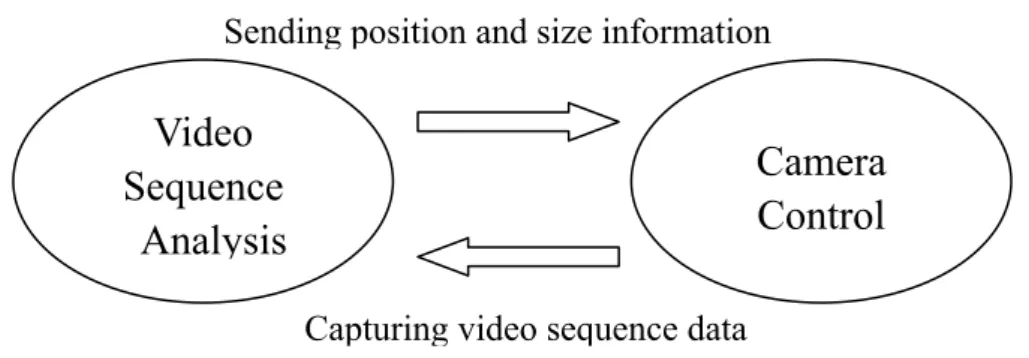
Figure 2-1 : Relationship between video sequence analysis and camera control ...9
Figure 2-2 : Whole system Overview ...9
Figure 2-3 : The flow chart of video sequence analysis ...10
Figure 2-4 : The flow chart of motion detection...11
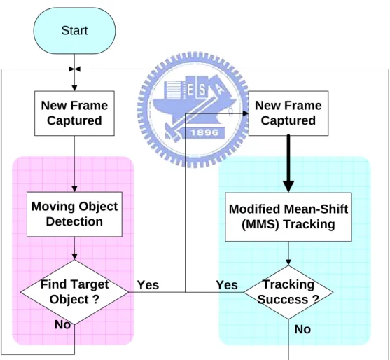
Figure 2-5 : The flow chart of mean-shift tracking system ...12
Figure 2-6 : Divide screen into 9 regions...13
Figure 2-7 : 8 control directions for each region ...13
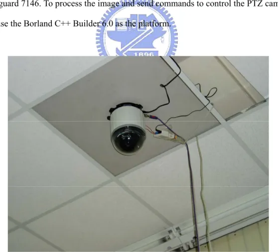
Figure 2-8 : Lilin PIH-7600 High Speed PTZ Dome ...14
Figure 2-9 : Hardware platform diagram ...15
Figure 3-1 : (a) previous frame (left) (b) current frame (right)...17
Figure 3-2 : The result of frame difference in Figure 3-1...17
Figure 3-3 : Difference map after erosion and dilation...18
Figure 3-4 : Image projection ...19
Figure 3-5 : The rectangle region and the elliptic region...19
Figure 3-6 : RGB color model [28]...21
Figure 3-7 : HSV color model [29]...21
Figure 3-8 : Three different size candidates...26
Figure 3-9 : Tracking region is chosen by hand...28
Figure 3-10 : The tracking result after 4 times iteration. ...29
Figure 4-1 : Command Description ...32
Figure 4-2 : Pan/Tilt Speed Control...32
Figure 4-3 : Divide monitor screen into 9 difference regions...33
Figure 4-4 : Pan and tilt control (position control) ...34
Figure 4-5 : Control command format ...35
Figure 4-6 : The target size is too large...36
Figure 4-7 : The target size is too small...36
Figure 4-8 : The Command Format of Zoom in/out ...37
Figure 4-9 : The flow chart of zoom control...37
Figure 5-1 : Experimental environment I...40
Figure 5-2 : Experimental environment II ...41
Figure 5-3 : Experimental environment III...41
Figure 5-4 : Zoom condition I...41
Figure 5-5 : Zoom condition II ...42
Figure 5-6 : Zoom condition III...42
Figure 5-9 : Tracking result using ecliptic region...45
Figure 5-10 : Coordinate definitions and three different tracking regions ...46
Figure 5-11 : Iteration time comparison (unit: times)...46
Figure 5-12 : Tracking with RGB color model...47
Figure 5-13 : Tracking with RGB and HSV color model at frame 391 and 412 ...48
Figure 5-14 : Fix size tracking result (sequence 1)...49
Figure 5-15 : Fix size tracking result (sequence 2)...50
Figure 5-16 : Fix size tracking result (sequence 3)...51
1
Chapter 1
Introduction
Detection and tracking of moving object under dynamic background are becoming more and more important tasks in the computer vision 、 robots self-recognition and visual-based surveillance system. Visual-based surveillance system has been generally applied in many different fields with strong demands of security such as banks, department stores, parking lots…etc. There are two types of cameras used in video surveillance system: fixed cameras and active cameras. The background fixes for the former but varies for the latter.
Although the view angle for active camera at some coordinate is limited, it can still monitor at the surveillance environment by panning, tilting and zooming the position of itself. Although both fixed cameras and active cameras have already been implemented into commercial equipments, they just transmit the video sequence which are displayed on some remote monitor and might be stored in hard disks or optical devices. No further analysis of the video content proceeds. What would improve the surveillance system more reliable or more intelligent? Modern digital image processing technology and control engineering makes it possible. The surveillance system will become more efficient, effective and humanistic when an active camera can track the moving object or invading persons in the dynamic background and perform the function of zooming in and out precisely. An active camera can move up-down direction (tilt) and left-right direction (pan), and has the ability to perform zooming in and out automatically. Tracking with the active camera
panning and tilting can keep the target in the scene whenever the target is going to move away from the monitoring region and can also zoom in or zoom out when the target is too close or too far away from the camera. Moreover, in such dynamic background, the object may be non-rigidity, rotation and partial occlusion. In this thesis, we develop a visual surveillance system of deformable moving object tracking under dynamic background by integrating the algorithms of real time moving object detection, real time mean-shift tracking including adaptive size searching for moving object, and automatically zooming on an active pan-tilt-zoom camera.
1.1 Motivation
Most automatic tracking systems for visual surveillance implemented on active fix-zoom cameras usually have just two degrees of freedom, pan and tilt. In [1], there is an automatic tracking method that uses motion vector detection for active surveillance system. They try to find to global motion vector to compensate between two sequential and dynamic frames. And then use the frame difference subtraction to find the moving object from the dynamic background. But the limit of them is the tilt angel can not be too large to lead to failing of motion vector detection. When the tilt angel is larger than some degrees, the motion vector will become rotational, and that will cause the dynamic tracking based on motion vector detection not working anymore. In [2], they try to find the different parts of the two sequential video frames, and control an active camera to track them. But this method can not handle dynamic background. There are many existing tracking system handle the pan-tilt control of an active camera [3 4 and 5], but they usually use the difference frame or background subtraction and also can not reach the dynamic background tracking demand.
dynamic background tracking because the mean-shift method is based on color histogram tracking. So no matter how the background would change abnormally, this method can lock the target object and will not get influenced by the changing of the background. However, the tracking will be lost when fixed size is used in the mean-shift tracking method due to the variant distance from moving object to camera.
Besides, because the mean-shift method is sensitive to the change of the color histogram, the variation of illumination of moving object in surveillance environment causes the tracking failure. When the illumination of the surveillance is changed, the color histogram of the target will be different even if it is not moving or disappearing at all.
Those above reasons above motivates us to develop a moving object tracking system under the dynamic background surveillance using an active pan-tilt-zoom camera, so it can track and zoom the target object. In moving object detection we use the frame difference method plus some digital image processing techniques to extract the moving object. In moving object tracking, we use the mean-shift tracking method which is based on normalized color histogram of HSV color space to avoid the variation in illumination of moving object.
1.2 Literal Survey
In this section, we will introduce some popular methods for moving object detection and tracking, such as motion estimation and mean-shift tracking. There are some pros and cons of these methods and we will point them out and find better ways to satisfy our demands.
1.2.1 Motion Estimation Method
The most common motion estimation method is the full search block matching motion estimation method [7]. When the block searching range or the global motion vector is too large, the computational loading will be too heavy to perform the real-time dynamic tracking. Some substitutional methods, such as Cross Search (CS) [8], Diamond Search (DS) [9], Hexagon-Based Search (HEXBS) [10]…etc, are proposed to reduce the computational power of global motion estimation, and some of them are really useful.
The most efficient method we have ever used for the real-time global motion vector estimation is the specific point motion estimation method [11] which is used in digital image stabilization system. This method actually can calculate the global motion vector in real-time performance, and we can use it to compensate the global motion vector between two sequential frames so that will be easy to fulfill the dynamic tracking intention. But when this kind of dynamic tracking method comes to the PTZ camera, it fails to calculate the global motion vector because the global motion vector is not just vertical and horizontal. In other words, the global motion vector will become rotational so the estimation method will be ineffectual.
When the active PTZ camera tilts at some angles, panning the camera will let the global motion vector become rotational. Handling the rotational global motion vector will be difficult to meet the real-time dynamic tracking demand. So we choose the mean-shift method to track the non-rigidity, rotational and partial occlusion targets.
1.2.2 Mean-Shift Tracking Method
A real-time detection system for color image sequence is present by G. L. Foresti [12]. The approach is used in video-based surveillance system for monitoring indoor scene. Another moving object tracking system using the background registration technique is present by Shao-Ti Chien [13]. Both methods introduced above give us a nice performance on moving object tracking, but they can not track on the specific target continuously if there is non-rigidity, rotational and partial occlusion.
The mean-shift algorithm has often been used in the areas of clustering [14] [15], detection and tracking [16] by virtue of its low cost and simplicity in computation. The mean-shift tracking method is a nonparametric statistical method for seeking the target candidate that is the most similar to the given model distribution [17].The algorithm has recently been adopted as an efficient technique for tracking [18] because of the mean-shift method only concerns the color histogram distribution of our interesting target but not the absolutely position, so we choose the mean-shift tracking to accomplish the rotational global motion vector problem.
Besides the problem of the non-rigidity, rotational and partial occlusion target object of tracking, the other tracking problem is to decide whether the target object is vanished from the surveillance. The mean-shift method provides a similarity indicator being expressed by a metric based on the Bhattacharyya coefficient. This coefficient is widely used for the statistical analysis to quantify the similarity between two histogram distributions.
1.2.3 Adaptive size tracking Method
However, when the tracking object approaching or leaving the camera, the changing of the target size may cause tracking error or lead to loosing the tracking even using mean-shift method. This situation can not be solved by the traditional mean-shift tracking method. Robert T. Collins purposed a method [19] that adapts Lindeberg’s theory [20] [21] of feature scale selection based on local maxima of differential scale-space filters to the problem of selecting kernel scale for mean-shift blob tracking. He shows that a difference of Gaussian (DOG) mean-shift kernel enables efficient tracking of blobs through scale space.
Another way to perform the robust real-time tracking of non-rigid objects is presented by Katja Nummiaro, Esther Koller-Meier, and Luc Van Gool by using particle filter. [22] Particle filtering which was developed to track objects in clutter [23] [24] has been proven very successful for non-linear and non-Gaussian estimation problems. This method presents the integration of color distributions with edge-based image features. Color histograms in particular have many advantages for tracking non-rigid objects as they are partial occlusion, rotation or scale invariant and they are also calculated efficiently.
Considering the mean-shift tracker and the adaptive color-based particle filter, we will develop a novel technique to combine the methods mentioned above and show out the advantages of non-rigidity tracking and invariant scale.
1.3 Contribution
The objective of this thesis is to present a detecting and deformable adaptive-size tracking method based on mean-shift theorem for the real-time video surveillance system on an active PTZ camera. This thesis proposed a novel method of dynamic deformable-size tracking, which integrates optical zooming to enhance the image quality to be recognized. The deformable-size tracking is based on the mean-shift tracking and uses both the width and height matching in color histogram distributions.
In most active surveillance tracking systems, the target object close to or far away from the camera is always affecting the image quality, especially when the target is too far away, the image is always not clear enough for recognition. So the proposed method just can solve the problem to track the object if its size is changing or the capture position is altered. And the tracking is based on mean-shift method, so it can perform the real-time tracking on active pan-tilt-zoom surveillance system.
1.4 Thesis Organization
This thesis is organized as follows. Chapter 2 describes the whole moving object tracking system for the dynamic background on active PTZ camera. That includes the flow chart and descriptions of all parts of the system. Chapter 3 introduces the moving object tracking algorithm. That includes the moving object detection, mean-shift tracking algorithm, color spaces transforming, and adaptive size tracking algorithm. Chapter 4 describes the mechanism of an active PTZ camera, and the control method of tracking moving object. The experiment results which include the fix-size and adaptive-size moving object tracking are shown in Chapter 5. Finally, the conclusions and future works are made in Chapter 6.
2
Chapter 2
System Overview
The whole system contains two major parts: video sequence analysis and camera control part. These two parts are both implemented on PC. We analyze the image data captured by the pan-tilt-zoom camera on PC. We then use the analysis result to control the camera for moving object tracking. The main purpose of the video sequence analysis is to find out which one to tracking and judge its position and size in order to make a decision for controlling an active pan-tilt-zoom camera. It contains two steps for this part: change detection and mean-shift tracking. In change detection step, we use frame difference method to extract our interesting object. In mean-shift tracking, we use adaptive size mean-shift method for moving object tracking.
The main purpose of the camera control is to accurately control the active pan-tilt-zoom camera to track the target from part one. In this part, the control rule is to keep the object in the image center as quickly as possible. Furthermore, we can also control the function of zooming in/out by the result of the video sequence analysis part.
Figure 2-1 is the relationship between video sequence analysis part and camera control part, and Figure 2-2 is the complete flow chart of the whole overall system.
Figure 2-1 : Relationship between video sequence analysis and camera control
Moving Object
Detection Modified Mean-Shift (MMS) Tracking
Tracking Success ? No Find Target Object ? No Start New Frame Captured Yes New Frame Captured Camera Control Module Yes Size / Position
Figure 2-2 : Whole system Overview Capturing video sequence data
Sending position and size information
Video
Sequence
Analysis
Camera
Control
2.1 System Architecture
2.1.1 Video Sequence Analysis
The main purpose of video sequence analysis is to extract the proper moving target object for non-rigidity moving object tracking under dynamic background. There are two major elements: motion detection and mean-shift tracking as shown in Figure 2-3.
Moving Object
Detection Modified Mean-Shift (MMS) Tracking
Tracking Success ? No Find Target Object ? No Start New Frame Captured Yes New Frame Captured Yes
I. Motion detection:
This part is to search a moving object for tracking by frame difference method. The moving object with the largest area of difference will be chosen. If the selected moving object is large enough and has the reasonable size, the step of mean-shift tracking will be carried out. Figure 2-4 shows the flow chart of motion detection.
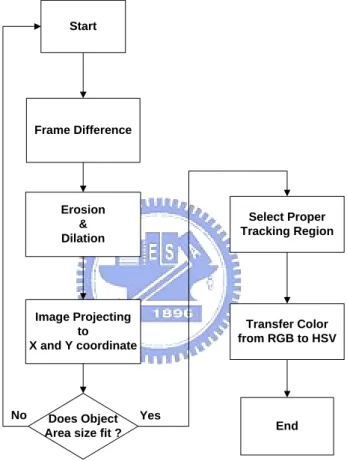
Frame Difference Erosion & Dilation Image Projecting to X and Y coordinate Yes No Start Select Proper Tracking Region Does Object
Area size fit ? End
Transfer Color from RGB to HSV
Figure 2-4 : The flow chart of motion detection
There are three major components in the motion detection. They are frame difference, specific digital filter and image projection. We can find the frame difference area between the previous frame and current frame by frame difference method. We can eliminate some noises by image processing techniques, dilation and erosion, after the frame difference method. We can then specify the moving object region by the image projection part.
II. Mean-Shift Tracking:
In this part, the mean-shift tracking find the most probable target position in the current frame by comparing the corresponding information with that of the object in the previous frame. The histogram in RGB color space is typically adopted for the comparison. But in order to reduce the sensitive to illumination problems, we adopt the HSV color space which could be used for solving the problem of illumination.
In this tracking approach, we need a similarity measure which can measure the difference between two distribution obtained by target color distribution model and current tracking object color distribution model. A popular measure is the Bhattacharyya coefficient [25, 26]. After this measurement, if the similarity is over 80%, successful tracking will be accepted; otherwise tracking failure and then resume a new process of detection. The flow chart of mean-shift tracking system is as shown in Figure 2-5.
Figure 2-5 : The flow chart of mean-shift tracking system
2.1.2 Camera Control
The purpose of camera control is to drive the active camera to keep the target object in the center of the monitor screen, especially when moving object is going to diverge from the center of the screen. So we divide the screen into 9 regions (as shown in Figure 2-6). If the target moving object is located on region E, the camera
will be set to stop. Otherwise, if the tracking is located on other regions (A, B, C, D, F, G, H, I), the camera is set to active to the specific directions (as shown in Figure 2-7).
Figure 2-6 : Divide screen into 9 regions
A B C
D E F
G H I
Figure 2-7 : 8 control directions for each region
Furthermore, the functions of zoom-in and zoom-out will be activated if the size of moving object changes. For example, if the tracking size is 2 times larger than the original size, we will activate the zoom-out action. Otherwise, if the tracking size is 1/2 time smaller than the original size, we will activate the zoom-in action. During the period of the active camera moving, the tracking system is still running as well as the camera control system. So, if the moving object changes its direction, we can easily
2.2 Hardware Platform
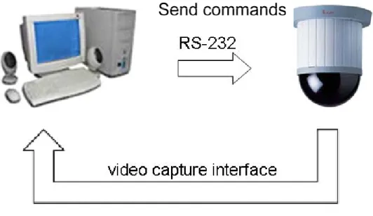
In this system, we use an active camera Lilin PIH-7600 High Speed PTZ Dome as shown in Figure 2-8 that has pan-tilt-zoom function to acquire real time image frame sequences. These frames are captured and processed by Personal Computer (PC). The specification of the computer is Intel Pentium(R) 4 at 2.4 GHz, 512 Mb RAM in Windows XP OS. As shown in Figure 2-9, the active camera has two interfaces which are RS-232 and video capture interface. RS-232 interface is used to send a command by PC to control the camera movement including pan-tilt and zoom operation. Meanwhile, video capture interface is an analog input of video sequence through video capture card on PC to read out the image data. The video capture card is Vguard 7146. To process the image and send commands to control the PTZ camera, we use the Borland C++ Builder 6.0 as the platform.
3
Chapter 3
Deformable Dynamic Tracking
System
In this chapter, we will describe how to determine the location and area of moving object, and track it by mean-shift algorithm in image sequence. The tracking system is divided into two parts: moving object detection and man-shift tracking. We use both frame difference method for moving object detection and size adaptive mean-shift method for tracking.
3.1 Moving Object Detection
Among most moving object detection methods, the most commonly used methods are frame difference method and background subtraction method. We use the frame difference method because the scene of an active camera always changes, so we can not construct a stable background model for background subtraction. This moving object detection part consists of three elements, which are temporal difference, specific filter and image projection.
Temporal difference calculates the image difference between current and previous frame as shown in Figure 3-1(a) and Figure 3-1 (b) on the next page. After the temporal difference step, we can see the noises in the difference map (as shown in Figure 3-2). If we directly use this to select the tracking region for moving object tracking, the performance might be undesirable.
Figure 3-1 : (a) previous frame (left) (b) current frame (right)
Figure 3-2 : The result of frame difference in Figure 3-1
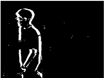
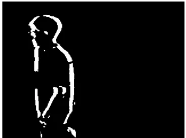
After we get the difference map, we use a specific digital filter of image dilation and erosion to eliminate the effect of noises on the difference map and then to enhance the actually moving object region. The result of applying this specific digital filter is shown in Figure 3-3 whose pixels are separated into two categories, moving pixels and non-moving pixels. We can compare Figure 3-2 with Figure 3-3 to see that the latter one is easier to recognize a moving object area for us.
Figure 3-3 : Difference map after erosion and dilation
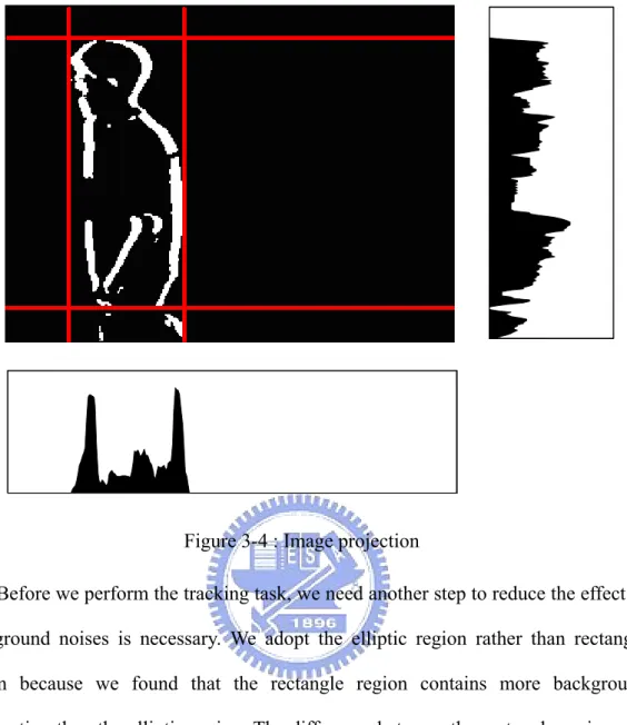
We can get the more precise difference map after this specific digital filter, and take action to select our target object for tracking tasks. The method we adopt is the image projection method, which is commonly used in image processing. We need to do horizontal projection and vertical projection and according to these two graphs we can mark the moving object region for later tracking tasks. The result of image projection method is shown in Figure 3-4.
In extracting the moving object region, we first take horizontal projection to find the largest region on X coordinate, and then perform the vertical projection to find the largest region on Y coordinate. The result is a rectangular bounding box from left-top coordinate to right-bottom coordinate as shown in Figure 3-4.
After finding the largest region of the motion binary map, we will take it as our target object for the mean shift tracking task, if the area of the region is larger than some scale and satisfy the appropriate width/height ratio. Otherwise if the size is too small or the width/height ratio is not reasonable, we will choose to resume the whole step to find another appropriate candidate moving object.
Figure 3-4 : Image projection
Before we perform the tracking task, we need another step to reduce the effect of background noises is necessary. We adopt the elliptic region rather than rectangle region because we found that the rectangle region contains more background information than the elliptic region. The difference between the rectangle region and the elliptic region can be seen in Figure 3-5. In chapter 5, the experiment result will demonstrate the advantage of using the elliptic region.
3.2 HSV Color Transformation
After we find the target object in the moving object detection part, we will track this target. However, we need to transfer the color space of our target object from RGB (Figure 3-6) to HSV (Figure 3-7) before tracking. The main purpose of this color space transformation is about the lightness problem of our system. Because the diaphragm of the active camera which we use will be changing by itself with the environment illumination, we have to avoid the effect of this varying factor. Consequently, we solve this problem by using the HSV color space, because it can extract the lightness information from RGB color values, so we can reduce the sensitivity of this single quantity of illumination.
The HSV model, also known as HSB model, was created in 1978 by Alvy Ray Smith. It is a nonlinear transformation of the RGB color space. It defines a color space in terms of three components: hue, saturation, and value. The definition is described below: [27]
1. Hue: It is the color type and ranges from 0 ~ 360 degree. Each value corresponds to one color. For example, 0 is red, 45 is orange and 55 yellow. When it comes to 360 degree, it is also equal to 0 degree.
2. Saturation: It is the intensity of the color, and ranges from 0%~100%. 0 means no color, and that means only gray value between black and white exists. 100 means the intense color with the most color variety.
3. Value: It is the brightness of the color, and also ranges from 0%~100%. 0 is always black. Depending on the saturation, 100 may be white or a more or less saturated color.
Figure 3-6 : RGB color model [28]
Figure 3-7 : HSV color model [29]
In our system, we transfer the RGB color space of the target object to HSV color space in order to prevent the brightness problem caused by the varying diaphragm of the camera, because the HSV color model separates the brightness information from the RGB color information. The transformation algorithm from RGB color model to HSV color model lists out step by step in the following paragraph:
1. We will transfer the RGB value from 0~255 to 0.0~1.0.
2. We select the maximum and minimum value of (R, G, B), and then adopt the following algorithm to transfer the RGB model to HSV model.
0
if
MAX = MIN
60 ×
MIN
MAX
B
G
−
−
+ 0 if
MAX = R , G≧B
3.H =
60 ×
MIN
MAX
B
G
−
−
+ 360 if
MAX = R , G<B
60 ×
MIN
MAX
R
B
−
−
+ 120 if
MAX = G
60 ×
MIN
MAX
G
R
−
−
+ 240 if
MAX = B
( 3.1 ) 4.0,
if MAX = 0
1-
=
S
MAX MINotherwise
(3.2) 5.
V = MAX
(3.3) 6. In step 3, if MAX=MIN the value of H will consider as “Undefined.” Inorder to let our calculation more convenient, we define the H value to be 0 if it happens.
After execute these 6 steps to transfer the RGB color of our target object into HSV color, the next step of our system is to calculate the color histogram of the target object pixel by pixel. And the most important problem of this step is how many orders each element of HSV color model will be. This problem will be solve and explained in the Chapter 5.
3.3 Mean-Shift Tracking
The mean shift method is employed in the joint, spatial-range domain of gray level and color images for discontinuity preserving filtering and image segmentation before by goodness of its low cost and simplicity in computation. This method also presents a new approach to the real time tracking of non-rigid objects whose statistical distributions characterize the object of interest [16]. This theorem was proposed in 2000, and it also has been proved that it will converge consequently.
3.3.1 Mean-Shift Tracking Theorem
By definition, given a set { Xi }i=1…n of n points in the d-dimensional space Rd,
the multivariate kernel density estimate with kernel K(x) and window radius h, computed in the point X0 is given by
∑
= ∧−
⋅
=
n i i uh
x
x
k
h
n
q
1 2 0)
(
1
(3.4)where a commonly used kernel is the multivariate normal:
) 2 1 exp( ) 2 ( ) ( /2 2 x x K =
π
−d ⋅ − (3.5)The kernel value of the candidate object at position Y can be described as:
∑
= ∧−
⋅
=
n i i uh
x
Y
k
h
n
Y
p
1 2)
(
1
)
(
(3.6)Hence, tracking can be seen as searching the minimized distance of the sample based on the estimate of the Bhattacharyya coefficient given by:
∑
=⋅
=
=
m u u uy
q
p
q
y
p
y
1)
(
]
),
(
[
)
(
ρ
ρ
(3.7)We do Taylor Expansion at point ˆpu
( )
ˆy and get: 0∑
∑
= =+
⋅
≈
m u u u u m u uy
p
q
y
p
q
y
p
q
y
p
1 0 1 0)
(
)
(
2
1
)
(
2
1
]
),
(
[
ρ
(3.8)After some derivations, we see that:
∑
∑
= =⎟
⎟
⎠
⎞
⎜
⎜
⎝
⎛ −
⋅
+
⋅
≈
m u i i h m u uh
x
y
k
w
C
q
y
p
q
y
p
1 2 1 02
)
(
2
1
]
),
(
[
ρ
(3.9) where∑
==
m u u u iy
p
q
w
1(
0)
(3.10)So we can use this to minimize the distance by mean-shift algorithm.
3.3.2 Mean-Shift Tracking Algorithm
In our system, we use the mean-shift algorithm to track the object that we are interested in. After color model transformation, we use the histogram of HSV color space to excute the mean-shift tracking. In the context of tracking, given the color distribution functions of q and p generated from the model and candidate object regions, a sample corresponds to the color observed at a pixel X and has an associated sample weight w(x) which is defined by:
))
(
(
/
))
(
(
)
(
x
q
I
x
p
I
x
w
=
(3.11)The key point of the mean-shift algorithm is the computation from initial object position X to a new location X . The mean-shift vector ΔX = X − is computed by X
the following formula:
∑
∑
⋅
−
−
⋅
⋅
−
=
Δ
i i i i ix
w
X
X
K
X
X
x
w
X
X
K
X
)
(
)
(
)
(
)
(
)
(
(3.12)where K(.) is usually a radically symmetric kernel function, such as a Gaussian distribution kernel function. We choose another popular kernel function called flat kernel. That is { K(x) = 1 , ||x|| < 1 }.
We will repeat the algorithm several times until it converges, and it will converge soon provably [16]. After its converging, we also need to check if the tracking result matches with our tracking target. We estimate the discrete density q={qu} u=1…m from
the m-bin histogram of the target model, while p(y)={qu(y)}u=1…m is estimated at a
given location y from m-bin histogram of the target candidate.
So the whole mean-shift algorithm can be briefly sorted below:
I. Transfer the HSV color model into distribution histogram on target model. II. For the coming frames, get the HSV color histogram of the target candidate. III. Calculate the mean-shift vector ΔX using the formula (3.12)
IV. After it converges, calculate the Bhattacharyya coefficient using the following equation (3.7) to see if the target candidate and the target model are matched.
V. If the target candidate is matched, perform the next adaptive size selecting method. Otherwise we consider the tracking is loss and search for another moving object.
3.4 Adaptive Size Selecting
After the mean-shift tracking step, the next step of our tracking system is the adaptive size selecting step, which is also our innovation. In the previous step, mean-shift tracking step, we can only track the target object in fix size matching. Because we should track the target object as precise as possible, we need to change our tracking region with the varying size. Eventually, we find a solution for this problem by combining the mean-shift tracking with adaptive size selecting method.
The adaptive size selecting method is also based on the mean-shift tracking algorithm. In general, the mean-shift tracking algorithm selects the fix size target candidate to calculate the mean-shift vector ΔX. Here we use the different tracking sizes of target candidate, and we calculate the Bhattacharyya coefficient for each size. As shown in Figure 3-8, after we calculate the position of new tracking object, we will choose several candidates with different size.
There are three different size candidates in Figure 3-8, the smaller candidate, the normal candidate and the larger candidate. Then we need to compare their Bhattacharyya coefficients to choose which one has the largest similarity. Before that, the most important thing is to normalize the color distribution of each tracking size of the candidate, because the Bhattacharyya coefficient which we use for judging the similarity of each candidate must have the same numbers of sample weight. So the each bin of color distribution of target candidate p(y)={qu(y)} u=1…m will be multiplied
a normalized coefficient f.
f = number of target model pixels / number of target candidate model pixels
Therefore the Bhattacharyya coefficient calculating equation will be modified as:
∑
= ⋅ ⋅ = ⋅ = m u u u y q p f q y p f y 1 ) ( ] ), ( [ ) (ρ
ρ
(3.10)We compare the Bhattacharyya coefficients calculated by equation (3.10) of three different sizes of target candidate, and then we select the one which has the largest Bhattacharyya coefficient as our final tracking result.
In the Figure 3-9 and Figure 3-10 on next page, we demonstrate the result of size selecting on single picture. Figure 3-9 is retrieved on Internet and Figure 3-10 is enlarged from Figure 3.9 by Photoshop. In the Figure 3.10, the tracking region is chosen by hand and the right one is the target object. We use both the mean-shift tracking and size selecting method to calculate the correct position and size. In Figure 3-10, after 4 times iteration we can see the tracking result is good and the size selecting is also matched.
Figure 3-10 : The tracking result after 4 times iteration.
This selecting method also has some problems that might occur. They would happen in some video sequence which leads to the size selecting always diverging. That means the size selecting step always choosing the larger region or choosing the smaller tracking region. Both situations may cause the size selecting diverging and tracking failure. We can not simulate this kind of situation in only one picture because that might happen in many frames later. But we can handle this by the following two methods:
1. We can try to change the camera zoom to let the camera reset its focus and refine the image resolution of the target object. This method might be useful when the distance between the target object and the camera
varies very often, but this method still might be failure possibly.
2. We can restrict the size selecting times in our coding program such as only 3 times larger than the target object or only 3 times smaller than the target object. This method seems not very good but its purpose is to prevent the tracking diverged and failure.
We adopt both steps to our tracking system, and the result is the same with our expectation. The experiment result will be demonstrated in the Chapter 5 with more discussions.
4
Chapter 4
PTZ Control System
In the proposed tracking system, we try to keep the tracked target around the central part of the captured scene. In this chapter, we will introduce the control mechanism of an active pan-tilt-zoom camera module. The control mechanism includes the pan/tilt action and the zoom in/out action. The pan and tilt control action of the active camera will be activated in two conditions: one is when the change detection found a moving object and its position is not at the center part of the captured scene. The other condition is when the result of the mean-shift tracker found the target away from the center. The zooming in and out control action of the active camera will be activated by the result of size selected module.
Despite of the action control of the camera, the speed control of these actions is also concerned. That is, the speed of pan/tilt action is switched dynamically and proportional to the distance between the target position and the image center. A larger panning/tilting speed is required when the target is farer away from the center. At the same time, the speed of zooming in/out action also needs to be changed dynamically and proportional to the size-changing rate of our target object. After having calculated and decided the proper pan/tilt speed, the camera control module executes some control routines to control the active camera continuously.
4.1 Basic Mechanism
The camera we use is the Lilin PIH-7600 High Speed PTZ Dome, and its control signal is transmitted by RS-485 standard interface. To connect this camera to our PC, we use RS-232 serial port and a transfer connector between RS-232 and RS-485. The UART Format is: none parity bit, 8 data bits, 1 stop bit, and baud rate: 9600 bps.
Every command that we send from PC to camera contains three bytes, and it usually accompanies with a “STOP” command after every command has been send. The detail of each byte of controlling command is listing in Figure 4-1 and Figure 4-2. We can see the function of each byte in Figure 4-1 and the speed control of pan and tilt in Figure 4-2.
Byte1 Receiver Address 40 H
Byte 2 Control Byte 1
Bit-0 Æ Pan - Right Bit-1 Æ Pan - Left Bit-2 Æ Tilt - Up Bit-3 Æ Tilt - Down
Byte 3 Control Byte 2 Speed Control Figure 4-1 : Command Description
Tilt Speed Bit 5 Bit 4 Bit 3 Pan Speed Bit 2 Bit 1 Bit 0 0.2゚/sec 0 0 0 0.2゚/sec 0 0 0
2゚ /sec 0 0 1 2゚ /sec 0 0 1 8゚ /sec 0 1 0 8゚ /sec 0 1 0
20゚/sec 0 1 1 20゚/sec 0 1 1
※Default : Bit 7 = 1 Bit6 = 0
The most challenging part of the active camera control is the panning/tilting speed and its active time. If the tracking speed is set too fast and the active period is set too long, the tracking might be lost because the panning/tilting action is taken too much. On the other hand, if the tracking speed is set too slow to follow with the target object, we lost it as well. After our experiments, we select the 2°/sec on pan speed and 8°/sec on tilt speed and that will be the optimized solution.
In our tracking system, we use mean shift tracking method to find the target object in every frame. Then we divide our monitor into 9 difference region as showed in Figure 4-3. If the target object moves away from the center, that will motivate us to drive the active camera to track the object. After the position tracking, we also need to judge the size change of our target object. If the size changes twice larger than the original one, we zoom out the camera. On the other hand, if the size becomes smaller than the half of original one, we zoom in it.
4.2 Pan and Tilt Control
In Pan and tilt control, we are according to the position of tracking object. And the command format that we sent has been described in the former articles. In Figure 4-4, we illustrate the flow chart of pan and tilt control, and in Figure 4-5, we list out the command format and content of panning right, panning left, tilting up, tilting down and stop command.
Figure 4-4 : Pan and tilt control (position control)
Here are three control issues that we should pay more attention to when we send commands to control the active camera.
I. The speed control of pan and tilt are optimized as 2°/sec on pan speed and 8° /sec on tilt speed. When the speed is set to be higher, the image will be blurred due to the shortage exposure time of the camera. If the speed is set to be lower, the tracking will be easily got lost because the tracking speed is not enough to follow the moving object.
II. When we find out that the moving object has already been tracking in the center of the monitor, we have to send a “STOP” command no matter the action of the camera.
III. When we find out that the moving object has changed its position to another region, despite the center region, we should change our sending command to control the action of the active camera immediately.
Panning-Right Tilting-Up Stop Command
40H 01H 81H 40H 04H 81H 40H 00 H FF H
Pan Speed : 2°/sec Pan Speed : 8°/sec
Panning-Left Tilting-Down
40H 02H 81H 40H 08H 81H
Pan Speed : 2°/sec Pan Speed : 8°/sec
4.3 Zoom control
The zoom in/out function will cooperate with the size selecting function of the tracking task. At the end of the tracking task, we need to determine if the size of target object become larger or getting smaller. As a matter of course, if the size of our target object becoming larger than some scale, we need control the camera to do the zoom out action. Otherwise, we do the zooming in action. For example in Figure 4-6, the size of the target object is too large, so we need to send the zoom out command. On the other hand in Figure 4-7, we need to perform the zoom in action.
Figure 4-6 : The target size is too large
The zoom in/out control method of this active camera is similar to the pan/tilt control method, but the difference is at the speed control of zoom. Figure 4.8 illustrates the controlling command of zoom-in, zoom-out and stop command. The difference between the Figure 4-8 and Figure 4-1 is that there is no speed control parameter fro the zoom control. The Figure 4-9 shows the flow chart of the function of zoom in/out control.
Zoom-In Zoom-out Stop
40 H 10 H FF H 40 H 20 H FF H 40 H 20 H FF H
There is no speed control for zoom in or zoom out because its default setup, so we can only adjust the duration time of zoom in/out function to control the ratio of zoom. In Figure 4-9, we can see that after we sent a zoom in/out command, the camera will execute the zoom action until we send a stop command to terminate this action. Generally it takes 100 ms in every reasonable zoom period.
5
Chapter 5
Experimental Results
Because our moving object tracking system will run in real time video surveillance with an active pan-tilt-zoom camera, we should do some experiments to test its performance and stability under several kinds of environments. In this chapter, we will introduce the setup of our tracking system and define our experimental environment in section 5.1 and then compare our HSV color space to traditional RGB color space model in section 5.2.
In section 5.3, we will experiment our modified tracking method in real time tracking environment with an active PTZ camera and see the difference between our method and classical mean-shift tracking method. Finally, we will make a discussion in section 5.4.
5.1 The Experimental System
Our automatic tracking system is using the following components:
z The system uses Lilin PIH-7600 High Speed PTZ Dome active camera for capturing image sequence. The sequence is composed of 320x240 color image acquired at a frame rate 30 frames per second.
z The system is developed in Borland C++ Builder 6 and has been tested on color image sequences acquired on indoor environments.
z The system has been implemented on an Intel Pentium(R) 4 CPU running at 2.4 GHz with 512 Mb RAM and a real time video capture card under Windows XP SP2 OS.
z The active camera has two I/O interfaces which are RS-485 and video-out. The RS-485 interface is used to drive the pan-tilt-zoom camera, but unfortunately, most PC does not support this specification (RS-485) so we use a RS-485 to RS-232 transfer connector to change our control signal format from RS-232 to RS-485. With respect to the video-out interface, it is an analog video output from the camera, so we can capture the real time video sequence through this video-out interface.
5.2 Environment Setup
The environment of our experimental locates in our laboratory. The complexity of the environment is enough to verify our system while tracking and detecting moving human. Figure 5-1, Figure 5-2 and Figure 5-3 show several images of our lab environment without zoom in/out operation. Figure 5-4, Figure 5-5 and Figure 5-6 show several images for zoom in/out condition.
Figure 5-2 : Experimental environment II
Figure 5-3 : Experimental environment III
Figure 5-5 : Zoom condition II
Figure 5-6 : Zoom condition III
The zoom in/out operation level of the pan-tilt-zoom camera which we use is analog controlled. We can control the zoom level by controlling the timing of stop command sending. For example, if we want to just zoom in only a little bit, we could send a stop command a short time, like 30ms, after sending the zoom in command. On the other hand, we could send a stop command a long time, like 300ms, after sending the zoom in command if we want to zoom in a lot. For control convenience, we separate the zoom in/out operation into about 9 stages for the overall system. Figure 5-7 shows a sequence of the total zoom operation.
Figure 5-7 : 9 stages of zoom in/out operation
5.3 Tracking Region Experiment
In our tracking system, we adopt the ecliptic tracking region rather than the rectangle one. We will do some experiments to prove the ecliptic tracking region which we use is better in both calculating loading and tracking performance. In this experiment, we will use a recorded video sequence because we need to confirm the all tracking situation variables are fixed and the only control variable is the tracking region. Here are our experiments:
I. We use the same video and the same original target object for the ecliptic tracking region or the rectangle tracking region to see which performance is more reliable, and show up in Figure 5-8 for the ecliptic tracking region and
in Figure 5-9 for the rectangle tracking region. We will find that the tracking failure will occur in Frame 432 by using rectangle tracking region.
Figure 5-9 : Tracking result using ecliptic region
II. We try to analysis the iteration number of mean shift tracking system by comparing the rectangle tracking region, single layer weighting ecliptic tracking region and double layer weighting layer ecliptic tracking region. In
Figure 5-10, we can see the difference between these three tracking region and in Figure 5-11 we can find that the method of double layer weighting layer ecliptic tracking region has the best performance.
Figure 5-10 : Coordinate definitions and three different tracking regions
(X1, Y1) (X2, Y2) Rectangle Single Ecliptic Double Ecliptic (97, 52) (152, 142) 2.14 1.99 1.63 (100, 52) (148, 147) 2.19 2.06 1.56 (99, 44) (150, 127) 2.02 1.93 1.75 (99, 47) (150, 134) 2.04 1.96 1.61 (100, 46) (152, 141) 2.12 Tracking lost 1.60 (93, 48) (150, 138) Tracking lost 1.99 1.72 (96, 48) (152, 135) Tracking lost 1.98 1.65 (101, 52) (146, 144) 2.16 2.03 1.56 (95, 46) (152, 139) 2.05 1.99 1.67 (102, 64) (145, 141) 1.95 1.94 1.49 (101, 49) (144, 149) 2.18 2.04 1.67 (100, 45) (151, 137) 2.12 1.98 1.64 (99, 50) (153, 138) 2.09 1.90 1.61 (97, 49) (147, 146) 2.15 1.96 1.59 (101, 45) (149, 139) 2.11 1.99 1.63
Average Iteration Times 2.10 1.98 1.62 Figure 5-11 : Iteration time comparison (unit: times)
5.4 Color Space Experiment
In our system, we execute the transformation form the RGB color space to HSV in order to reduce the changing of the environment illumination having influence on our mean-shift tracking algorithm. Now, we will demonstrate the experimental result in Figure 5-12. In Figure 5-12, because the illumination of the target changes only a little bit, we can see that the tracking result of the mean-shift algorithm seems so far so good.
In Figure 5-13, when the illumination of the target changes a lot more, we can see that the tracking result of the mean-shift algorithm seems getting worse. In this case, we can find that the illumination influences the mean-shift tracking algorithm a lot, but this illumination effect is hard to find by human eyes actually. In this experiment, we can explain why we adapt the HSV color space rather than RGB color space. In Figure 5-13 shows up the result of using HSV color space.
RGB Tracking Result HSV Tracking Result
RGB Tracking Result HSV Tracking Result
5.5 Fix Size Tracking Experiment
In this experiment, we demo our tracking system which combines the video sequence analysis and automatic camera tracking control. Moreover, we adapt fix size tracking in this experiment, turn off the function zoom in/out and only use the automatic pan-tilt control for the active camera. In Figure 5-14 and Figure 5-15, we can see the result of this experiment and this tracking result will not influenced by the dynamic background.
In Figure 5-15, we can find that although we do not choose the tracking region perfectly matched the target object in the reference frame, we still can track this target well under similar color background and many people interrupting in.
Figure 5-15 : Fix size tracking result (sequence 2)
In Figure 5-16, the result of single target tracking is demonstrated and the difference between Figure 5-16 and Figure 5-15 is the covering and disturbance becoming more complex and tough.
5.6 Adaptive Size Tracking Experiment
In Figure 5-17, the result of adaptive size tracking is demonstrated and the major point of this section is the camera can not only automatically track target object by position, but also track target object by size, so we can keep the size almost the same by controlling the function of zoom in/out.
6
Chapter 6
Conclusions and Future Works
6.1 Conclusions
The experimental results show that the proposed system is capable of tracking moving object smoothly by an automatic controlled active camera. At the same time, the system also works well even if the target has some disturbances on its illumination and shape. There are several contributions made out of this research:
1. We provide a smooth camera tracking system.
2. Our system can locking on specific moving object, and does not be affected by illumination and background variables.
3. We proposed a modified mean-shift tracking algorithm, and that can be used for real time moving object tracking in both position and size selecting.
4. Our system can handling following conditions on tracking:
i. Camera acting
ii. Some illumination changing
iii. Getting some covering noises
6.2 Future Works
So far, our tracking system works in indoor environment with one moving target although it still can do position tracking and size selecting, but when this target get some covering noises and become farer or closer to the camera at the same time, the proposed system can not track it well because we can not tell which situation occurs, covering disturbance or target size changing. In order to solve that problem, we must deal with the target object recognition problem and then we can know whether the target changes its size or it is covered by something else. The most suitable target object recognition system will be the human detection system for the indoor environment security surveillance system.
For setup convenience, this whole tracking algorithm can also be ported on some portable devices such as DSP platforms. That will be more suitable for real surveillance application and it also can be combined with more than one camera to enhance the tracking reliable intensity.
References
[1] Li, C. I., and Wang S. J., “Detection and Tracking of a Single Deformable Object on an Active Surveillance Camera,” 16th IPPR Conference on Computer Vision, Graphics and Image Processing (CVGIP 2003), 17~19 August, Kinmen, ROC
[2] Segen, J. “A camera-based system for tracking people in real time,” Pattern Recognition, 1996, Proceedings of the 13th International Conference, Volume 3,
25-29 Aug. 1996 Page(s):63 - 67 vol.3
[3] Daniilidis, K., Krauss, C., Hansen, M., and Sommer, G., “Real-Time Tracking of Moving Objects with an Active Camera,” Real-Time Imaging, Volume 4, Number
1, February 1998, pp. 3-20(18)
[4] Stauffer, C., and Grimson, W.E.L., “Adaptive background mixture models for real-time tracking,” Computer Vision and Pattern Recognition, 1999. IEEE
Computer Society Conference on Volume 2, 23-25, June 1999
[5] Scheutz, M., McRaven J., and Cserey G.. “Fast, reliable, adaptive, bimodal people tracking for indoor environments,” in Proc. of the IEEE International Conference on Intelligent Robots and Systems, vol. 2, Oct. 2004, pp. 1347-1352.
[6] Comaniciu, D., Ramesh, V., and Meer, P., “Real-time tracking of non-rigid objects using mean shift,” in Proc. IEEE Conf. on Computer Vision and Pattern Recognition, Hilton Head, SC, volume II, June 2000, pp. 142–149.
[7] Po, L. M. and Ma, W. C., “A novel four-step search algorithm for fast block motion estimation,” IEEE Trans. Circuits System Video Technology, vol. 6, pp.
313-317, June 1996.
[8] Ghanbari, M., “The cross-search algorithm for motion estimation,” IEEE Trans. Commun., vol. 38, pp. 950-953, July 1990.
matching motion estimation,” Image Processing IEEE Transactions, page(s):
287-290, Feb 2000.
[10] Zhu, C., Lin, X., and Chau, L. P., “Hexagon-based search pattern for fast block motion estimation,” Circuits and Systems for Video Technology IEEE Transactions,
page(s): 349-355, May 2002.
[11] Po, L. M., and Ma, W. C., “A novel four-step search algorithm for fast block motion estimation,” Circuits and Systems for Video Technology IEEE Transactions,
page(s): 313-317, Jun 1996
[12] Foresti, G. L., Micheloni, C., Snidaro, L., and Marchiol, C., “Face detection for visual surveillance,” in Proc. of the 12th IEEE International Conference on Image Analysis and Processing, Sept. 2003, pp. 115-120.
[13] Chien, S. Y.,Ma S. Y., and Chen, L. G., “Efficient Moving Object Segmenttation Algorithm Using Background Registration Technique,” IEEE Trans. On Circuits and System for Video Technology, Vol. 12, No. 7, July 2002.
[14] Comaniciu, D. and Meer, P., “Mean Shift: A Robust Approach Toward Feature Space Analysis,” IEEE Trans. Pattern Analysis and Machine Intelligence, Vol. 24,
No. 5, May 2002.
[15] Cheng, Y., “Mean Shift, Mode Seeking, and Clustering,” IEEE Trans. Pattern Analysis and Machine Intelligence, Vol 17(8), pp.790-799, August 1995.
[16] Comaniciu, D., Ramesh, V., and Meer, P., “Real-time tracking of non-rigid objects using mean shift,” IEEE Conference on Computer Vision and Pattern Recognition, vol. II, Hilton Head, SC, June 2000, pp. 142-149.
[17] Fukanaga, K. and Hostetler, L.D., “The Estimation of the Gradient of a Density Function, with Applications in Pattern Recognition,” IEEE Trans. Information Theory, Vol 21, pp.32-40, 1975.
Interface,” IEEE Workshop on Applications of Computer Vision, Princeton, NJ,
1998, pp.214-219.
[19] Collins R. T. “Mean-Shift blob tracking through scale space,” In IEEE International Conference on Computer Vision and Pattern Recognition, 2003,
p.234~p.240.
[20] Lindeberg, T., “Feature Detection with Automatic Scale Selectio,” International Journal of Computer Vision, Vol 30(2), pp.79-116, November 1998.
[21] Bretzner, L. and Lindeberg, T., “Qualitative Multiscale Feature Hierarchies for Object Tracking,” Journal of Visual Communication and Image Representation,
Vol 11(2), pp.115-129, June 2000.
[22] Katja, N., Esther, K. M., and Luc, V. G., “An Adaptive Color-based Particle Filter, ” Image and Vision Computing, vol. 21, pp.99-110, 2002
[23] Isard, M. and Blake, A., “Contour Tracking by Stochastic Propagation of Conditional Density,” European Conference on Computer Vision, 1996,
p.343-356.
[24] Isard, M. and Blake, A., “CONDENSATION Conditional Density Propagation for Visual Tracking,” International Journal on Computer Vision, Page 5-28, 1998
[25] Thacker, N. A., Aherne, F. J. and Rockett, P. I., “The Bhattacharyya Metric as an Absolute Similarity Measure for Frequency Coded Data,” STIPR97, 1st International Workshop on Statistical Techniques in Pattern Recognition, Prague,
Czech Republic, 1997.
[26] Kailath, T., “The Divergence and Bhattacharyya Distance Measures in Signal Selection,” IEEE Transactions on Communication Technology, p.52-60, 1967.
[28] http://student.kuleuven.be/~m0216922/CG/color.html#The_RGB_Color_Model [29] http://en.wikipedia.org/wiki/Image:HSV_cone.png
![Figure 3-7 : HSV color model [29]](https://thumb-ap.123doks.com/thumbv2/9libinfo/8237130.171196/30.892.247.647.492.818/figure-hsv-color-model.webp)
