考量移動特性於耐延遲網路之團隊省電機制設計 - 政大學術集成
53
0
0
全文
(2) 考量移動特性於耐延遲網路之團隊省電機制設計 Energy‐aware Grouping Design By Considering Moving Pattern for Delay Tolerant Networks 研 究 生:劉勇麟. Student:Yung‐Lin Liu. 指導教授:蔡子傑. Advisor:Tzu‐Chieh Tsai. 國立政治大學 資訊科學系 碩士論文. 學 y. sit. Nat. . ‧. ‧ 國. 立. 政 治 大. n. er. io. A Thesis submitted to Department of Computer Science al v i n Ch National Chengchi University engchi U in partial fulfillment of the Requirements for the degree of Master in Computer Science . 中華民國一百年七月 July 2011 .
(3) 立. 政 治 大. ‧. ‧ 國. 學. n. er. io. sit. y. Nat. al. Ch. engchi. i n U. v. .
(4) 立. 政 治 大. ‧. ‧ 國. 學. n. er. io. sit. y. Nat. al. Ch. engchi. i n U. v. . .
(5) 考量移動特性於耐延遲網路之團隊省電機制設計 摘要 . 在傳統的 DTN 路由協定中,由於網路拓樸的快速變動,為了能將 訊息封包傳送到目的地,通常是透過大量的複製,或是透過資訊的過. 政 治 大. 濾與計算,將封包交由適合的節點來協助傳送。. 立. 然而在電池電源有限的條件之下,過於冗餘的封包複製傳遞,或. ‧ 國. 學. CPU 運算的大量使用,將使得節點容易因電量耗盡而失去傳遞的功能,. ‧. 不只是造成整體系統的存活時間(System Lifetime)降低,亦非常不利於. sit. y. Nat. 維持整體網路的傳遞成功率(Delivery Ratio)。. er. io. 在旅行的過程中,同行的人們通常具有相同的移動軌跡以及最終. al. n. v i n Ch 目的地,因而形成團體行動的模式;針對這樣的特性,我們採用每個 engchi U 團隊只留下一位領隊來統籌探索鄰居及封包傳遞的概念,透過 GPS 的資訊輔助來設計出組隊省電機制,延長節點存活時間,進而提升系 統存活時間,並在運算複雜度較低且封包冗餘複製亦降低的狀況下, 仍保有不錯的傳遞成功率以及較低的效能衰減。 關鍵字:耐延遲網路、省電、團隊、路由協定 . i .
(6) Energy-aware Grouping Design By Considering Moving Pattern for Delay Tolerant Networks. Abstract In traditional routing protocols of DTNs, most of them are using redundancy messages and information computing to make a good relay. 政 治 大 Due to energy limitation, 立 too many redundant message transmissions. decision.. ‧ 國. 學. or high computing will make nodes die off quickly. It will decrease the system lifetime and diminish the delivery ratio of the whole system.. ‧. When people go on a tour, friends always form a group due that. sit. y. Nat. members have a similar moving path and destination. Based on the features of moving patterns, we design a grouping scheme, namely,. er. io. n. Energy-aware Grouping, a with the concept that there v is only one node. i l C n U transmissions. With awake in a group in charge ofhcontact e n g cand h imessage the assistance by GPS, our method has reduced the numbers of redundant message transmissions and information computing. Simulation results show that it can extend the system lifetime with maintaining still good delivery ratio.. Keywords:Delay Tolerant Network, energy-aware, group, routing protocol. ii .
(7) 致謝辭 研究生的旅程轉眼就告一個段落,學生生涯也正式畫下句點。雖然同 屬電資類別,但從大學的電機工程要轉到資訊科學,仍是有許多門檻存在; 所幸有許多人的提攜與厚愛,讓我得以順利取得碩士學位。 首先必須要感謝的是父母親,不但包容我的任性,也支持我的選擇, 讓我沒有後顧之憂地專心學業。 論文指導教授 蔡子傑老師的辛苦,自當不在話下,即便日常的教務已. 政 治 大. 經使他相當疲憊,每次的 meeting 報告,依舊有著精闢的分析與建言,讓. 立. 嶇,由衷感謝 蔡子傑老師的諄諄教誨與提攜。 . 學. ‧ 國. 我們受益匪淺,若非老師不厭其煩的耐心引導,在研究路上相信會更加崎. 在此也要感謝所有一同相處過的學長姊 建家、松達、文卿、東諺、育. ‧. 晟、立誠,同屆的同學 界誠、泰榮、諭祺,學弟 志鴻、偉敦、凱禎、彥. y. Nat. a. er. io. 活變得豐富,祝福所有人都能健康、順心。 . sit. 嵩、欣諦、英明,以及所有一起打球的夥伴們,感謝你們讓枯燥的研究生. n. iv 最後,要感謝我的賢內助 l 帝妏與女兒 玥箴,你們的笑容是我不斷向. n U engchi 前邁進的動力泉源,平凡的幸福就是最佳的報酬;在沒有你們之前,生活. Ch. 目標模糊不清,渾噩度日;你們的到來,彷彿就像是黑暗中的唯一一盞明 燈,指引我前進的方向;未來還有著更多艱難的挑戰在等著我去突破,期 許自己能夠戰勝一切的不順遂,開拓璀璨的人生篇章。 . iii .
(8) LIST OF CONTENTS CHAPTER 1 Introduction.................................................................... 1 1.1 Background .............................................................................................. 1 1.2 Motivation ................................................................................................ 1 1.3 Our Goal ................................................................................................... 2 1.4 Organization ............................................................................................. 2 . 治. CHAPTER 2 Related Work政 ................................................................. 3 大. 立. 2.1 Flooding-based routing Protocol .............................................................. 4 . ‧ 國. 學. 2.1.1 Epidemic Routing Protocol .....................................................................4 . ‧. 2.1.2 Direct Contact Routing Protocol .............................................................4 . 2.2 Forwarding-based Protocol ...................................................................... 5 . y. Nat. io. sit. 2.2.1 Location-based Routing Protocol ............................................................5 . er. 2.2.2 Gradient Routing Protocol .......................................................................5 . n. a. iv. l C 2.2.3 Clustering and Cluster-Based Routing n Protocol for. hengchi U. Delay-Tolerant Mobile Networks ............................................................6 . 2.3 Wakeup scheduling in multi-hop wireless networks ................................ 6 2.3.1 Scheduled Rendezvous ............................................................................7 2.3.2 On-demand ..............................................................................................7 2.3.3 Asynchronous ..........................................................................................8 . CHAPTER 3 Energy-aware Grouping Design .................................. 10 3.1 System Model ......................................................................................... 11 3.2 Moving Pattern ....................................................................................... 11 iv .
(9) 3.2.1 Scenario 1:Nodes Never Depart .........................................................12 3.2.2 Scenario 2:Nodes May Depart or Join ................................................12 3.2.3 Scenario 3:Nodes Move Randomly ....................................................12 . 3.3 Energy-aware Grouping (EG) Design .................................................... 14 3.3.1 Methods choose when contact between method 1 (M1) and method 2 (M2) .......................................................................................15 3.3.2 Method 1 (M1) for less variation ...........................................................16 3.3.3 Method 2 (M2) for the environment with groups will change ..............18 . 政 治 大. 3.4 Message Relay Policy ............................................................................ 20 . CHAPTER 4 Simulation 立 and Results ................................................ 22 . ‧ 國. 學. 4.1 Simulation Setup .................................................................................... 23 4.1.1 General Settings of Simulator................................................................24 . ‧. 4.1.2 Parameters about Energy Consumption.................................................25 . Nat. sit. y. 4.2 Simulation Results.................................................................................. 26 . er. io. 4.2.1 Nodes Never Depart ..............................................................................26 . n. 4.2.2 Nodes MayaDepart or Join ..................................................................... 31 iv l. n U e n......................................................................... 4.2.3 Nodes Move Randomly 35 gchi. Ch. CHAPTER 5 Conclusions and Future Work ...................................... 38 5.1 Conclusion .............................................................................................. 38 5.2 Future Work ............................................................................................ 38 . References ....................................................................................... 39 . v .
(10) LIST OF TABLES Table 1:Parameters of simulation setting ........................................ 24 Table 2:Parameters of energy consumption .................................... 25 Table 3:Summary of the end in Scenario 1 (Without nodes depart from groups) .......................................................... 29 Table 4:Summary of the end in Scenario 2 (Nodes may depart)..... 33. 政 治 大 Table 5:Summary of the end in Scenario 3 (Nodes move 立 ‧. ‧ 國. 學. randomly). ........................................................................ 37. n. er. io. sit. y. Nat. al. Ch. engchi. vi . i n U. v.
(11) LIST OF FIGURES Figure 1:On-demand wakeup scheduling.......................................... 7 Figure 2:The tuple (W,C,K) as the sleep pattern in CAPM............... 8 Figure 3:Neighbor discovery ............................................................ 9 Figure 4:Overview of Energy-aware Grouping (EG)...................... 14 Figure 5:The flow of method 1 (M1) .............................................. 16. 政 治 大 Figure 6:The flow of method 2 (M2) .............................................. 18 立. ‧ 國. 學. Figure 7:Message Relay Policy ....................................................... 20. ‧. Figure 8:A snap shot of the ONE simulator. ................................... 23. sit. y. Nat. Figure 9:Number of dead nodes in scenario 1 (Nodes never. er. io. depart). ............................................................................. 27. a. n. v l C in scenario 1 (Nodes Figure 10:Delivery ratio n i never depart). ......... 28 hengchi U. Figure 11:Number of dead nodes with different pair in scenario 1 ........................................................................................ 30 Figure 12:Delivery ratio with different pair in scenario 1............... 30 Figure 13:Number of dead nodes in scenario 2 (Nodes may depart). ............................................................................. 31 Figure 14:Delivery ratio in scenario 2 (Nodes may depart). ........... 32 vii .
(12) Figure 15:Number of dead nodes with different pair in scenario 2 ........................................................................................ 34 Figure 16:Delivery ratio with different pair in scenario 2............... 34 Figure 17:Number of dead nodes in scenario 3 (Nodes move randomly). ........................................................................ 35 Figure 18:Delivery ratio in scenario 3 (Nodes move randomly)..... 36 . 立. 政 治 大. ‧. ‧ 國. 學. n. er. io. sit. y. Nat. al. Ch. engchi. viii . i n U. v.
(13) CHAPTER 1 Introduction 1.1 Background. 政 治 大 In traditional networks, routing protocols try to find an end-to-end path for delivery a message 立. . ‧ 國. 學. from source to destination. Because of nodes with high mobility and short radio range, delay tolerant networks or disruption tolerant networks (DTNs) are networks with intermittent. sit. Nat. also the main different between Ad-Hoc Networks and DTNs.. y. ‧. connectivity. There is no guarantee that an end-to-end path for messages will exist. This is. io. er. Many works in DTNs are proposed lots of designs to make messages are deliverable.. al. The basic idea of the protocol in DTNs is store-carry-forward. Since the connectivity is. n. v i n C hmobility of nodes toUdelivery messages. However, a node intermittent, protocols are using the engchi owns only limited resources like buffer size, battery energy, velocity…etc. Our scheme is focuses on the nodes are pedestrians carry cell phones that equipped GPS and 802.11 communication modules.. 1.2 Motivation When friends have a tour together, that means they will have similar or same moving path, moving speed, and destinations. They will always form a group on the tour duration. In recent world, mobile devices equipped with GPS and 802.11 wireless communication 1 .
(14) modules are very popular. A pedestrian carries a cell phone is perfectly match to a node in DTNs with high mobility, short radio range, limited buffer size, and limited battery energy. In order to realize DTNs on cell phones, we try to design a grouping scheme and messages relay policy by considering the moving pattern and the limited battery.. 1.3 Our Goal In traditional routing protocols of DTNs, they can divide into two categories [1][2]:. 治 政 flooding-base routing protocol and forwarding-based routing 大 protocol. Since there are some 立 energy management schemes to enhance those protocol for energy limitation problem, ‧ 國. 學. redundancy messages transmission and information computing are the main wastes of limited. ‧. energy.. Considering the moving pattern above, we are using GPS information to design a scheme. y. Nat. n. al. er. io. delivery ratio for DTNs.. sit. with lower redundancy messages transmission and lower information computing but good. 1.4 Organization. Ch. engchi. i n U. v. The remainder of this thesis is structured as follows. Chapter 2 discusses related work about routing protocols and energy management schemes of DTNs.. Chapter 3 describes our. design in detail. Performance evaluation results are discussed in Chapter 4. Chapter 5 in final summarizes our works and discusses future work.. 2 .
(15) CHAPTER 2 Related Work We will discuss other researches about DTNs routing protocols and energy control scheme in. 政 治 大. multi-hop network . Without energy control, DTNs routing protocols can divide into two. 立. categories: flooding-based routing protocol and forwarding-based routing protocol [1][2].. ‧ 國. 學. With energy control in multi-hop wireless networks, T.Armstrong was summarized into three categories: scheduled rendezvous, asynchronous, and on-demand [3].. ‧. We will briefly describe the operation of each protocol and make a simple summary at. Nat. n. al. er. io. sit. y. the end of the section.. Ch. engchi. 3 . i n U. v.
(16) 2.1 Flooding-based routing Protocol In this category, it uses redundancy messages to make the delivery success. In order to make sure that there will at least one copy of message reach the destination, this kind of protocol is using a great number of redundancy copies. The advantage of flooding-based routing protocol is easy to implement and needs no information of the networks. On the other side, it needs a bigger buffer to cache more copies to get a good delivery ratio.. 政 治 大 2.1.1 Epidemic Routing Protocol 立 . ‧ 國. 學. Epidemic is the earliest routing protocol over DTNs. In this protocol, each message has. ‧. an unique identity. When two nodes contact to each other, they will exchange their buffered messages’ identities. If there is any identity it doesn’t have, it will request to the other node. y. Nat. n. al. Ch. er. io. of them will get all messages if resources are unlimited [4].. sit. for the message. With this rule, nodes do not need any information about the networks and all. i n U. v. When resources are infinite, Epidemic routing will get the minimal delay latency and. engchi. maximal delivered message counts. Epidemic is also as a benchmark to evaluate the performance in DTNs.. 2.1.2 Direct Contact Routing Protocol In this protocol, nodes will not transmit any message until the destination is covered by its radio range. Since it transmits nothing but the last one to goal, it needs the minimal resource of a node. On the other side, it might take the longest delay latency because of only one transmission node for a message. Between mobile nodes and fixed gateways, direct 4 .
(17) contact has been purposed that will increase throughput and decrease resource usages [5].. 2.2 Forwarding-based Protocol This kind of protocol is using the information about networks to make the relay selection. Network topology is the major property they are used. They collect or calculate information, such as location information and historical contact recorders, to choose the best relay node. 政 治 大. from contact nodes. With its relay policy, it reduces the consumption of resource. But the. 立. information is difficult to get in DTNs.. ‧ 國. 學. 2.2.1 Location-based Routing Protocol. ‧. . sit. y. Nat. The Location-based routing protocol uses position information, such as GPS (Global. io. er. Positioning System) information, to make the decision of relay node selection. Before. al. transmit a message, it will calculate if the contact node has higher probability for delivery.. n. v i n C h routing protocol Lebrun et al. proved that the location-based e n g c h i U has better delivery ratio and lower overhead than Epidemic routing protocol [6].. 2.2.2 Gradient Routing Protocol The gradient routing is using a weighted value to recognize if the contact node is a good relay to the message. Each node has a metric table about all of possible destinations. Messages are only transmitted when the contact node has higher probability to the given destination of the message. This kind of protocol needs more information about networks than. 5 .
(18) a location-based one and has to maintain the metric table of each node for probability computing. Lindgren et al. propose a probability routing protocol called PROPHET [7] using history of encounters and transitivity information.. 2.2.3 Clustering and Cluster-Based Routing Protocol for Delay-Tolerant Mobile Networks The basic idea is to let each mobile node to learn unknown and possibly random mobility. 治 政 parameters and join together with other mobile nodes that 大have similar mobility pattern into a 立 cluster. The nodes in a cluster can then interchangeably share their resources for overhead ‧ 國. 學. reduction and load balancing in order to improve overall network performance [8].. ‧. In this paper, they are using some fixed hot spots and moving model in real-life [9]-[15] to form a distributed cluster by contact probability (CP) with a threshold β (e.g. classmates at. y. Nat. io. sit. home) . And all nodes have their fixed partial path during a fixed duration (e.g. a path from. n. al. er. home to school in the morning). Our design is extended from the idea of this paper but without fixed hot spots.. Ch. engchi. i n U. v. 2.3 Wakeup scheduling in multi-hop wireless networks Many wakeup scheduling schemes were proposed for efficient power management in multi-hop wireless networks. T.Armstrong [3] was summarized into three categories: scheduled rendezvous, on-demand, and asynchronous.. 6 .
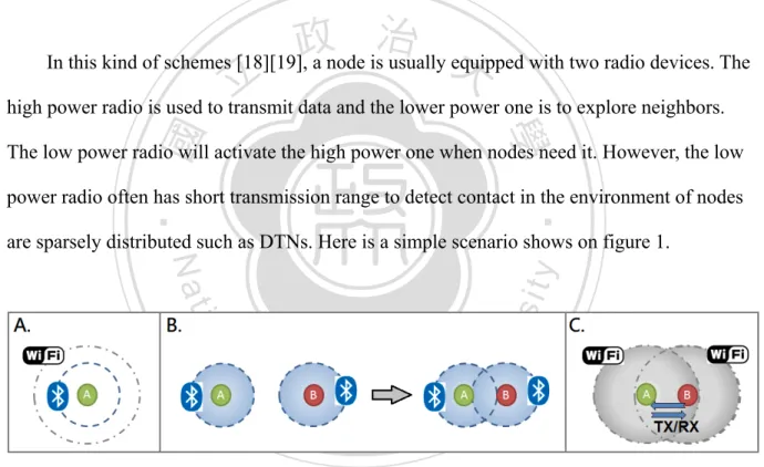
(19) 2.3.1 Scheduled Rendezvous In scheduled rendezvous schemes [16] [17], there is generally assumed that clock synchronization is exist. The predefined schedule can wake nodes up at the same moment. In the distributed environment as DTNs, it is hard to synchronize all nodes without inaccuracy. . 2.3.2 On-demand. 治 政 In this kind of schemes [18][19], a node is usually equipped 大 with two radio devices. The 立 high power radio is used to transmit data and the lower power one is to explore neighbors. . ‧ 國. 學. The low power radio will activate the high power one when nodes need it. However, the low. ‧. power radio often has short transmission range to detect contact in the environment of nodes are sparsely distributed such as DTNs. Here is a simple scenario shows on figure 1.. n. er. io. sit. y. Nat. al. Ch. engchi. i n U. v. Figure 1:On-demand wakeup scheduling. A.. Each node contains with both high power radio and lower power radio architectures. (e.g.WiFi and BlueTooth ). B.. All nodes are using lower power radio to explore neighbors.. 7 .
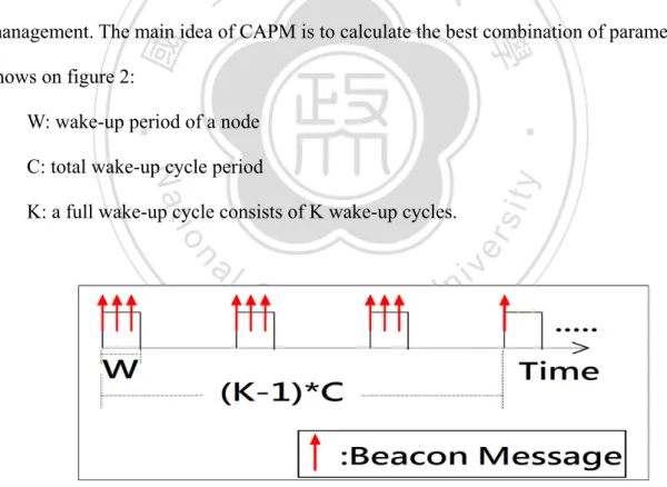
(20) C.. When a contact occurs, nodes are switching to high power radio to transmit and receive data.. 2.3.3 Asynchronous Asynchronous mechanisms do not require time synchronization [20] [21]. The trade-off is that system has to control the wakeup scheme carefully to make sure that nodes will be. 政 治 大 Management scheme, CAPM, to improve the PROPHET routing protocol for power 立 awake while a contact occurs. Yong Xi et al. [22] present the Context-Aware Power. ‧ 國. 學. management. The main idea of CAPM is to calculate the best combination of parameters shows on figure 2:. ‧. W: wake-up period of a node. sit. y. Nat. C: total wake-up cycle period. io. n. al. er. K: a full wake-up cycle consists of K wake-up cycles.. Ch. engchi. i n U. v. Figure 2:The tuple (W,C,K) as the sleep pattern in CAPM. 8 .
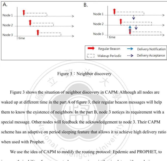
(21) 政 治 大. Figure 3:Neighbor discovery. 立. ‧ 國. 學. Figure 3 shows the situation of neighbor discovery in CAPM. Although all nodes are waked up at different time in the part A of figure 3, their regular beacon messages will help. ‧. them to know the existence of neighbors. In the part B, node 3 notices its requirement with a. sit. y. Nat. special message. Other nodes will feedback the acknowledgement to node 3. Their CAPM. io. when used with Prophet.. er. scheme has an adaptive on period sleeping feature that allows it to achieve high delivery ratio. al. n. v i n We use the idea of CAPM toCmodify U Epdemic and PROPHET, to h e nthegrouting c h i protocol:. improve their ability of energy control as comparisons in the simulator with our design.. 9 .
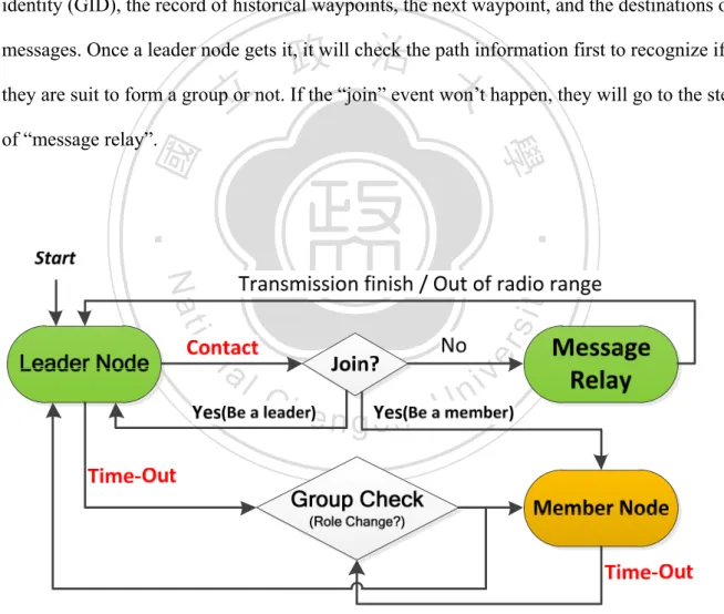
(22) CHAPTER 3 Energy-aware Grouping Design . 政 治 大 protocol and describe details in the subsections below. We purpose a location-assisted routing 立 In this section, we will introduce our design in detail. At first, we give an overview of the. ‧ 國. 學. with Energy-aware grouping design by considering moving pattern within two grouping methods to extend system lifetime.. ‧. Most wireless devices can operate in different modes to control the power consumption,. sit. y. Nat. such as idle listening, sleeping, transmitting, and receiving. The power consumption of idle. io. er. listening is the main target to reduce in wireless ad hoc networks for efficiency energy usage. al. [23]. Our main idea is to form groups where each group has only one node awake, called. n. v i n C h and messages’ transmission “leader node”, to charge with contacts in listening mode or engchi U. transmitting/receiving mode. And all the others in the same group, called “member nodes”, will turn the communication device to sleeping mode to save energy. The isolated node is also a leader node which is keeping awake. We also set a timed-out parameter for sleeping duration to prevent a node been dead-lock in the sleeping mode without role changing.. 10 .
(23) 3.1 System Model We model a DTN as a set of mobile nodes in a pedestrian environment. A node is a pedestrian who carries a mobile device equipped with GPS and 802.11 communication modules. A “contact” is defined as two nodes are within their 802.11 radio range so that they can exchange messages for the duration. Since member nodes turn to sleeping mode most. 政 治 大 A navigation system is preinstalled with map data in each node. Base on it, nodes can get 立. time, we limit a contact will only happen between two leader nodes.. ‧ 國. 學. the GPS information of both its moving route and messages’ destinations to packet in beacon message for contact broadcast. Each message has a fixed destination location such as a portal. ‧. to internet.. n. al. er. io. sit. y. Nat 3.2 Moving Pattern. Ch. . engchi. i n U. v. We assume that all nodes can only move on the roads. Each node has its own group which has been predefined such like school, job…etc. And we consider three kinds of nodes’ moving scenarios:. 1. Nodes never depart. 2. Nodes may depart or join. 3. Nodes move randomly.. 11 .
(24) 3.2.1 Scenario 1:Nodes Never Depart In this scenario, a group looks like a touring party in a tourist attraction. People have same moving path, speed, and stop duration. They will always move around their guide until the tour ended. We assume each node has an unique node identity and a group identity (GID) it belongs to. Each group is formed by default with a group table and an unique identity which. 政 治 大. is different to all other groups. Because of all nodes are moving with similar parameters, they. 立. will never depart from its group.. ‧ 國. 學. 3.2.2 Scenario 2:Nodes May Depart or Join. ‧ y. Nat. . io. sit. Same as the first scenario, groups are formed by default with group tables, but some. n. al. er. nodes might depart from the group because of different moving speed or path. When a node. Ch. i n U. v. leaves away, it won’t be found on leader selecting duration. After that, the group will keep. engchi. working with rest nodes and the isolated node will change to be a leader node itself. “Join” event will only happen between two leader nodes. When two leader nodes contact, they will try to negotiate if one of them join to another or not. If the join event happens, all other member nodes will turn to be leader nodes to charge with everything themselves.. 3.2.3 Scenario 3:Nodes Move Randomly In the last scenario, nodes are randomly moving with a group identity (GID). Like people 12 .
(25) work in same company or students study in same school, they will have a same GID. Similar to scenario 2, “Join” event will only happen between two leader nodes. If both of them are single node, the event can be also called “form a group” event. The different between 2 and 3 is nodes are along in the beginning. And “depart” and “join” events occur more often in this scenario.. 立. 政 治 大. ‧. ‧ 國. 學. n. er. io. sit. y. Nat. al. Ch. engchi. 13 . i n U. v.
(26) 3.3 Energy-aware Grouping (EG) Design . Figure 4 is an overview of our design: Energy-aware Grouping (EG). Since nodes. are equipped GPS device, a leader node will record the waypoints of its moving path which are predefined in the preinstall navigation system. A beacon message contains with its group identity (GID), the record of historical waypoints, the next waypoint, and the destinations of. 政 治 大 they are suit to form a group or not. If the “join” event won’t happen, they will go to the step 立 messages. Once a leader node gets it, it will check the path information first to recognize if. ‧. ‧ 國. 學. of “message relay”.. n. er. io. sit. y. Nat. al. Ch. engchi. i n U. v. Figure 4:Overview of Energy-aware Grouping (EG). 14 .
(27) . When the sleeping duration timed-out, all nodes are checking their status and. transmit a message of it to their leader node to make the decision of leader selection for next round. After the selection, the original leader node will alert all other nodes who will be the new leader node in next round. A member node goes to sleeping mode after received the alert and the new leader node charges with group’s contact and messages’ transmission.. 政 治 大. 3.3.1 Methods choose when contact between method 1 (M1) and method 2 (M2). 立. . Our design contains with two methods for different scenarios. The first method, called. ‧ 國. 學. . M1, is designed for less changing situation like scenario 1 and the other method, called M2, is. ‧. for others.. Nat. sit. y. A single node uses M2 as its default grouping policy for more opportunities to form a. n. al. and the record of historical and next waypoints.. Ch. engchi. er. io. group. When a contact occurs, leader nodes will check the other one’s group identity (GID). i n U. v. If they have a same GID and same waypoints in the last three (or more) waypoints, they will use M1 to form a group. This is also the only chance for a node to change its grouping method from M2 to M1. Once a node chooses M1, it will not change the group method until it becomes a group contains with only single node, such as the situation of can’t find its leader node after sleeping duration timed-out. Choosing M1 is the highest priority if the conditions are satisfied. When the conditions for M1 are dissatisfied, they will choose M2 as their grouping method if they have same records of next waypoints. Otherwise, they will go to message relay policy checking. 15 .
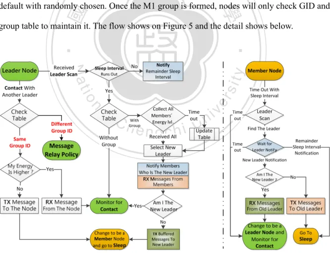
(28) 3.3.2 Method 1 (M1) for less variation When a group formed by M1 method, it will only check the group identity (GID) as the main condition any time. Even if a node has same moving path in the future approaches, it is not allowed to join the M1 group if its GID is not match. Each GID is an unique code with a. 政 治 大 grouping with and which one is the leader node of the group. The first leader node is set by 立 group table in the system. Every node has its group table to realize which node can be. ‧ 國. 學. default with randomly chosen. Once the M1 group is formed, nodes will only check GID and group table to maintain it. The flow shows on Figure 5 and the detail shows below.. ‧. n. er. io. sit. y. Nat. al. Ch. engchi. i n U. v. . Figure 5:The flow of method 1 (M1) 16 .
(29) At the beginning of the round, nodes check its group table to recognize its GID and the role of the group. If it is a member node, it broadcasts a beacon message contains with its GID and energy level. If it gets leader’s acknowledgement, it will wait the message contains with next leader node information until time-out. If it gets nothing but time-out, it will turn to be a leader node itself and change the grouping method to M2. On the other side, a leader node tries to collect all information of its group members until time-out. When it gets all. 政 治 大. information, it chooses a new leader which has the highest power in the whole group. Then it. 立. transmits a message to notify which one is the new leader node at next round to all member. ‧ 國. 學. messages but the new leader node. After all, member nodes turn to sleeping mode and the old leader exchange the buffered messages to new leader and then change its role to member node. ‧. and turn to sleeping mode.. n. er. io. sit. y. Nat. al. Ch. engchi. 17 . i n U. v.
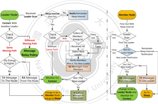
(30) 3.3.3 Method 2 (M2) for the environment with groups will change In order to be more flexible for nodes’ mobility, we purpose another method, called M2, to improve M1. A group contains with only leader node is setting to use M2 as its grouping method. Figure 6 is the flow of M2 and the detail shows below.. 立. 政 治 大. ‧. ‧ 國. 學. n. er. io. sit. y. Nat. al. Ch. engchi. i n U. v. Figure 6:The flow of method 2 (M2) The main concept of M2 which is different to M1 is the grouping policy. M1 uses GID to make the grouping decision. In the M2 method, nodes will check their future routing path. When they have same path in nearly future, they are allowed to form a M2 group. If they don’t, they will check only the message relay policy. The leader node’s selection of the group is still considering the energy level of nodes. The higher one will be the leader node and the 18 .
(31) other one will be the member node and then turns to sleeping mode after buffered messages have been exchanged. The sleeping interval of a node is calculating by itself. Since it can recognize the same path when grouping, it can estimate how much time will take to reach the location that is the end of the same path. When a member node wakes up and cannot find its leader node, it will change its role to be a leader node itself. The rest part of the design M2 is similar to the design in M1. A group has only one awake node, called leader node, to charge with messages’ transmission and others turn to sleeping mode.. 立. 政 治 大. ‧. ‧ 國. 學. n. er. io. sit. y. Nat. al. Ch. engchi. 19 . i n U. v.
(32) 3.4 Message Relay Policy In the contact duration, when and which message to transmit for relay nodes is an issue. Similar to forwarding-based routing protocol, we are using location information to make the decision of relay. Although the GPS module consumes more energy than updating a probability table of forwarding-based protocol at once, but the table should be update in a. 政 治 大 smaller than table updating computing. 立. short periodic to support high delivery ratio so that the total energy consumption of GPS are. ‧. ‧ 國. 學. As the Figure 7 shows below,. n. er. io. sit. y. Nat. al. Ch. engchi. i n U. v. Figure 7:Message Relay Policy. → : The direction from node A to its message m(a)’s destination. → : The direction from node B to its destination.. 20 .
(33) θ :The angle between → and → . When a leader node A contacts with a leader node B, their beacon message contains with their destination’s GPS information. Node A which has a message m(a) will calculate the angle θ between m(a)’s destination and node B’s destination. If the angle θ is less than the threshold, it means that node B is a good receiver for relay the message m(a) so that node A will transmit m(a) to node B.. 立. 政 治 大. ‧. ‧ 國. 學. n. er. io. sit. y. Nat. al. Ch. engchi. 21 . i n U. v.
(34) CHAPTER 4 Simulation and Results. 政 治 大. In this section, we describe parameters of simulation and analyze results between three. 立. protocols:. ‧ 國. 學. 1. Energy-aware Grouping Design, EG 2. Epidemic with CAPM [22], EpC. ‧. 3. PROPHET with CAPM [22], ProC. sit. y. Nat. We insert the idea of CAPM [22] as the energy saving scheme to both Epidemic and. io. al. er. PROPHET routing protocols for comparison. Both of them work in the energy limitation. n. environment are more efficiency and the system live longer than their original version in it. . Ch. i n U. engchi. v. The major object of DTNs routing protocol is to maximize delivery ratio on a rapidly changing topology. By considering energy, nodes’ lifetime is also an important issue to compare. We evaluate our design in four metrics: . Messages delivery ratio. . Nodes lifetime. . Overhead ratio =. . End-to-end delay. 22 .
(35) 4.1 Simulation Setup We use a map-based model of a small part of Helsinki for The ONE simulator (version 1.4.1). All nodes are pedestrian and can only move on the roads of the map. When a node reaches its destination, it will randomly choose a new location of the map as its next destination and move to there by shortest path algorithm. Figure 8 is a snap shot of a simulation.. 立. 政 治 大. ‧. ‧ 國. 學. n. er. io. sit. y. Nat. al. Ch. engchi. i n U. v. Figure 8:A snap shot of the ONE simulator.. 23 .
(36) 4.1.1 General Settings of Simulator The simulation time is 43200 seconds (12 hours). There is a warm up time for PROPHET set as 1000 seconds and all data will not count in evaluation during warm up period. The moving speed of nodes is 0.5 m/s to 1.5 m/s. The data transmission rate is 1 Mbps and the transmission range is 100m. The message size will randomly generate between 512 KB to 1 MB .Its generation interval is 5 seconds to 10 seconds and randomly chooses a node. 政 治 大 the map as its destination before generated. The buffer size is 250 MB in each node. Table 1 is 立 to own the message. The TTL is 5 hours. Each message randomly chooses a fixed location of. ‧. ‧ 國. 學. the parameters we described above.. n. er. io. sit. y. Nat. al. Ch. engchi. i n U. v. Table 1:Parameters of simulation setting 24 .
(37) 4.1.2 Parameters about Energy Consumption In order to close to the reality, we use 5 smart phones to measure the energy consumption of message transmission, GPS position, and probability computing. There are three kinds of brands: hTC Desire *3, Motorola DEFY*1, and Samsung Galaxy S*1. All of them are reset to factory default of Android v2.2 before tests. All tests are start with full power and the darkest backlight. In the GPS test, we put phones under a sunny day without moving. In the. 政 治 大 limitation from a PC server. In table 2 , all data are average from 20 tests of each phone. 立. transmission test, we download / upload a 1GB file nearby a WiFi router with 1Mbps speed. ‧. ‧ 國. 學. n. er. io. sit. y. Nat. al. Ch. i n U. v. Table 2:Parameters of energy consumption. engchi. 25 .
(38) 4.2 Simulation Results We will show two kinds of diagram: number of dead nodes with time line and delivery ratio with time line. Then show the summary of the end in the scenario. As the section 3.2, we evaluate our design in three different scenarios: 1. Nodes never depart. 2. Nodes may depart or join. 3. Nodes move randomly.. 立. 政 治 大. ‧ 國. 學. Our design gets the best performance in delivery ratio and overhead ratio. Number of nodes alive gets close to other schemes in random moving case but strength in others.. ‧. The number pair with hyphen in the diagram like “48-30” means there are 48 grouped. sit. y. Nat. nodes been randomly distributed in 9 groups and 30 isolated nodes at the start. The pair “0-78”. io. al. er. in scenario 3, nodes move randomly, means there is no group at the start but nodes still setup. n. a group identity for our scheme.. Ch. engchi. i n U. v. 4.2.1 Nodes Never Depart In this scenario, groups are formed when start. All nodes will never leave the radio range of their leader node like a tourist group with a guide.. 26 .
(39) 立. 政 治 大. ‧. ‧ 國. 學. Figure 9:Number of dead nodes in scenario 1 (Nodes never depart).. sit. y. Nat. io. er. Figure 9 shows the number of dead nodes with time line. Because of groups never split,. al. each node of a group will collect all of messages’ copies from all other nodes in the same. n. v i n group with Epidemic routing andC PROPHET h e n grouting. c h i ItUmakes all nodes in groups die quickly and cause entire group disappear. Although both of them are modified with energy saving scheme, this behavior cost lots of resource but less contribution for messages delivery.. 27 .
(40) 立. 政 治 大. ‧. ‧ 國. 學. Figure 10:Delivery ratio in scenario 1 (Nodes never depart).. sit. y. Nat. io. er. Figure 10 shows the delivery ratio in scenario 1 with time line. As figure 6 shows above,. al. dead nodes increase fast during 10000sec~20000sec. It makes Epidemic and PROPHET. n. v i n C ha message to a relayUnode or the destination. Although schemes are easy to fail for delivery engchi the ratio of our design increases slowly at the beginning, , the extension of nodes’ lifetime makes the ratio can stably hold on a high level.. 28 .
(41) 政 治 大. 立. ‧. ‧ 國. 學. Table 3:Summary of the end in Scenario 1 (Without nodes depart from groups). The summary of the end shows in table 3. Our design has the best performance of. Nat. sit. y. delivery ratio, overhead ratio, and the number of nodes alive. All entries above are double. n. al. er. io. higher than other schemes at least.. i n U. v. Figure 11 and figure 12 show the effect with different pairs of grouped-isolated nodes.. Ch. engchi. For 30-30 vs. 48-30, more grouped nodes in a group will create more messages for delivering. It means a leader node needs to exchange more packets when role changing and a contact between leader nodes. A group with more nodes does not clearly increase its performance or lifetime. For 48-12 vs. 48-30, less isolate nodes do reduce the delivery ratio of the system.. 29 .
(42) 立. 政 治 大. ‧ 國. 學. Figure 11:Number of dead nodes with different pair in scenario 1. ‧. n. er. io. sit. y. Nat. al. Ch. engchi. i n U. v. Figure 12:Delivery ratio with different pair in scenario 1 30 .
(43) 4.2.2 Nodes May Depart or Join A group formed by M1 method in this scenario is similar to it in the first one, but some nodes will depart from it and allow them to rejoin when come back. In the other hand, any two leader nodes may form a group by M2 method during their same path in the nearly future.. 立. 政 治 大. ‧. ‧ 國. 學. n. er. io. sit. y. Nat. al. Ch. engchi. i n U. v. Figure 13:Number of dead nodes in scenario 2 (Nodes may depart).. Figure 13 shows the number of dead nodes with time line in scenario 2. The curves of Epidemic and PROPHET are similar to them in scenario 1. Because of some nodes will depart from its group, the effect is much bigger to our design. The departing nodes have less energy saving if they can’t meet someone to form a M2 group. Therefore they will die much quick than they in scenario 1 with M1 group.. 31 .
(44) 立. 政 治 大. ‧. ‧ 國. 學. Figure 14:Delivery ratio in scenario 2 (Nodes may depart).. sit. y. Nat. io. er. Figure 14 shows the delivery ratio in scenario 2. It has almost the same curves in. al. scenario 1. But the increasing dead nodes affect our performance at the final part. Departing. n. v i n C hdelivering messagesUfor entire system. But when they nodes may create more chances for engchi rejoin the M1 group, they also make the buffered messages highly increase to a group. A leader node has to cache and transmits more messages when contact and leader buffer. exchange than it in scenario 1. It highly decreases the lifetime of a group and then reduces the overall efficiency of the system.. 32 .
(45) 立. 政 治 大. ‧ 國. 學. Table 4:Summary of the end in Scenario 2 (Nodes may depart).. ‧ sit. y. Nat. The summary of the end in scenario 2 shows in table 4. Our design also has the best. io. al. er. performance of delivery ratio, overhead ratio, and the number of nodes alive. Because of. n. nodes might depart, the M1 method will get less advantage than it in scenario 1. But the M2. Ch. method can make some subsidies for energy saving. . engchi. i n U. v. Figure 15 and figure 16 show the effect with different pairs of grouped-isolated nodes.. For 30-30 vs. 48-30, as we discuss above that rejoin a departed node increase the loading for a group and more grouped nodes increase the kind of chance. Less total number of nodes will generate less delivery request so that the delivery ratio in 30-30 will decrease slowly. For 48-12 vs. 48-30, less isolate nodes also affect the delivery ratio of the system. . 33 .
(46) 立. 政 治 大. ‧ 國. 學. Figure 15:Number of dead nodes with different pair in scenario 2. ‧. n. er. io. sit. y. Nat. al. Ch. engchi. i n U. v. Figure 16:Delivery ratio with different pair in scenario 2 34 .
(47) 4.2.3 Nodes Move Randomly With all nodes move randomly, this is an extreme case for our design. The M1 method is almost failed to work here. A leader node is difficult to meet another one with the way which is long enough to satisfy the conditions of M1 group forming. Nodes can only work with M2 method all the time.. 立. 政 治 大. ‧. ‧ 國. 學. n. er. io. sit. y. Nat. al. Ch. engchi. i n U. v. Figure 17:Number of dead nodes in scenario 3 (Nodes move randomly).. Figure 17 shows the number of dead nodes in scenario 3 (Nodes move randomly). With the M2 method, a group is rapidly changing so that the effect of energy saving is limited. Before 52 nodes have been dead, our design is more efficient for energy saving than Epidemic with high message duplication and PROPHET with high information computing. After that,. 35 .
(48) nodes are too sparely distributed to reduce the opportunist of a contact. It mitigates energy consumption for message relay especially in Epidemic.. 立. 政 治 大. ‧. ‧ 國. 學 er. io. sit. y. Nat. al. v. n. Figure 18:Delivery ratio in scenario 3 (Nodes move randomly).. Ch. engchi. i n U. Figure 18 shows the delivery ratio in scenario 3 (Nodes move randomly). Although this extreme scenario attacks the weakness in energy saving of our design, we can still make good delivery ratio in the relatively high level. Because of lower M1 groups, there are less dangerous situations of destroying M1 groups in scenario 2 and also make the curve much better than it in scenario 2.. 36 .
(49) 立. 政 治 大. ‧ 國. 學. Table 5:Summary of the end in Scenario 3 (Nodes move randomly).. ‧ sit. y. Nat. The summary of the end in scenario 3 shows in table 5.Our design still has good. io. er. performance of delivery ratio and overhead ratio. Although we are using GPS information. al. which cost much energy for simple computing to make decisions, the table shows the benefit. n. v i n C h Nodes with highUcomputing to maintain delivery ratio of lower computing to node’s lifetime. engchi such as PROPHET routing protocol, makes nodes die quickly and then affect its delivery ratio.. 37 .
(50) CHAPTER 5 Conclusions and Future Work. 5.1 Conclusion . 立. 政 治 大. We propose two designs M1, M2 with lower redundancy copies and lower information. ‧ 國. 學. computing but good delivery ratio in energy limitation environment. The M1 design works. ‧. well in “no depart” environment. The M2 design is more suitable for rapidly changing environment even if there is no group。. y. Nat. io. sit. Considering the moving pattern of people, our designs are more suitable for real-life. n. al. er. implementation. Our designs make number of nodes alive 3 times more than others in the environment with groups.. Ch. engchi. i n U. v. 5.2 Future Work In this thesis, our main idea is left only one node alive for a group. There are many of energy saving designs for one single node in DTNs. We will try to combine two or more energy saving design to enhance our design to make it be more suitable for randomly moving scenario or other complex, unpredictable scenarios in DTNs.. 38 .
(51) References [1] Jian Shen, Sangman Moh, Ilyong Chung, “Routing Protocols in Delay Tolerant Networks: A Comparative Survey”, The 23rd International Technical Conference on Circuits/Systems,Computers and Communications, pp. 1577 - 1580, 8 July, 2008 [2] E.P.C. Jones and P.A.S ward, “Routing Strategies for Delay-Tolerant Networks”, Submitted to Computer Communacation Review,2008. 學. ‧ 國. [3]. 政 治 大 T.Armstrong, “Wake-up Based Power Management in Multihop Wireless Networks”, 立 Term Survey Paper, University of Toronto.. [4] VAHDAT, A., AND BECKER, D. “Epidemic routing for partially connected ad hoc networks”, Technical Report CS-200006, Duke University, April 2000.. ‧. er. io. sit. y. Nat. [5] R. H. Frenkiel, B. R. Badrinath, J. Borres, and R. D. Yates, “The infostations challenge: balancing cost and ubiquity in delivering wireless data”, IEEE Personal Communications, vol. 7, no. 2, pp. 66–71, 2000 [6] J. Lebrun, C.-N. Chuah, D. Ghosal, and M. Zhang, “Knowledge-based opportunistic forwarding in vehicular wireless ad hoc networks”, in Proceedings of IEEE Vehicular Technology Conference (VTC), vol. 4, pp. 2289–2293, May 2005.. n. al. Ch. engchi. i n U. v. [7] A. Lindgren, A. Doria, and O. Schelen, “Probabilistic routing in intermittently connected networks”, in Proc. First International Workshop on Service Assurance with Partial and Intermittent Resources, pp. 239––254,2004. [8] H. Dang and H. Wu, “Clustering and Cluster-Based Routing Protocol for Delay-Tolerant Mobile Networks”, IEEE Transactions on Wireless Communications, Vol. 9, No.6, pp.1874–1881, June 2010. [9] P. Hui, A. Chaintreau, J. Scott, R. Gass, J. Crowcroft, and C. Diot, “Pocket switched networks and human mobility in conference environments”, in Proc. ACM SIGCOMM Workshop on DTN and Related Topics, pp. 244––251, 2005.. 39 .
(52) [10] T. Spyropoulos, K. Psounis, and C. S. Raghavendra, “Spray and wait: an efficient routing design for intermittently connected mobile networks”, in Proc. ACM SIGCOMM Workshop on DTN and Related Topics,pp. 252––259, 2005. [11] C. Liu and J. Wu, “Scalable routing in delay tolerant networks”, in Proc.ACM MobiHoc, 2007. [12] A. Chaintreau, P. Hui, J. Crowcroft, C. Diot, R. Gass, and J. Scott, “Impact of human mobility on the design of opportunistic forwarding algorithms”, in Proc. IEEE INFOCOM, pp. 1––13, 2006.. 政 治 大. [13] M. Kim, D. Kotz, and S. Kim, “Extracting a mobility model from real user traces”, in Proc. IEEE INFOCOM, pp. 1––13, 2006.. 立. ‧. ‧ 國. 學. [14] T. Spyropoulos, K. Psounis, and C. Raghavendra, “Performance analysis of mobility-assisted routing”, in Proc. MobiHoc’06: 7th ACM International Symposium on Mobile Ad Hoc Networking and Computing,pp. 49––60, 2006.. sit. y. Nat. [15] J. Leguay, T. Friedman, and V. Conan, “DTN routing in a mobility pattern space”, in Proc. WDTN‘05: 2005 ACM SIGCOMM Workshop on Delay-tolerant Networking, pp. 276––283, 2005.. n. al. er. io. [16] B. Chen, K. Jamieson, H. Balakrishnan, and R. Morris, “Span: An energy-efficient coordination algorithm for topology maintenance in ad hoc wireless networks”. In Proceedings of the 7th ACM International Conference on Mobile Computing and Networking, pages 85–96, Rome, Italy, July 2001. Ch. engchi. i n U. v. [17] B.Awerbuch, D.Holmer and H. Rubens, “The Pulse Protocol: Energy Efficient Infrastructure Access”, IEEE INFOCOM, 2004 [18] E. Shih, P. Bahl, M. J. Sincalir, “Wake on wireless: An event driven energy saving strategy for battery operated devices“, Proceedings of ACM Mobicom, 2002. [19] M. J. Miller, N. H. Vaidya, ”Power save mechanisms for multihop wireless networks, Proceedings of 1st International Conference on Broadband Networks”, 2004. [20] R. Zheng, J. Hou, and L. Shab, “Asynchronous wakeup for ad hoc networks”. The Fourth ACM International Symposium on Mobile Ad Hoc Networking and Computing (MobiHoc 03), January 2003 40 .
(53) [21] Tseng, Y.-C., Hsu, C.-S., Hsieh, T.-Y., “Power-saving protocols for IEEE 802.11-based multi-hop ad hoc networks ,” Journal of Computer and Telecommunications Networking, Vol.43, No.3, pp.317-337, 2003. [22] Yong Xi , M. Chuah , K. Chang, “Performance evaluation of a power management scheme for disruption tolerant network”, Mobile Networks and Applications, v.12 n.5, p.370-380, December 2007 [23] L. M. Feeney and M. Nilsson, “Investigating the energy consumption of a wireless network interface in an ad hoc network”, In INFOCOM, 2001.. 政 治 大. [24] Ari Keränen, Jörg Ott, Teemu Kärkkäinen, “The ONE Simulator for DTN Protocol Evaluation”, in SIMUTools’09: 2nd International Conference on Simulation Tools ans Techniques, Rome, March 2-6,2009. 立. ‧. ‧ 國. 學. n. er. io. sit. y. Nat. al. Ch. engchi. 41 . i n U. v.
(54)
數據

+7


相關文件
In basic education, students acquire a foundation of knowledge, skills and values across Key Learning Areas. They also receive guidance and advice to help them make
an insider, trades or procures other persons to trade in the securities or derivatives of the company so as to make profits or avoid losses before the public are aware of
People need high level critical thinking skill to receive and deconstruct media messages and information from different sources.
• You can make good use of this opportunity and become more aware of the importance of teaching information texts with an explicit emphasis on understanding the features of academic
• A formal usage policy and procedures should be in place, and appropriate security measures should be adopted to protect against the risks of using mobile computing and
Data from the 1000 Genomes Project will be made available quickly to the worldwide scientific community through freely accessible public databases... 幕後英雄
• Instead of uploading and downloading the dat a from cloud to client for computing , we shou ld directly computing on the cloud ( public syst em ) to save data transferring time.
and/or make predictions about the future behaviour of a system in the real world. ● requires the modeller to be creative and make choices, assumptions,
