2001 Springer-Verlag London Limited
A BOM Oriented Class-Based Storage Assignment in an
Automated Storage/Retrieval System
S. Hsieh and K.-C. Tsai
National Taiwan University, Taipei, 10764 Taiwan
A storage assignment policy based on the needs of manufactur-ing operations can increase not only the performance of the automated storage/retrieval system (AS/RS) but also the per-formance of the production system. In general, the needs of manufacturing operations are embedded in material attributes, and the bill of material (BOM) is the best source to link material attributes. By employing the BOM as the backbone structure of a production system, a CIM system can be thor-oughly integrated. Past work has identified a class-based assignment method for an AS/RS as a reasonable and efficient storage assignment policy. This study presents a BOM oriented class-based storage assignment method for an AS/RS. The proposed method possesses not only the advantage of a class-based storage method, but also the feasibility to integrate an AS/RS into a CIM system. To illustrate the effectiveness of the proposed method, a case study is presented. A random storage assignment method is also employed to obtain the solution for the illustrative example. The results are used to compare with those obtained by the proposed method. From the results of comparative studies, the proposed BOM-oriented class-based AS/RS assignment method is shown to be efficient.
Keywords: Automated storage/retrieval systems; Bill of materials; Material attributes; Storage assignment method
1. Introduction
An automated storage/retrieval system (AS/RS) offers the bene-fits of improved inventory management, space efficiency, reduced labour costs, and reduced costs of loss by theft. Thus, the employment of an AS/RS can dramatically improve the efficiency of material handling and inventory control. Hausman et al. [1] stated that the maximum benefits of such a system depend upon the optimal warehouse design and the optimal scheduling of pallet assignment, storage assignment, and
Correspondence and offprint requests to: S. Hsieh, Department
of Mechanical Engineering, National Taiwan University, No. 1 Roosevelt Road, Sec. 4, Taipei, 10764 Taiwan. E-mail: shhsieh얀w3.me.ntu.edu.tw
interleaving. Work on improving an AS/RS has attracted much attention in recent years. Linn and Wysk [2] presented an expert-system-based AS/RS controller, ECSSIM, to search for storage location, retrieval location, restoring policy, and job sequencing in a queue and between queues. Egbelu [3] mini-mises the service response time in an AS/RS by selecting the dwell point of the storage/retrieval machine. Sarker and Babu [4] presented a review and a comparative study of some design aspects of AS/RSs with special emphasis on travel time models. Randhawa and Shroff [5] investigated the effect of the system configuration and policies used for storing and retrieving items to and from the warehouse via simulation studies. Pan and Wang [6] constructed a dual-command-cycle continuous-travel-time model using a class-based assignment. Larson et al. [7] presented a three-phase procedure for warehouse layout con-figuration based upon class-based storage principles.
In spite of the differences in hardware structure, the storage bay assignment policy is still one of the most effective means of enhancing system performance and operational efficiency in a warehouse. Heskett [8] presented a cube-per-order index (COI) policy as the basis for a storage assignment. Hausman et al. [1] compared the efficiency of three different storage rules including random storage assignment, full turnover-based assignment, and class-based turnover assignment. Graves et al. [9] pointed out that the balance between the enhancement of S/R efficiency and the best use of storage capacity can be achieved by employing interleaving systems and the class-based turnover assignment rule to assign the storage area. Rosenblatt and Eynan [10] developed a 1D class-based storage assignment search procedure to obtain the optimal boundaries for determining the best storage area based upon appropriate class-based demand. Eynan and Rosenblatt [11] presented a 1D search procedure for dividing single-command rectangular warehouses into classes. Muralidharan et al. [12] proposed a new shuffling heuristic-based approach that combines the ran-dom storage and class-based storage assignments for AS/RS storage assignment. Mansuri [13] presented a computerised algorithm to investigate dedicated storage allocation alternatives for AS/RSs. Thonemann and Brandeau [14] applied the turn-over-based and class-based assignment policies to a stochas-tic environment.
data model for material requirements planning (MRP) systems design. Koulamas [18] developed an efficient search technique by using the powers of the BOM matrix and a tool data matrix to increase (decrease) the tool requirements resulting from a decrease (increase) in an end product completion time. Hastings and Yeh [19] have highlighted advantages and proposed a structure to integrate BOM and production routeing. Trappey et al. [20] presented an object-oriented BOM (OOBOM) system as the core system for product management. The integration of manufacturing systems under a BOM structure is a preferred approach. Hence, an effective class-based AS/RS assignment policy expressed in terms of material attributes and a BOM structure is desired.
In view of the above, this study proposes a new approach, an BOM-oriented class-based storage assignment system, for enhancing the operational efficiency of an AS/RS, as well as a CIM system. By employing the proposed storage assignment method, a given specific type of material can be assigned easily to the most suitable bay in the AS/RS with optimised operational efficiency. The AS/RS so constructed and operated by the proposed policy, can respond quickly enough to the many functional calls required by other subsystems in a CIM-based production system. Hence, the integration of the AS/RS into the CIM environment becomes feasible.
2. BOM Oriented Class-Based Storage
Assignment
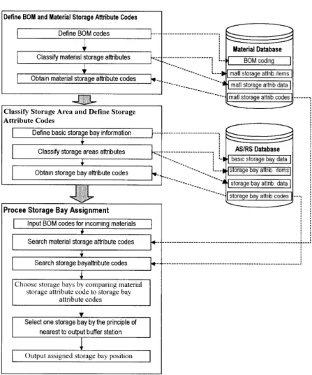
Since material properties are somewhat different from each other, the BOM oriented class-based storage assignment (BOM-class) method can be developed only in sequence in three consecutive steps. These steps are:
1. To define BOM and material storage attribute codes for each product.
2. To classify the storage area of the AS/RS and obtain a storage attribute code for each bay.
3. To process the storage bay assignment.
The schematic flow diagram for constructing a storage assignment using the BOM-class method is shown in Fig. 1.
2.1 To Define BOM and Material Attribute Codes
To construct a database sufficient for storing various materials for an AS/RS, some key information is generally required. This includes:
3. Functions of the part. 4. Source or status of the part.
5. The level of the part in a BOM structure. 6. Part identification number in a level.
7. The number of the revision version for the part drawing. Figure 2 shows a simple example of such a BOM code.
2.1.2 Classifying Material Storage Attributes
Based upon the degree of significance of each attribute for storage assignment, the storage attributes are roughly classified into two categories that include absolute attribute items and non-absolute attribute items.
In the process of assigning storage bays to a given set of materials, some of the storage attribute items of the materials have first to be checked carefully. If these attribute items are invalid, the material will not be allowed to enter the storage. This type of attribute items is generally referred to as absolute attribute items. Whenever the assignment of a storage bay is based upon the absolute attribute items, the decision for material entry to the storage bay is either yes or no.
In the process of assigning storage bays to a given set of materials, some of the storage attribute items of the materials are not coincident with the storage bay attributes. They may still be stored in the bay if there is not a more suitable bay. This may result in the possible extension of S/R time or reduction of operational efficiency. This type of attribute item is generally referred to as a non-absolute attribute item.
2.1.3 Coding of Material Storage Attributes
To avoid a large amount of textual data in the information flow, it is more convenient to use numbers and/or letters to represent the detailed literal material attribute records. By entering material storage attribute data in the computer, the material storage attribute can then be represented by an alphabetic/numerical code sequence. This code is also designed to interface with the BOM code for integrity and integration purposes. Figure 3 shows the structure and coding sequence of the material storage-attribute data items.
Although the material attributes of different manufacturing systems are somewhat different, the code sequence and the contents of the materials storage attributes for a specific manu-facturing system should be the same, with a uniform data format. The significance of each digit in the code will have to be addressed unambiguously. The determination of the align-ment sequence in each individual absolute and/or non-absolute digit is critical. The most common practice is to align the
Fig. 1. The BOM oriented class-based storage assignment method.
Fig. 2. The BOM coding items.
most significant digit to the left and the least significant digit to the right to reflect the significance of each digit in meeting all storage function requirements. As the codes for material storage attributes are delivered to the warehousing department, these should be able to be decoded for information extraction. Therefore, the establishment of a coding format is of great importance.
Once the BOM code, the material storage-attribute items, and the associated storage-attribute code for various materials are established, a CIM based material database becomes avail-able for the operations of an AS/RS.
Fig. 3. The structure and coding sequence of material storage-attribute items.
2.2 Classifying Storage Areas and Defining Storage Attribute Codes
Since there are numerous factors that will affect the entry of materials into the AS/RS, each storage bay can be assigned to several effective attributes in various possible classifications of storage areas. For example, Fig. 4 shows the relation between the classification of storage areas and the attributes of storage bays. The attributes of storage bay 7 include the first attribute data B, the second attribute data D, and the third attribute data E.
To construct the AS/RS database for storage, some infor-mation is required which should include the following modules: 1. Basic storage bay information.
2. Storage bay attribute classification. 3. Storage bay attribute codes.
2.2.1 Basic Storage Bays Information
An AS/RS database must comprise all the basic information needed for the storage bays:
1. Storage bay number. Each storage bay is given a specific identity number. This identity number is an identification number convenient for data communication.
2. Storage bay location. This information records each storage bay location in the AS/RS. The location of each bay is recorded by rack, column and row numbers.
2.2.2 Classification of Storage Bay Attributes
In the process of assigning storage bays to materials, the material storage-attribute items are divided into two categor-ies – absolute and non-absolute attributes items. The storage-bay attribute items of AS/RSs are also divided into these two categories. The procedure for classifying storage area must be established.
2.2.3 Relevant Factors Associated with Attributes
1. Relevant factors associated with absolute attributes. The storage can be classified into several different types, based upon the differences in hardware structure (unit-load, mini-load, man-on-board, etc.) and the type of materials to be stored (special shape of materials, frozen food, toxicant material, etc.). To use the storage effectively, it is necessary to fully understand the material storage-attributes that affect the structure of the storage. For example, a unit load type is suitable for storing material with attribute data such as large volume or mechanical parts, whereas the mini-load type is for materials with attribute data such as very small volume, large variety, or electronic parts. We refer to these attributes as absolute attributes in this paper. Table 1 gives several different types of storage, and the associated materials to be stored therein.
2. Relevant factors associated with non-absolute attributes. The storage can be further classified into smaller attribute groups so that the materials can be delivered to the correct
materials stored in very high or low temperature, etc.
storage bays. The storage areas can be classified according to the following principles:
(a) Manufacturing-process attributes. To classify the stor-age areas by the manufacturing process attribute. The materials ready to be processed by the same machine can be stored in the same storage area.
(b) Function attributes. To classify the storage areas by the material function. For example, bearings can be stored in one area, and gears can be stored in another area.
(c) S/R-frequency attributes. To classify the storage areas by S/R frequency. Some of materials such as common parts that usually have higher S/R frequency should be stored in areas near the input/output buffer station so that the S/R efficiency can be enhanced. The storage areas have be classified into A, B and C classes based upon the demand ABC curve [1].
(d) Physical location attributes. To classify the storage areas with the physical location. The materials ready to be manufactured should be stored in the area near the output station of the location of the next pro-cessing equipment.
(3) Quality control attributes. To classify the storage areas for material that is ready to be inspected, has been inspected and passed, or has been inspected and not passed.
2.2.4 Classification of Storage Areas
The procedure for classifying storage areas includes:
1. To determine key storage attribute items for the classi-fication of the storage areas. Assume Ntotal is the total
number of storage bays. {A, B, %, X} is the set of attribute items that significantly affects the classification of storage areas.
2. To classify storage attribute data types with respect to attribute items one by one. For instance, if attribute item A has N data types {A1, A2, A3, %, AN}, the AS/RS can be classified into N storage areas.
3. To determine the size (the number of bays) of the storage area for each attribute data type. The average quantity of materials that should be stored in data type 1 to N storage areas is {n1, n2, n3, %, nN}, respectively. The total quantity
of all materials is M=⌺N
i=1ni. The proportion of each data
type for an attribute item is
再
n1 M, n2 M, n3 M, %, nN M冎
Therefore, the number of storage bays that are assigned to attribute data types {A1, A2, A3, %, AN} are N1, N2, N3, %,
NN, respectively, where Ni = Ntotal × (ni/M), i is a positive integer and not greater than N.
4. To assign the storage attribute data type to each of the storage bays in the AS/RS.
5. To go to step 2 to process another storage attribute item.
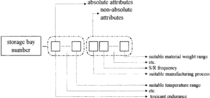
2.2.5 Coding of Storage Bay Attributes
The structure and coding sequence of the material storage attribute data items are given in Fig. 5. Based upon the assignment sequence and the code in each attribute item, the attribute code system of storage bays can also be constructed. Once the bay attribute items and the associated storage-bay attribute data are established, a CIM based AS/RS database becomes available for the operations of an AS/RS.
2.3 Processing of Storage Bay Assignment
The procedure for processing storage bay assignment involves the following steps:
1. To input BOM codes for incoming materials. 2. To search for the material storage-attribute code.
3. To search for the storage-bay attribute codes of the avail-able bays.
4. To choose storage bays by comparing the storage-bay attri-bute codes of the available bays with the given material storage-attribute and selecting the ones that fit best. 5. To select only one of the storage bays that were chosen in
step 4 by the principle of nearest to the output buffer station for the next process.
6. To output the assigned storage bay position by rack, column, and row number.
The process of bay selection can be divided into three portions, the selection of the storage type, the storage area, and the storage bay.
Fig. 5. The structure and coding sequence of the storage-bay attri-bute items.
1. The selection of the storage type is determined by the absolute attribute items. The computer will search for stor-age bays that have identical storstor-age-bay attribute data in the absolute attribute items, as has the incoming material. 2. Once the selection of the storage type is identified, the next
step is to check the code with the values of non-absolute attribute items in the second half section. The principle of comparison for non-absolute attribute items is based upon the level of compatibility. The attribute codes do not have to match exactly. The bays that have the highest compati-bility for non-absolute attribute items are selected. If, after the scanning and matching of the code data with the values of non-absolute attribute items, there are no storage bays with higher compatibility among all the bays, the storage bays selected earlier, based upon the absolute attribute data, will be used as the final decision on storage bay assignment. 3. The final selection of an appropriate storage bay is based upon the simple principle that the first priority available storage bay nearest to the output buffer station of the next process will be considered for material storage.
3. Implementation and Simulation Study
In order to illustrate the effectiveness of the proposed BOM-class method and to investigate the difference of performance competency compared with the random assignment policy, the operation system for grinding-wheel shaft production is selected as an example for the simulation study.
Jing Incorporated is a well-known company in the Taiwan machine tool industry for producing both conventional internal cylindrical grinding machines and CNC internal cylindrical machines. The spindle of the grinding wheel is a key compo-nent of a grinding machine. Grinding machines are equipped with several grinding-wheel spindles of different sizes. Two spindles of different sizes are usually provided with a grinding machine for use in different application speed ranges. This study takes the manufacture of the two different sizes of grinding-wheel spindles as an example. These two types of spindles are:
1. An extended grinding-wheel spindle for a rotating speed in the range of 30 000 r.p.m.
2. An extended grinding-wheel spindle for a rotating speed in the range of 50 000 r.p.m.
Figure 6 shows the plant layout and the relative location of the various manufacturing areas in the AS/RS zone. The spe-cific area that is used to produce the grinding-wheel spindle is also given in the figure. Some basic assumptions concerning the factory facility, the specifications, and the operation con-ditions of the AS/RS are given as follows:
1. The materials are moved immediately once they are retrieved from the AS/RS.
2. The AS/RS has one aisle with two input/output buffer stations on each end of the aisle. Two storage racks are located on both sides of the aisle. Each rack has ten columns and five rows. Thus, the AS/RS has 100 storage bays in
Fig. 6. The plant layout.
total. Unit load pallets are used as the means for moving material.
3. The size of each storage bay is assumed to be the same. 4. When the material is delivered to the storage bay or the
input/output buffer station by the S/R machine, the time required to load/unload the pallets is assumed to be negli-gible.
5. The AS/RS can only perform a single command task. 6. Once the S/R machine completes a task, the S/R machine
will remain at that position until the next command is issued. 7. Each input/output buffer station can be used to input/output material. These input/output buffer stations are located at both ends of the aisle on the bottom level.
8. The job arrival frequency and relevant attribute data are given.
In this example, we use Microsoft Access to establish both the databases for materials and the AS/RS. Microsoft Visual Basic is then used to implement the simulation program for two different systems, one is the proposed system and the other is a random storage system.
3.1 Defining the Codes of BOM and Material Storage Attributes
Figure 2 shows the structure of the BOM that includes the following items:
1. End item: 1digit, “1” represents an internal cylindrical grinder and “2” represents a CNC internal cylindrical grind-er.
2. Subassembly item: 2 digits, including bed subassembly, spindle subassembly, grinding-wheel shaft subassembly, etc. “09” is assigned to the grinding-wheel shaft subassembly in this example.
3. Function of the part: 2 characters, “3L” represents a rotating speed in the range of 30 000 r.p.m. and “5L” represents 50 000 r.p.m. in this example.
4. Source or status of the part: 1 character, “F” represents finished goods, “S” represents subassembly, “P” represents components, “C” represents common parts, “B” represents
cylindrical grinding-wheel shaft. It is the fourth part in level 2 of the BOM structure. The part drawing version is 0. The BOM code of the part is thus 1095L-2040.
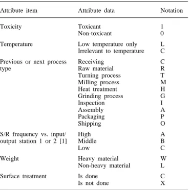
Once the BOM code is established, the material storage-attribute code is established with the structure shown in Fig. 3. There are 8 digits. The first two digits represent absolute attribute items: digit 1 is material toxicity and digit 2 is suitable temperature. The next six digits represent non-absolute attribute items: digit 3 (or 4) is the previous (or next) process type, digit 5 (or 6) is the S/R frequency vs. input/output buffer station 1 (or 2) [1], digit 7 is material weight and digit 8 is surface treatment. The code is explained in Table 2. If part 1093L-P2070 has material storage-attribute code 0CGACBLC, the record of the part stored in the material database is 1093L-P2070-0CGACBLC.
3.2 Classifying Storage Areas and Defining Codes of Storage Attributes
There are 100 bays in the AS/RS. For identification purposes, we give each bay a two-digit number from 00 to 99. The Table 2. Notation used in representing the material storage-attribute items and data.
Attribute item Attribute data Notation
Toxicity Toxicant 1
Non-toxicant 0
Temperature Low temperature only L Irrelevant to temperature C Previous or next process Receiving C
type Raw material R
Turning process T Milling process M Heat treatment H Grinding process G Inspection I Assembly A Packaging P Shipping O
S/R frequency vs. input/ High A
output station 1 or 2 [1] Middle B
Low C
Weight Heavy material W
Non-heavy material L
Surface treatment Is done C
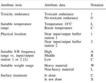
physical position of each bay is also recorded by rack, column, and row number, and can be obtained from the AS/RS database through a bay identification number. The structure and coding sequence of the storage-bay attribute is illustrated in Fig. 5. There are 8 digits. The first two digits represent absolute attribute items: digit 1 is toxicant endurance and digit 2 is suitable temperature range. The next six digits represent non-absolute attribute items: digits 3 ( or 4) are the physical location convenient for storing certain material that requires its input (or output) buffer station to be near, digit 5 (or 6) is the S/R frequency vs. input/output buffer station 1 (or 2) [1], digit 7 is suitable material weight range and digit 8 is surface treatment. The item data are shown in Table 3. Most of the storage-bay attribute items are the same as those of material storage-attribute items except that digits 3 and 4 – physical location – are different. However, there must be some connec-tion between them. A bay that is near to input/output buffer station 1 is suitable for storing a workpart which is just finished or is ready for turning, milling, or grinding. Thus notation “1” in digits 3 or 4 of the storage-bay attributes matches notation “T”, “M”, and “G” in digits 3 or 4 of the material storage-attributes. A bay that is near to the input/output buffer station 2 is suitable for storing a workpart which is just finished or ready for assembly, inspection, packing, or shipping. Thus notation “2” in digits 3 or 4 of storage-bay attributes matches notation “A”, “I”, “P”, and “O” in digits 3 or 4 of material storage-attributes.
3.3 Processing of Storage Bay Assignments
Once the material and AS/RS databases are established, the BOM code, the material storage-attribute code, and the AS/RS storage-bay attribute code can be obtained easily. The infor-mation can then be used to establish the BOM-class by compar-ing the bay attribute code and the material storage-attribute code and selecting the best-fit bay for storing the material. Next, we write a simulation program to generate the Table 3. Notations used in representing the AS/RS storage-bay attribute items and data.
Attribute item Attribute data Notation Toxicity endurance Toxicant endurance 1
No-toxicant endurance 0 Suitable temperature Temperature 18°C L
range Room temperature C
Physical location Near input/output buffer 1 station 1
Near input/output buffer 2 station 2
Suitable S/R frequency High A
range vs. input/output Middle B
station 1 or 2 [1] Low C
Suitable weight range Heavy material W Non-heavy material L
Surface treatment Is done C
Is not done X
Fig. 7. The average number of events processed in a time unit by two different storage assignment methods.
material storage or retrieval events. Besides the BOM-class method, the random assignment method is also implemented for a comparative study of AS/RS operation efficiency.
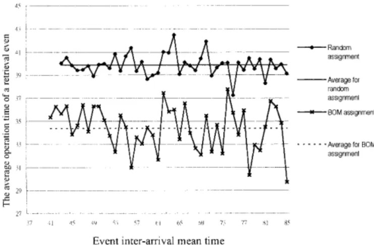
A sufficient time period of 15 000 time units is used for simulating the real operation. The maximum input and output buffer storage is set to 25 lots, respectively. The inter-arrival time of storage or retrieval events is generated by an exponential distribution with a mean in the range of 37–85 time units. The simulation results are shown in Figs 7–12. Figure 7 shows the number of events processed in a time unit by two different storage assignment methods. Figures 8 and 9 show the average operation time of a single storage event and a single retrieval event required by the S/R machine, respectively. Figures 10 and 11 show the average waiting time required for a single storage and a single retrieval event, respectively. Figure 12 shows the average number of waiting events in a time unit by two different storage assignment methods.
From the results of the simulation, several conclusions can be reached. The proposed method may able to deal with a system with a higher event-frequency than the random assign-ment method. Simulation results indicate that steady-state oper-ation can be reached only when the inter-arrival time is greater than 43 time units when the random assignment method is applied. On the other hand, steady-state operation is reached in approximately 40 time units when the proposed method is adopted. The S/R machine operation time and the waiting time for each event, and the number of waiting events are effectively reduced. Therefore, the average operation time and the
influ-Fig. 8. The average S/R machine time required for a storage event by two different storage methods.
Fig. 9. The average S/R machine operation time required for a retrieval event by two different storage policies
Fig. 10. The average waiting time required for a single storage event by two different storage policies
Fig. 11. The average waiting time required for a single retrieval event by two different storage policies.
ence of restrictions on the size of the buffer storage are minimised. The simulation results show the proposed method does improve the performance of an AS/RS, although the illustrated example is a simple one.
Fig. 12. The average number of waiting events in a time unit by two different storage policies.
4. Conclusions
A BOM-oriented class-based storage assignment method for use in a CIM-based AS/RS environment is proposed in this paper. The improvement in AS/RS operations was depicted and illustrated by a simulation example. However, the improve-ment in CIM operations was not discussed. Since the storage attributes of materials and bays are constructed by a BOM structure, all information is digitised and stored in a com-puterised database that can be used to operate an AS/RS in respond to fast environmental variations. Therefore, the pro-posed method can increase the sensitivity of an AS/RS to a production system. It can, of course, improve the performance of the CIM system.
The proposed approach will be compared with other storage methods, such as the dedicated storage assignment method or other class-based storage assignment methods in our future study. Although a single-command S/R machine operation method is used in this paper to provide a quick concept of the proposed method, a dual-command S/R machine operation method will be implemented by the same approach to improve the performance of the proposed method. The use of the proposed BOM-oriented assignment method for implementing a high-efficiency CIM system is a subject deserving further study.
References
1. W. H. Hausman, L. B. Schwarz and S. C. Graves, “Optimal storage assignment in automated warehousing systems”, Manage-ment Science, 22(6), pp. 629–638, 1976.
2. R. Linn and R. A. Wysk, “Expert system based controller for an automated storage/retrieval system”, International Journal of Production Research, 28(4), pp. 735–756, 1990.
3. P. J. Egbelu, “Framework for dynamic positioning of storage/ retrieval machines in an automated storage/retrieval system”, Inter-national Journal of Production Research, 29(1), pp. 17–37, 1991. 4. B. R. Sarker and P. S. Babu, “Travel time modes in automated storage/retrieval systems: a critical review”, International Journal of Production Economics, 40, pp. 173–184, 1995.
5. S. U. Randhawa and R. Shroff, “Simulation-based design evalu-ation of unit load automated storage/retrieval systems”, Computers in Industrial Engineering, 28(1), pp. 71–79, 1995.
6. C. H. Pan and C. H. Wang “A framework for the dual command cycle travel time model in automated warehousing systems”,
Inter-national Journal of Production Research, 34(8), pp. 2099–2117, 1996.
7. T. N. Larson, H. March and A. Kusiak, “A heuristic approach to warehouse layout with class-based storage”, IIE Transactions, 29(4), pp. 337–348, 1997.
8. J. L. Heskett, “Cube-per-order index: a key to warehouse stock location”, Transportation and Distribution Management, 3, pp. 27– 31, 1963.
9. S. C. Graves, W. H. Hausman and L. B. Schwarz, “Storage-retrieval interleaving in automatic warehousing systems”, Manage-ment Science, 23(9), pp. 935–945, 1977.
10. M. J. Rosenblatt and A. Eynan, “Deriving the optimal boundaries for class-based automatic storage/retrieval systems”, Management Science, 34(12), pp. 1519–1524, 1989.
11. A. Eynan and M. J. Rosenblatt, “Establishing zones in single-command class-based rectangular AS/RS”, IIE Transactions, 26(1), pp. 38–46, 1994.
12. B. Muralidharan, R. J. Linn and R. Pandit, “Shuffling heuristics for the storage location assignment in an AS/RS”, International Journal of Production Research, 33(6), pp. 1661–1672, 1995. 13. M. Mansuri, “Cycle-time computation, and dedicated storage
assignment, for AS/RS systems”, Computer and Industrial Engin-eering Proceedings of the 1997 1st International Conference on
Computer and Industrial Engineering, 10–12 March 1997, 33(1– 2), pp. 307–310, 1997.
14. U. W. Thonemann and M. L. Brandeau, “Optimal storage assign-ment policies for automated storage and retrieval systems with stochastic demands”, Management Science, 44(1), pp. 142–148, 1998.
15. H. Mather, “Design, bills of materials, and forecasting the insepar-able threesome”, Production and Inventory Management Journal, 27(1), pp. 90–106, 1986.
16. P. S. Rusk, “Role of bill of material in manufacturing systems”, Engineering Costs and Production Economic, 19(13), pp. 205– 211, 1990.
17. C. H. Chu and S. Nilakanta, “On the design of a micro-based MRP system: a relational database approach”, Computers and Industrial Engineering, 15(1–4), pp. 146–152, 1988.
18. C. P. Koulamas, “Total tool requirements in multi-level machining systems”, International Journal of Production Research, 29(2), pp. 417–437, 1991.
19. N. A. J. Hastings and C. H. Yeh, “Bill of manufacture”, Production and Inventory Management Journal, 33(4), pp. 27–31, 1992. 20. A. J. C. Trappey, T. K. Peng and H. D. Lin, “An object-oriented
bill of materials system for dynamic product management”, Journal of Intelligent Manufacturing, 7, pp. 365–371, 1996.