A Predefined Bit-Plane Comparison Coding
for Mobile Video Applications
Chien-Chen Lin, Yao Li, and Chen-Yi Lee, Member, IEEE
Abstract—For mobile video applications, the required storage
and bandwidth of frame memory play crucial roles. Reducing the accesses and the size of frame memory can decrease area and cost, as well as power consumption. Current video-coding standards can reach high compression efficiency but demand large volumes of computations and storage requirements. Hence, it is hard for these coding standards to be embedded into an H.264 decoder. In this brief, a novel embedded lossy compression scheme is proposed. With a compression ratio at 2, it compresses a 4× 2 size block into 32 bit with peak-signal-to-noise-ratio loss of 1.27∼ 3.94 dB compared with H.264. A pipelined architecture is also proposed to realize both the compressor and the decompres-sor in 2 cycles and 1 cycle, respectively. This cost-effective solution requires a gate count of 4.9 k and power consumption of 244 μW in a 90-nm standard complementary metal–oxide–semiconductor process, making it very suitable for mobile video applications.
Index Terms—Embedded compression (EC), H.264, lossy
com-pression, memory reduction, pattern comparison. I. INTRODUCTION
V
IDEO-CODING standards achieve high compression effi-ciency such as H.264 [1] and so forth. For H.264, at least one previous frame is stored in the external memory device to generate a predicted frame. Obviously, motion compensation (MC) demands a huge amount of data accesses between off-chip memory devices and the video decoder off-chip. However, data transfer consumes a lot of power. For mobile video devices, one major issue is the limited power supply from the battery. It is essential to reduce the bandwidth requirement and the size of frame memory while maintaining acceptable visual quality. Therefore, embedded compression (EC) is a suitable technique to achieve the requirement.EC methods can be categorized majorly into two types: lossless and lossy. Lossless compression algorithms [2], [3] have the advantages of no error propagation and quality loss. However, the variable lengths of the compressed data result in irreducible frame-memory size. Hence, existing lossless algorithms are not suitable for frame compression because their primary purpose is to achieve high coding efficiency rather than low latency, computation complexity, and high random accessibility.
Manuscript received October 6, 2010; revised January 9, 2011 and March 8, 2011; accepted April 25, 2011. Date of publication June 27, 2011; date of current version July 20, 2011. This work was recommended by Associate Editor B.-D. Liu.
The authors are with the Department of Electronics Engineering & Institute of Electronics, National Chiao Tung University, Hsinchu, Taiwan (e-mail: [email protected]; [email protected]; [email protected]).
Digital Object Identifier 10.1109/TCSII.2011.2158271
Lossy compression algorithms, compared with lossless com-pression algorithms, accomplish the fixed comcom-pression ratio (CR). Several lossy compression algorithms have been pro-posed, such as the modified Hadamard transform (MHT) with the quantization of Colomb–Rice coding [4], discrete cosine transform with modified bit-plane zonal coding [5], and so on. Yang and Chai [6] exploit 64 patterns to improve block truncation coding, where Amarunnishad et al. [7] try to enlarge acceptable quality loss by reducing the number of compared patterns in [6]. Lossy compression algorithm with the fixed CR can guarantee the reduction of frame-memory size. However, how to maintain an acceptable visual quality remains to be solved. Consequently, it is important to design a lossy algorithm with the following features: 1) low-distortion visual quality; 2) low complexity; 3) low bandwidth requirement; and 4) low power consumption.
In this brief, a novel embedded lossy algorithm based on predefined bit-plane comparison coding (PBCC) is proposed. The CR is fixed at 2. Each 4× 2 block can be compressed into a 32-bit segment. The proposed PBCC encodes a 4× 2 block in 2 cycles and decodes a 4× 2 block in 1 cycle to meet the requirement of embedded frame data processing.
The rest of this brief is organized as follows. In Section II, a novel algorithm is described briefly. The hardware architecture, which is suitable for mobile video applications, is given in Section III. Sections IV and V discuss the integration with an available H.264 decoder [8] and the experimental results, respectively.
II. PROPOSEDEC ALGORITHM
The proposed algorithm compresses a 4× 2 block (64 bit) from the output of deblocking filters. The CR is fixed at 2, implying that a 4 × 2 block will become a 32-bit segment after compression. With fixed CR, the amount of the coded data is constant. Therefore, this compression can guarantee access times. In addition, in the H.264 standard, a 4× 4 block, which is a basic coding unit, can be partitioned into two 4× 2 blocks. Fig. 1 shows the flowchart of the proposed compression algorithm. We divide the algorithm into four parts: 1) pixel truncation; 2) selective bit planes; 3) rounding; and 4) a pattern comparison. These parts will be described in the following. The compressed 32-bit-segment format is shown in Fig. 2. The representation format consists of a 2-bit mode, a 2-bit start plane (SP), a 2-bit pattern L, a 2-bit pattern R, 12-bit coded data L, and 12-bit coded data R. The mode indicates the selected mode out of four modes, and the SP is derived 1549-7747/$26.00 © 2011 IEEE
Fig. 1. Compression flow of the proposed algorithm.
Fig. 2. Compressed 32-bit-segment format. TABLE I
THREEGROUPS OFEIGHTPATTERNS
Fig. 3. Flowchart of the pixel truncation.
from the bit-plane selection of the selected mode, as shown in Fig. 4. Patterns L and R indicate which group is selected to be compared with the left and right 2× 2 blocks, as shown in Fig. 6. In Table I, coded data L and R pack four patterns or three successive bit planes for the left 2× 2 block and the right 2 × 2 block, respectively.
A. Pixel Truncation
Fig. 3 shows the flowchart of the pixel truncation. First, we calculate the average value (Avg.) of the 4× 2 block and the difference value (Diff.) between the maximum pixel and the minimum pixel of the 4× 2 block. Second, according to Avg. and Diff., we classify those 4× 2 subblocks into five types as follows.
1) Avg. is from 0 to 63, and Diff. is smaller than 32; 2) Avg. is from 64 to 127, and Diff. is smaller than 64; 3) Avg. is from 128 to 191, and Diff. is smaller than 64; 4) Avg. is from 192 to 255, and Diff. is smaller than 32; 5) No change.
value remains unchanged.
B. Selective Bit Plane
Fig. 4 shows the flowchart of the selective bit plane. Bit-plane coding is a well-known method. We exploit the bit plane as a basic unit to a group of numbers, instead of a pixel-wised basic unit. First, we consider a 4× 2 block in which each pixel value is represented by 8 bit. A bit plane can be formed by selecting a single bit from the same position in the binary representation of each pixel. We define that B7 represents the most significant bit (MSB) plane, whereas B0 represents the least significant bit (LSB) plane. Second, the SP is searched for four successive bit planes from the MSB plane with four modes as follows: 1) B7, B6, and B5 are 0× 00; 2) B6 is 0 × FF, and B7 and B5 are 0 × 00; 3) B7 is 0× FF, and B6 and B5 are 0 × 00; and 4) B7 and B6 are 0× FF, and B5 is 0 × 00.
In mode 1, if both B7 and B6 are larger than 0× 00 and B5 is equal to 0× 00, the SP is equal to 2. Similarly, the other modes act like mode 1. Finally, the maximum SP is selected from four modes.
C. Rounding
Since lower bit planes are truncated due to the limited budget, a simple rounding is applied here. When the significant bit of the truncated bits is nonzero and the coded bits are not all in the value of 1, the rounding is applied to each pixel. In Fig. 5(a), this rounding technique can be considered as adding a median number of a lost bit plane. This idea leads to a satisfied quality improvement. Two rounding modes are proposed because the pattern comparison has two data compressed formats. As shown in Fig. 5(b), the first rounding is the comparison code rounding, and the second rounding is the no comparison rounding. For the pattern comparison, the first rounding method is applied to the first three cases, and the second rounding method is only for the last case.
D. Pattern Comparison
The last step encodes the preserving bit planes. First, the truncated 4 × 2 block is partitioned into two 2 × 2 blocks, which are called the left 2× 2 block and the right 2 × 2 block, as shown in Fig. 6(a). In Fig. 6(b), both the left 2× 2 block and the right 2× 2 block exploit the same SP for compression. Sec-ond, four cases for a 2× 2 block are classified as: 1) group A; 2) group B; 3) group C; and 4) no comparison. Through simulation and statistics analysis, the 2 × 2 patterns with a higher hit rate are collected to form one group. The first three cases exploit a group of eight patterns to compare with four successive bit planes from the SP and select one case that can hit three successive bit planes. The three groups of the eight patterns are shown in Table I. If the first three cases are not
Fig. 4. Flowchart of the selective bit plane.
Fig. 5. Flowchart of the rounding.
Fig. 6. Example of partitioning the 4× 2 block.
Fig. 7. Compressor architecture.
matched with these three bit planes, case 4, i.e., no comparison, is chosen, and three successive bit planes from the SP are then stored.
III. PROPOSEDARCHITECTURE
A. Compressor Design
Fig. 7 shows the pipeline architecture of this compressor design. We use two pipeline stages, and each of which requires one cycle. The first stage is the pixel truncation. The second stage is composed of selective bit planes, rounding, a pattern comparison, and a packer. This compressor encodes a 4 × 2 block in 2 cycles.
Fig. 8. Decompressor architecture.
Fig. 9. H.264 decoder with the proposed EC.
B. Decompressor Design
Fig. 8 shows the pipeline architecture of the decompressor. The decompressor only needs one stage with one cycle for parsing, bit-plane decoding, and pattern decoding. This decom-pressor can achieve high throughput, leading to better random accessibility compared with other designs.
IV. SYSTEMINTEGRATION
The overall H.264 decoder with the EC codec is shown in Fig. 9. The data path of the embedded compressor and the decompressor is from the deblocking filter to the external memory device and from the external memory device to MC, respectively. The address controller of EC is simple since the CR is fixed at 2. Our system bus is 32 bit, and the external memory device is 32 bit per entry.
TABLE III PSNR COMPARISON
The specifications of our H.264 decoder platform are HD1080+HD720 at 30 fps with a working frequency at 150 MHz. The compressor converts a 4× 2 block from the deblocking filter into a 32-bit segment, which is stored into the external memory device. Compared with the data access times of the external memory device for the system without EC, the data access times of our system are reduced by half. The decompressor converts a 32-bit segment into a 4× 2 block, which is sent to MC. Since our system bus is 32-bit wide and the external memory device is 32 bit per entry, the system accesses one data as four pixels.
In MC, accessing pixel data is based on the motion vector (MV). Moreover, the x and y values of an MV (x, y) can be classified as follows: 1) Align if the value is quadruple and the required 4 pixels fit into the block grid; 2) Not Align if the value is not quadruple but is an integer and the required 4 pixels traverse two block grids; and 3) Sub if the value accuracy is either 1/2 or 1/4 precision. The required 9 pixels can be obtained by interpolating 4 neighboring pixels.
In Table II, we analyze the read access times of MC with/without EC. The worst case is the (Sub, Sub) case. To finish MC, a 4× 4 block needs a 9 × 9 block. Therefore, the system with/without the proposed embedded compressor takes 15/27 cycles. The best case is the (Align, Align) case. The original system with/without the embedded compressor needs 2/4 cycles to finish the best case. For the other cases, when the required pixels of MC are not fit into 4× 2 block grids, the access times become increased.
V. EXPERIMENTALRESULTS
Table III shows the software simulation results of the pro-posed algorithm, which is integrated with JM16.2. Each test sequence executes 100 frames, such as Akiyo, Foreman, Mo-bile, Stefan, and Station, at ten frames for the I frame interval;
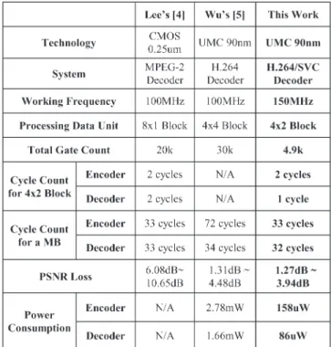
Fig. 10. Simulation result of the station sequence (in HDTV format). quantization parameter is equal to 28; and the bit rate is set as 128 kb/s. The result shows that the peak-signal-to-noise-ratio (PSNR) loss is 1.27 to 3.94 dB, compared with that from H.264. The proposed architecture is synthesized with 90-nm comple-mentary metal–oxide–semiconductor standard-cell library, and the gate counts for the compressor and the decompressor are 4 k and 0.9 k, respectively. The working frequency is up to 150 MHz at HD1080/720. For power consumption, the com-pressor is 158 μW, and the decomcom-pressor is 86 μW.
Table IV shows the comparison with those from previous work. It can be found that our proposed hardware provides less hardware complexity and acceptable visual quality. In partic-ular, the proposed decoder just requires one cycle with better random accessibility for EC without degrading the overall system performance. The power consumption of the proposed hardware is better than those in [4] and [5]. Fig. 10 shows the Station sequence result of the original system with EC in high definition television (HDTV) format. The propagation of
visual quality loss is unavoidable, but the overall video quality remains acceptable.
VI. CONCLUSION
In this brief, we have proposed a new EC algorithm for mo-bile video applications. With these advantages of the proposed EC algorithm, we can reduce the size of external memory and bandwidth utilization to achieve power saving. The pipelined architecture of the proposed decompressor requires 1 cycle; thus, the random accessibility becomes better. Due to the fixed CR, the proposed EC algorithm is easier to be integrated with available video decoders such as the H.264 decoder.
ACKNOWLEDGMENT
The authors would like to thank the National Science Council of Taiwan for sponsoring this research and the members of the SI2 laboratory for their fruitful advice and assistance.
REFERENCES
[1] JVT G050, Draft ITU-T recommendation and final draft international standard of Joint Video Specification (ITU-T Rec. H264-ISO/IEC 14496-10:2005 AVC), 2005.
[2] J. Kim and C. M. Kyung, “A lossless embedded compression using signifi-cant bit truncation for HD video coding,” IEEE Trans. Circuits Syst. Video Technol., vol. 20, no. 6, pp. 848–860, Jun. 2010.
[3] X. Bao, D. Zhou, and S. Goto, “A lossless frame recompression scheme for reducing DRAM power in video encoding,” in Proc. IEEE ISCAS, Jun. 2010, pp. 677–680.
[4] T. Y. Lee, “A new frame-recompression algorithm and its hardware design for MPEG-2 video decoders,” IEEE Trans. Circuits Syst. Video Technol., vol. 13, no. 6, pp. 529–534, Jun. 2003.
[5] Y. D. Wu, Y. Li, and C. Y. Lee, “A novel embedded bandwidth-aware frame compressor for mobile video applications,” in Proc. IEEE ISPACS, Feb. 2009, pp. 1–4.
[6] C. K. Yang and W. H. Tsai, “Improving block truncation coding by line and edge information and adaptive bit plane selection for gray-scale image compression,” Pattern Recognit. Lett., vol. 16, no. 1, pp. 67–75, Jan. 1995. [7] T. M. Amarunnishad, V. K. Govindan, and T. M. Abraham, “Block trunca-tion coding using a set of predefined bit planes,” in Proc. IEEE ICCIMA, Dec. 2007, vol. 3, pp. 73–78.
[8] T. M. Liu, C. C. Chung, C. Y. Lee, T. A. Lin, and S. Z. Wang, “A 125/spl mu/w, fully scalable MPEG-2 and H.264/AVC video decoder for mobile applications,” in Proc. IEEE ISSCC, 2006, pp. 1576–1585.