the channel estimation accuracy in each set of four MIMO-OFDM symbols. Performance evaluation shows that the proposed method achieved a 10% packet error rate of 64 quadrature amplitude modulation (QAM) at 29.5 dB SNR under 120 km/h (Doppler shift is 266 Hz) in 4 4 MIMO-OFDM systems. To decrease complexity, the rich feature of Alamouti-like matrix is exploited to derive an efficient very large-scale integration (VLSI) solu-tion. Finally, this adaptive FD-CE using an in-house 0.13- m CMOS library occupies an area of 3 3.1 mm2, and the 4 4 MIMO-OFDM modem consumes about 62.8 mW at 1.2 V supply voltage.
Index Terms—Adaptive equalizers, input multiple-output (MIMO) systems, orthogonal frequency-division multi-plexing (OFDM), VLSI.
I. INTRODUCTION
M
ULTIPLE-INPUT multiple-output (MIMO) orthogonal frequency-division multiplexing (OFDM) systems offer reliable communications with bandwidth efficiency and high throughput rate. Space–time block code (STBC) has recently been integrated into MIMO-OFDM systems. The combination of MIMO transmission, OFDM technology, and the STBC scheme comprises a promising solution for next-generation wireless communications [1], [2]. The MIMO-OFDM sys-tems, however, require additional complex considerations in signal processing, as compared with single-input single-output (SISO) systems. Recently, the request for wireless communi-cation under mobile conditions has increased. For instance, the very high throughput (VHT) study group wants to go beyond the IEEE 802.11n standard. This study group thinks that MIMO-OFDM technology will be a potential solution to increase the data rate. In addition, the VHT group also con-siders supporting moderate mobility, or equivalently, improving outdoor operations. The VHT study group hopes not only to supply data rate above 1 Gb/s but also to cooperate with the metropolitan area network (MAN). The ability of fast channel tracking is therefore needed to achieve high performanceManuscript received February 08, 2008; revised April 28, 2008. First pub-lished April 07, 2009; current version pubpub-lished October 21, 2009. This work was supported by the National Science Council of Taiwan under Grant NSC95-2221-E-009-093-MY2 and Grant NSC96-2220-E-009-029.
The authors are with the Department of Computer Science, National Chiao Tung University, Hsinchu 300, Taiwan (e-mail: [email protected]; [email protected]; [email protected]; [email protected]).
Digital Object Identifier 10.1109/TVLSI.2008.2005672
performance in mobile applications. For successful transmis-sions, obtaining accurate CSI as soon as possible is extremely important. Advanced military wireless communications and vehicular ad hoc network (VANET) technology (IEEE 802.11p) are other practical applications that will adopt MIMO transmis-sion and STBC. For example, remote-controlled vehicles can access the street and battlefield information from the control center or communicate with other moving vehicles. Robust communication in such environments is very important.
Many studies have investigated MIMO detection, and de-veloped and implemented equalization algorithms [3]–[8]. A scalable STBC decoder [3], supporting 2 2, 8 3, and 8 4 STBCs, was implemented using a low-computational symmetric approach. A 2 2 MIMO-OFDM detector [4] was developed to offer two modes of space–frequency block code and space-division multiplexed OFDM. A vertical-bell laboratory-layered space–time (V-BLAST) detector [5] was based on the square-root algorithm for 4 4 MIMO-OFDM systems. These systems are developed for low mobility. For time-varying environments, Akhtman and Hanzo [6] proposed a decision-directed channel estimation scheme utilizing pilot tones. Song and Lim [7] presented a channel estimation based on particular pilot formats. The channel correlation function [8] was also proposed to exploit the time-varying effects. However, most methods require high complexity and specific pilot formats.
To increase throughput, the number of pilots in MIMO-OFDM systems must be significantly smaller than that of data carriers. The objective of this study is to derive an adaptive frequency-domain channel estimator (FD-CE) for frequency-domain equalization without scattered pilots and specific pilot formats in MIMO-OFDM wireless local area network (WLAN) applications over time-varying fading. Con-versely, a nonpilot-based channel estimator is built to provide acceptable performance. In the proposed FD-CE, all data carriers are applied to measure channel variations, namely, virtual pilots. Consequently, the system with 64 quadrature amplitude modulation (QAM) can achieve a 10% packet error rate at 29.5 dB SNR at 120 km/h (Doppler shift is 266 Hz). Furthermore, the adaptive FD-CE utilizes the rich property of an Alamouti-like matrix to derive an efficient architecture for VLSI implementation. By using an in-house 0.13 m CMOS library, the chip area of the 4 4 MIMO-OFDM modem is 4.6 4.6 mm and power consumption is 62.8 mW at 1.2 V supply voltage.
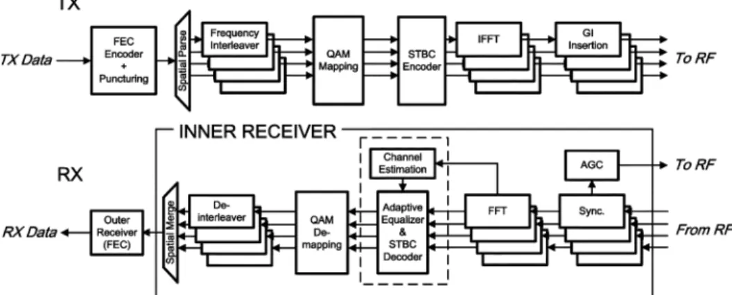
Fig. 1. Block diagram of the 42 4 STBC MIMO-OFDM modem.
The remainder of this paper is organized as follows. Section II introduces the MIMO-OFDM modem specifications and presents the problem statement. Section III describes the mathematical derivations for the proposed adaptive FD-CE. Next, Section IV summarizes the simulation results. Section V then presents the proposed architecture and implementation results. Conclusions are finally drawn in Section VI.
II. SYSTEMDESCRIPTION ANDPROBLEMSTATEMENT
A. Modem Specification
Fig. 1 presents a block diagram of the 4 4 MIMO-OFDM modem. First, source data is scrambled and then encoded by the convolutional encoder. The encoded bit stream is punctured to the required data rate. According to the number of transmit an-tennas, the punctured bit stream is parsed into spatial streams. To prevent a burst error, the interleaver changes the bit order for each spatial stream. The interleaved sequence is modulated by the binary phase-shift keying (BPSK), quadrature phase-shift keying (QPSK), 16-QAM, or 64-QAM scheme. The STBC en-coder is then applied to encode the modulated OFDM (with 64-point IFFT) symbols. Each OFDM symbol has 64 subriers, 52 of which are data carriers and 12 are pilots and null car-riers. The time-domain signal is preceded by the guard interval containing the last 16 samples of the OFDM symbol. After all this, the signal is then transmitted by the RF modules.
The receiver synchronizes the received signals to recognize the OFDM symbols. After fast Fourier transform (FFT), the OFDM symbols are decoded by the STBC decoder with the proposed method. Spatial streams are demodulated to bit-level streams, which are then de-interleaved and merged into a single data stream. Finally, the data stream is decoded by the forward error correction (FEC) block, which has a depuncturer, Viterbi decoder, and descrambler.
B. Problem Statement
In time-varying fading, the system must measure channel variations to prevent equalized degradation. It is known that pilot tones can be applied to extract the channel variations. Getting accurate CSI, the system must increase the number of pilot tones, but it also reduces the data rate. The possible solution is to use the scattered pilots to balance the accurate CSI and data rate. The 2-D methods [9], [10] have been developed
for SISO-OFDM applications. However, most WLANs do not include any scattered pilot, and the number of pilots is also much smaller than that of data carriers (e.g., IEEE 802.11 a/g/n and HiperLAN). Due to the aforesaid limitations, all data carriers should be adopted to ensure accurate estimation of channel variations, namely, virtual pilots.
For VLSI implementation, the hardware complexity of MIMO designs increases greatly; thus, low-complexity ar-chitectures are preferred for MIMO-OFDM modems. For example, the coordinate rotation digital computer (CORDIC) algorithm, which is widely used in vector rotation, can be applied for MIMO detection (e.g., QR decomposition [11], [12]). Although the CORDIC algorithm is advantageous during implementation, the computing latency caused by CORDIC iterations is too long to be suitable for MIMO-OFDM WLAN applications over time-varying fading. To acquire a win–win scenario for latency and throughput, the proposed FD-CE capitalizes on the rich property of an Alamouti-like matrix for an efficient solution.
III. STBC DECODER ANDEQUALIZATION
A. STBC Decoder
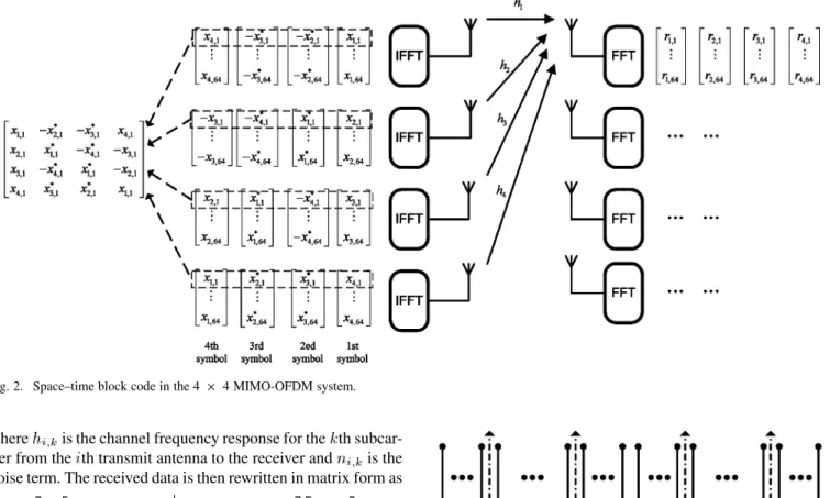
Fig. 2 shows the STBC scheme applied to a MIMO-OFDM system. In MIMO-OFDM systems, STBC is used independently for each subcarrier [13]. For the convenience of explanation, four transmit antennas and one receive antenna are considered. To provide the full rate of 1 (4 symbol periods transmit 4 sym-bols), the following code matrix is chosen
(1)
where , terms represent the transmitted complex data on the subcarrier. Let denote the th received subcarrier at the th symbol duration. The received data over four consec-utive symbol periods at receiver one is expressed as
Fig. 2. Space–time block code in the 4 2 4 MIMO-OFDM system.
where is the channel frequency response for the th subcar-rier from the th transmit antenna to the receiver and is the noise term. The received data is then rewritten in matrix form as
(3) where , , and are 4 1 vectors and is a 4 4 ma-trix. Clearly, all submatrices in are Alamouti-like matrices. The basic 2 2 Alamouti matrix is defined as [14]
(4) where , terms represent the transmitted complex data on the subcarrier. The received symbols can be decoded by the STBC decoder with the estimated CSI. The data is equalized by the following equation
(5) where can be inverted blockwise using the following in-version formula [15]. See (6) at the bottom of the page, where
.
Fig. 3. Subcarrier frequency allocation.
B. Adaptive Frequency-Domain Channel Estimator
Fig. 3 shows the subcarrier frequency allocation. Each OFDM symbol employs 64 subcarriers, 52 are data carriers while the rest are used for pilots and null carries. Four pilots are put in subcarriers 21, 7, and . In general, pilot tones are em-ployed to estimate channel variations in flat-fading channels. In fast-fading channels, it is not suitable to track channel variations of each subcarrier using only four pilots. By injecting additional pilots, accuracy channel variations between consecutive OFDM symbols can be estimated; however, this approach can reduce the data rate. Therefore, the proposed method uses four OFDM symbols (total data carriers 16 pilots) every time to calculate channel variations without injecting additional pilots. In addition, the proposed method is compatible with the current standard because it does not require special pilot patterns.
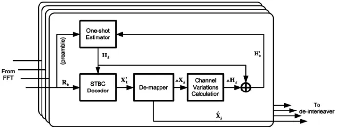
Fig. 4 shows a block diagram of the adaptive FD-CE-based frequency-domain equalizer. First, training symbols are em-ployed to estimate channel frequency response (CFR). The decoded symbols are adopted to extract channel variations. Due to time-varying effects, CSI is not consistent within the
Fig. 4. Block diagram of the adaptive FD-CE-based frequency-domain equalizer.
entire packet. In an adaptive procedure, the estimated CFR is assumed to be , which is defined as
(7) where
(8)
Therefore, the received data are written as
(9) By multiplying both sides of (8) by , the data symbols are estimated by
(10)
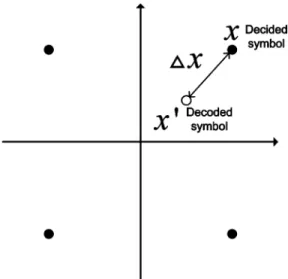
where , , and are 4 1 vectors. Due to time-varying fading, the decoded symbol contains a residual term that causes a decision error, as shown in (10). The relationship between and can be interpreted geometrically in the complex plane (see Fig. 5). The difference between ideal code sets and received symbols is used to extract channel variations. The residual term is expressed as
(11) By defining , (11) can be rewritten as
(12) From (12), the channel variations can be calculated by (13) shown at the bottom of the page. Table I summarizes the oper-ations of the adaptive FD-CE. The adaptive FD-CE is applied
Fig. 5. Relationship between decided symbol and decoded symbol.
TABLE I
OPERATION OF THEADAPTIVEFD-CE
to every four OFDM symbols for 208 tones. Notably, is multiplied by the received OFDM symbols. The decoded sym-bols are employed to calculate the residual term . To acquire , the channel matrix is multiplied by the stored distance vector . After calculating channel variations, is updated by (7).
The 4 4 code matrix, as defined in (1), can be applied to four transmit antennas and any number of receive antennas. In the aforesaid derivation, the receiver takes advantage of the or-thogonality of the code matrix to find a decision statistic. If the receive antenna number is greater than one, we can add all the statistics from all receive antennas. In multiple receive antennas, the additional computational cost includes STBC decoding and scale operations. For instance, the statistics from four receive
antennas are given by , where
the subscript represents the th receive antenna. It is clear that the estimated symbols will be a scale version. To estimate the symbols that were sent, we can scale the decision statistics. This result presented earlier can be directly extended to other STBC codes.
C. Discussion
We provide the discussion with regard to the MIMO system for and . First, we describe the encoding and decoding operations of the Alamouti scheme. The Alam-outi code is an STBC using transmit antennas and any number of receive antennas . The Alamouti code ma-trix is defined in (4). Assuming that the channel coefficients are
(15) There may be applications where multiple receive antennas are feasible. The Alamouti scheme can be applied for the system with multiple receive antennas. Adding all the decision statistics from all receive antennas, the estimated symbols will be a scale version. To estimate the symbols, we can scale the decision statistics. This result presented earlier can be directly extended to other STBC codes.
We discuss the case with transmit antennas subse-quently. In general, the STBC code can be defined by an matrix . The elements of the matrix are combinations of the symbols , . The columns of the matrix represent time slots and the rows denote transmit antennas. Hence, time slots are required to transmit symbols (code rate , where [16]). For transmit antennas, we are more interested in the minimum time slots needed to transmit a block. In summary, STBC systems transmit the same informa-tion stream via different transmit antennas to obtain transmit di-versity. Despite the reduction in the data rate, the STBC system takes the advantage of transmit diversity to obtain robust com-munications. For instance, is the STBC matrix with three transmit antennas. The matrix (code rate ) is given next [13]
(16)
To decode the , the receiver one constructs the decision statistics as follows:
(17) where these parameters are defined in (2). Adding all the de-cision statistics from all receive antennas, the estimated sym-bols will be a scale version. We can scale the decision statistics
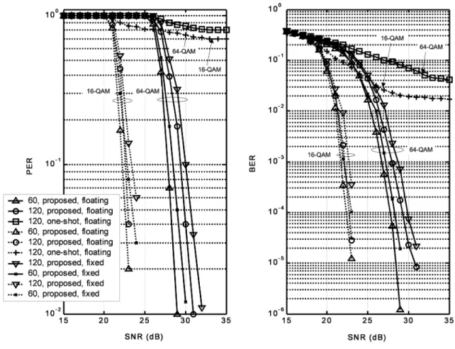
Fig. 6. BER and PER performance.
to estimate the symbols. After the STBC decoding, the differ-ence between ideal constellation points and the received sym-bols can be calculated directly, and then channel variations can be extracted. From (17), it is clear that the computational com-plexity is higher than Alamouti-like case adopted in this study. In system designs, we prefer to choose a feasible STBC matrix that can be decoded by simple liner processing. Alamouti-like matrix is one potential candidate for simple processing among various STBC codewords.
In addition, the complexity of channel estimation scheme also depends on the MIMO detection method. To achieve higher throughput, the spatial-division multiplexing (SDM) technique can be used. With SDM, multiple transmit antennas transmit independent data streams that can be individually recovered at the receiver. An applicable method is required to separate each transmitted stream form other transmitted streams (interference cancellation). Many approaches are known for the detection of SDM signals. For instance, zero-forcing (ZF), minimum mean square error (MMSE), and maximum likelihood (ML) detec-tors estimate the transmitted signals with the estimated channel state information. In general, ML detector provides improved performance over ZF, MMSE detectors. However, the compu-tation complexity of performing a full search for ML detection is too high to be suitable for practical applications. To reduce the complexity, sphere decoding technique or K-best algorithm can be applied to the ML detector. In ZF detector, the detector finds the inversion of the channel matrix to eliminate interfer-ence (i.e., ). If the number of transmit antennas is the same as the number of receive antennas, channel matrix
is a square matrix and the ZF detector has a unique solution . If the channel matrix is not invertible, the ZF detector has a pseudoinverse solution (i.e., , where denotes the Hermitian conjugate). For MMSE detector, the de-tector finds a matrix to minimize the mean square error (MSE)
(i.e., , where is the received data
vector and is the transmitted data vector). From the aforesaid discussion, it is clear that matrix inversion and matrix multiply are required to complete the MIMO detection. Different data de-tection methods have different criteria, and therefore, it is pre-ferred to adopt a reduced-complexity data detection scheme in MIMO systems.
IV. PERFORMANCEEVOLUTION
Similar to IEEE 802.11n [17], the parameters of the 4 4 MIMO-OFDM system employed are as follows: FFT size is 64, the cyclic prefix (CP) is 16 long, system bandwidth is 20 MHz, and, carrier frequency is 2.4 GHz. To ensure the effectiveness of the proposed method, each packet length is set to 1024 bytes. The Jakes method is used to generate time-varying effects during simulations. The Doppler shifts are set to 133 Hz (speed, 60 km/h) and 266 Hz (speed, 120 km/h).1Frequency synchronization is performed to compensate for the frequency shift. The amplitude and phase of channel change signifi-cantly at high Doppler shift. Fig. 6 displays the bit-error rate (BER) and packet-error rate (PER) of the 4 4 MIMO-OFDM 1The Doppler shift can be expressed asf = vf =c, where f is the carrier frequency,c is the velocity of light, and v is the receiver speed.
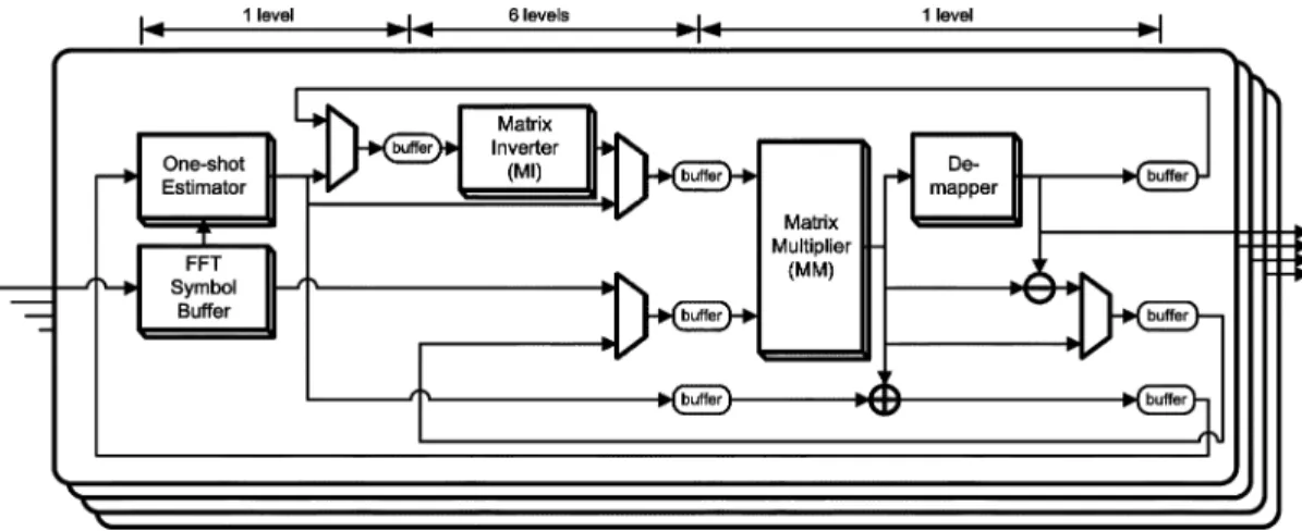
Fig. 7. Architecture of the adaptive FD-CE.
system with and without the proposed adaptive FD-CE. In Fig. 6, “one-shot” legend refers to the case when the proposed adaptive channel estimator is not applied. Obviously, the degra-dation in BER and PER is significant without proper channel tracking in time-varying fading. Simulations also indicate the effectiveness of the proposed adaptive FD-CE that performs well at 28–30 dB SNR for 64-QAM modulation without any irreducible error floor. Thus, this study can be widely applied to time-varying fading.
V. ARCHITECTURE ANDIMPLEMENTATIONS
A. Proposed Architecture
Fig. 7 shows the architecture of the proposed adaptive FD-CE that has four major modules: 1) a one-shot estimator; 2) matrix multiplier (MM); 3) matrix inverter (MI); and 4) demapper. The adaptive FD-CE is pipelined to eight levels since the latency of the MI is long. The one-shot estimator is adopted to measure an initial CSI obtained from training symbols (long preambles) [18], and then updated by means of a feedback mechanism. The de-mapper outputs the point of QAM constellation that has the minimum distance to its input. The key issue of implementations is to build efficient architectures for matrix operations, where the functions of MM and MI are discussed as follows.
From (6), is a square matrix with 2 2 Alamouti sub-blocks. Three 2 2 matrix multipliers and two 2 2 matrix in-verters are needed by the MI. Fig. 8 illustrates the flowchart of matrix inverse computation. For convenience, four letters, , , , and , are used to denote the elements in the matrices. In Fig. 8, the outputs of these three 2 2 matrix multipliers are simply expressed as
(18)
(19)
Fig. 8. Flowchart of matrix inverse computation.
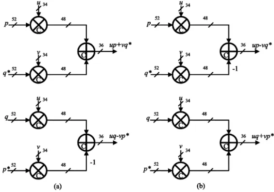
(20) They are all Alamouti-like matrices. Fig. 9 shows the ar-chitectures, where four complex multipliers and two complex adders are needed in a 2 2 matrix multiplier. Fig. 10 shows the architecture of the 2 2 matrix inverter consisting of four square units, three adders, and four dividers. The inverse of a 2 2 Alamouti matrix is still an Alamouti matrix [14]. Notably, only half of the Alamouti-like matrix must be computed—the other half can be derived from the first half via simple sign-flip-ping operations. This characteristic is extremely useful as it can be exploited to derive an efficient architecture for implementa-tion. The MM is utilized for symbol detection, as shown in (10).
Fig. 9. Architecture of MI. The bit width includes real and image parts. (a) Matrix multiplier forH H andH H H . (b) Matrix multiplier for
D H H .
Fig. 10. Architecture of matrix inverter (Alamouti matrix).
For convenience, four letters, , , , and , are used to denote the elements in the matrices. Then, (10) can be rewritten as
(21)
Fig. 11. Architecture of MM. The bit width includes real and image parts.
Fig. 11 shows the architecture of MM. To obtain outputs simul-taneously, 16 complex multipliers and 12 complex adders are
Fig. 13. Chip microphotograph of the 42 4 MIMO-OFDM modem. TABLE II
EXPERIMENTALPARAMETERS
required. Through share and reuse, the implemented cost can be saved.
B. Implementation Results
In the MATLABplatform, an overall system (transmitter, and inner and outer receivers) is constructed to evaluate the perfor-mance. In this chip, the Viterbi decoder is not implemented (lim-ited by chip area). For rapid verification, a 2 2 software-de-fined radio, as displayed in Fig. 12, is constructed. Table II lists the experimental parameters in the software-defined radio. The carrier frequency of each transmit antenna is 2.4 GHz. At the transmitter part, the transmitted data is produced by the MATLABmodule and then these data are stored in memory. The proposed method is mapped onto the field-programmable gate array (FPGA) chips (Xilinx Virtex-II) with on-board 14-bit dig-ital-to-analog converters (D/A). The signals are then transmitted using an in-house RF front-end. Because it is essential to make MIMO transmissions coherent at all D/As and antennas, there is an additional D/A module as a hardware trigger of TX, namely “Sync” in Fig. 12, to control four D/As coherently. After down-converting the RF signals to baseband at the receiver, analog
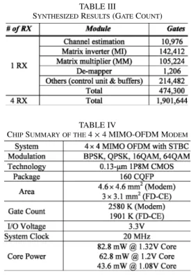
signals are fed into 14-bit A/D converters. The proposed algo-rithm then processes the downconverted signals. The hardware description language (HDL) can be generated as soon as the ar-chitecture with a fixed-point evaluation has been created. After performance assessment and HDL validation, the 4 4 MIMO-OFDM modem (see Fig. 1) is implemented by Taiwan Semi-conductor Manufacturing Company (TSMC) 0.13- m one-poly eight-metal layer (1P8M) CMOS library. Table III presents the synthesized results. Based on synthesis, automatic place and route (APR) can be carried out by SOC encounter (Cadence). Layout versus schematic (LVS) and design rule checking (DRC) must be performed to assess the APR result. Finally, postlayout simulations are performed to verify the clocking, timing, and power of the proposed design. The proposed design passes the SS model (supply voltage: 1.08 V) and temperature 125 C corner simulation. The received data from the SDR platform is applied to chip testing, which is performed to verify the full functionality of the chip using the Agilent 93000 SOC Test System. The modem area is 4.1 4.1 mm , and the area of the proposed FD-CE is 3 3.1 mm (Fig. 13). The memory require-ment for the proposed FD-CE is 50 K bits. Since one adap-tive procedure requires 24.6 to measure four OFDM sym-bols (208 carriers), the efficient throughput is 50 Mb/s with a 64-QAM modulation at 20 MHz. If we use all carriers
of four OFDM symbols to compute the data rate, the data rate is 62.4 Mb/s. The chip area with I/O pads and a power ring is 4.6 4.6 mm . At 1.2 V supply voltage, the power consump-tion is about 62.8 mW. Table IV lists the chip summary of the 4 4 MIMO-OFDM modem.
VI. CONCLUSION
This paper presents an adaptive FD-CE that measures channel variations and prevents performance loss in time-varying fre-quency-selective fading. Without both specific formats and scat-tered pilots, all data carriers can be utilized to ensure accurate
es-timation of channel variations, namely, virtual pilots. Moreover, the proposed FD-CE utilizes the property of the Alamouti-like matrix to decrease the implementation costs of complex opera-tors. Performance evaluations indicate that the proposed FD-CE can be widely applied in time-varying environments. Conse-quently, the 4 4 MIMO-OFDM modem implemented using an in-house 0.13- m 1P8M CMOS library occupies an area of 4.6 4.6 mm and consumes 62.8 mW at 1.2 V supply voltage.
ACKNOWLEDGMENT
The authors gratefully acknowledge the constructive com-ments provided by the anonymous reviewers that have added much to the clarity of this paper. The authors would also like to thank the National Chip Implementation Center (CIC) for pro-viding the service of chip fabrication.
REFERENCES
[1] J. G. Andrews, A. Ghosh, and R. Muhamed, Fundamentals of WiMAX: Understanding Broadband Wireless Networking. Englewood Cliffs, NJ: Prentice-Hall, 2008.
[2] H. H. Chen, Y. C. Yeh, Q. Bi, and A. Jamalipour, “On a MIMO-based open wireless architecture: Space–time complementary coding,” IEEE Commun. Mag., vol. 45, no. 2, pp. 104–112, Feb. 2007.
[3] E. Cavus and B. Daneshrad, “A very low-complexity space-time block decoder (STBD) ASIC for wireless systems,” IEEE Trans. Circuits Syst. I, Reg. Papers, vol. 53, no. 1, pp. 60–69, Jan. 2006.
[4] S. Noh, Y. Jung, S. Lee, and J. Kim, “Low-complexity symbol detector for MIMO-OFDM-based wireless LANs,” IEEE Trans. Circuits Syst. II, Exp. Briefs, vol. 53, no. 12, pp. 1403–1407, Dec. 2006.
[5] Z. Guo and P. Nilsson, “A VLSI implementation of MIMO detection for future wireless communications,” in Proc. IEEE PIMRC, Sep. 2003, pp. 2852–2856.
[6] J. Akhtman and L. Hanzo, “Advanced channel estimation for MIMO-OFDM in realistic channel conditions,” in Proc. IEEE Int. Conf. Commun., Jun. 2007, pp. 2528–2533.
[7] W. G. Song and J. T. Lim, “Channel estimation and signal detection for MIMO-OFDM with time varying channels,” IEEE Commun. Lett., vol. 10, no. 3, pp. 540–542, Jul. 2006.
[8] Y. Li, N. Seshadri, and S. Ariyavisitakul, “Channel estimation for OFDM systems with transmitter diversity in mobile wireless chan-nels,” IEEE J. Select. Areas Commun., vol. 17, no. 3, pp. 461–471, Mar. 1999.
[9] R. Nilsson, O. Edfors, M. Sandell, and P. O. Borjesson, “An analysis of two-dimensional pilot symbol assisted modulation for OFDM,” in Proc. IEEE Int. Conf. Pers. Wireless Commun., Dec. 1997, pp. 71–74. [10] S. Coleri, M. Ergen, A. Puri, and A. Bahai, “Channel estimation tech-niques based on pilot arrangement in OFDM systems,” IEEE Trans. Broadcast., vol. 48, no. 3, pp. 223–229, Sep. 2002.
[11] A. Maltsev, V. Pestretsov, R. Maslennikov, and A. Khoryaev, “Tri-angular systolic array with reduced latency for QR-decomposition of complex matrices,” in Proc. IEEE ISCAS, May 2006, pp. 385–388. [12] L. Boher, R. Rabineau, and M. Helard, “An efficient MMSE equalizer
implementation for 42 4 MIMO-OFDM systems in frequency selec-tive fast varying channels,” in Proc. IEEE PIMRC, Sep. 2007, pp. 1–5. [13] B. Vucetic and J. Yuan, Space-Time Coding. New York: Wiley, 2003. [14] S. M. Alamouti, “A simple transmit diversity technique for wireless communications,” IEEE J. Select. Areas Commun., vol. 16, no. 8, pp. 1451–1458, Oct. 1998.
[15] G. H. Golub and C. F. Van Loan, Matrix Computations. Baltimore, MD: The Johns Hopkins University Press, 1996.
[16] V. Tarkoh, H. Jafarkhani, and A. R. Calderbank, “Space-time block codes from orthogonal designs,” IEEE Trans. Inf. Theory, vol. 45, no. 5, pp. 1456–1467, Jul. 1999.
[17] Wireless LAN Medium Access Control (MAC) and Physical Layer (PHY) Specifications: Amendment 4: Enhancements for Higher Throughput, IEEE P802.11n/D3.00, 2007.
[18] J. Heiskala and J. Terry, OFDM Wireless LANs: A Theoretical and Practical Guide. Indianapolis, IN: Sams, 2001.
Ming-Fu Sun (S’05) received the B.S. and M.S.
degrees in computer science and information en-gineering from National Chiao-Tung University, Hsinchu, Taiwan, in 2003 and 2005, respectively. He is currently pursuing the Ph.D. degree in computer science from the National Chiao-Tung University, Hsinchu, Taiwan.
In 2005, he joined the Institute of Computer Sci-ence, National Chiao-Tung University. During 2006, he was a Lecturer in the Department of Electronics Engineering, Ming Hsin University of Science and Technology. His current research interests include signal processing for wire-less communications, multiple-input multiple-output (MIMO) orthogonal fre-quency-division multiplexing (OFDM) systems, and associated very large-scale integration (VLSI) architectures.
Ta-Yang Juan received the B.S. and M.S. degrees in
computer science and information engineering from National Chiao-Tung University, Hsinchu, Taiwan, in 2004 and 2006, respectively, where he is currently working toward the Ph.D. degree in computer science at the Institute of Computer Science.
His current research interests include signal pro-cessing and channel estimation for MIMO-OFDM communications, and associated very large-scale integration (VLSI) architectures.
Kan-Si Lin received the B.S. degree from the
Depart-ment of Engineering Science, National Cheng-Kung University, Tainan, Taiwan, in 2005, and the M.S. de-gree from the Institute of Computer Science, National Chiao-Tung University, Hsinchu, Taiwan, in 2007.
In 2007, he joined the army for military service as a Platoon Leader. After retirement from the army, he serves in MStar Semiconductor Inc. since 2008. His current research interests include the area of wire-less communications, signal processing, and associ-ated VLSI implementation.
Terng-Yin Hsu (M’07) received the B.S. and M.S.
degrees from Feng Chia University, Taichung, Taiwan, in 1993 and 1995, respectively, and the Ph.D. degree from National Chiao-Tung Univer-sity, Hsinchu, Taiwan, in 1999, all in electronic engineering.
In 2003, he joined the Department of Computer Science, National Chiao-Tung University, where he is currently an Assistant Professor. His cur-rent research interests include VLSI architectures, wireless communications, multispec transmissions, high-speed networking, analog-like digital circuits, system-on-chip (SoC) design technology, and related application-specific ICs (ASIC) designs.