Analytical spatio-temporal design of Kerr lens
mode-locked laser resonators
Kuei-Huei Lin and Wen-Feng Hsieh*
Institute of Electro-Optical Engineering, National Chiao-Tung University, Hsinchu, Taiwan Received April 17, 1995; revised manuscript received January 2, 1996
An analytical method of spatio-temporal design for a Kerr lens mode-locked Ti:sapphire laser is presented. Various spatial and temporal effects are considered to derive simple quadratic equations of the pulse width for both standing- and traveling-wave cavities. By solving the quadratic equation, we obtain the relations be-tween pulse width and other cavity parameters for a given system for optimal design of a Kerr lens mode-locked cavity and to generate the shortest laser pulses. Our theoretical results agree well with the experi-mental results, and the computation time of this analytic approach for cavity parameters is reduced drastically as compared with an iteratively numerical approach. © 1996 Optical Society of America.
1. INTRODUCTION
After the first realization of Kerr lens mode locking in a Ti:sapphire laser by Spence et al.,1 various theoretical studies were dedicated to the Kerr lens mode-locked (KLM) cavity design both numerically2 and analy-tically.3,4 Among these analytical studies, most efforts were concentrated in the spatial domain by assuming a constant beam-spot size in a thin nonlinear crystal to cal-culate the nonlinear round-trip loss for different laser powers and cavity designs. Since an optical pulse will undergo self-phase modulation (SPM) as it propagates through a Kerr medium, temporal-domain analysis of a KLM cavity is also important to optimize output pulse width by compensation of the group-velocity dispersion introduced by a laser crystal and SPM. Using a numeri-cal iterative method, Chilla and Martinez5adopted a tem-poral ABCD matrix method6,7to discuss the KLM proper-ties of a Ti:sapphire laser. Because their method involves iterative manipulation of a seeding pulse to get steady-state output, a lot of computation time is needed. Also, with the assumption of a constant beam radius in the Kerr medium and without astigmatism compensation, their method has to reduce the nonlinearity by a factor of 3 to meet the experimental result.8
In our previous studies,9,10by introducing a renormal-ized q parameter in a Kerr medium,11 we obtained a quartic equation of the beam-spot size at the output cou-pler in a general standing-wave KLM laser cavity and a quadratic equation of that for a ring cavity with astigma-tism compensation. Thus the beam-spot variation throughout the Kerr medium can be calculated by ABCD transformation. Based on these spatial results as well as the concept of temporal ABCD transformation,6,7we es-tablished a general spatio-temporal approach to analyze steady-state KLM cavities. The temporal ABCD matri-ces included in our formulation to describe various linear and nonlinear temporal effects are nonlinear absorption, near-resonance phase shift, group-velocity dispersion, dis-persion compensation, bandwidth limiting, and self-phase modulation. The first two matrices are directly adopted
from Ref. 7, and we derive the other matrices from a co-herent pulse transformation integral. Particularly, the spot-size variation in a Kerr medium obtained from the spatial results9,10were considered in a SPM matrix.
We further assumed that the peak intensities of intra-cavity laser pulses are not so high that the commutation of the characteristic matrices of corresponding nonlinear effects still satisfy the commutation law. This is true for a pulse width of not less than 50 fs under intracavity pulse energy of 200 nJ. Therefore we can combine equivalent complex quadratic phase-modulator matrices and nonlinear absorption matrices. By properly choosing a self-consistent point at the cavities for temporal p pa-rameters, we can derive a simple quadratic equation for pulse width. After solving this quadratic equation, we obtain the relation between pulse width and other cavity parameters. We found that the optimal prism separa-tions are shorter for broader cavity bandwidths, and the pulse width depends more strongly on the prism separa-tion. We also found that the optimal prism separations for high-energy pulses are shorter than for low-energy pulses and that this difference is more distinct in the narrower-bandwidth case. As the intracavity pulse en-ergy increases, the pulse width begins to decrease, which is a result of stronger SPM and generation of more fre-quency components. Using our formulation, we explain why a traveling-wave cavity is capable of generating shorter pulses than a standing-wave cavity. Since our analytical method has taken into account the beam-radius variation inside the Kerr medium, not only good agreement with experimental results is obtained, but also the computation time is reduced drastically as compared with iteratively numerical methods.5
2. SPACE
–
TIME ANALOGY AND
TEMPORAL ABCD MATRICES
There exists an interesting analogy between the spatial problem of Fresnel diffraction and the temporal problem of dispersive pulse propagation.6,7 Under proper change of variables, formulas describing spatial Gaussian beams
can be applied to temporal Gaussian pulses. By this space–time analogy, the exceedingly complicated problem of coherent pulse propagation through a general optical system can be handled in a manner similar to the ray-matrix approach of Gaussian-beam propagation. We may proceed from different starting points to derive the space–time formula analogy. One of the commonly adopted starting points is the analogy between the paraxial wave equation and the dispersive wave equation; another starting point is the analogy between the Fresnel diffraction integral and the coherent pulse transforma-tion integral. These different approaches will lead to dif-ferent sets of variable substitution in a space–time anal-ogy as well as different temporal matrices. In this paper we adopt the approach of the integral analogy.
By this space–time analogy,7 we can write the pulse amplitude A(t) and the complex time parameter p as
A~t! 5 A0 exp
S
ict 2 2pD
exp~ict/h!, (1) 1 p 5 2r c 1 i 2 cs2, (2) wherehis a complex effective refractive index determin-ing the shifts of the central carrier frequency and the po-sition of the pulse maximum and wherer and s are chirp-ing and pulse width of the Gaussian pulse. The temporal ABCD matrix for a dispersive medium of length z (with refractive index n 5 n01 n1v) is MS5F
1 S 0 1G
5F
1 2zn1 0 1G
; (3)where S5 2n1z, and the matrix for phase modulator
[with transmission coefficient T5 T0exp(iat2 1 ibt)] is
Ma5
F
1 0
2a
c 1
G
. (4)
The p parameter is equivalent to the spatial q parameter and satisfies the temporal ABCD law as
pout5
At p1 Bt
Ct p1 Dt
, (5)
where At, Bt, Ct, and Dt are the temporal matrix
ele-ments.
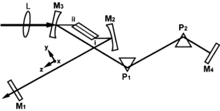
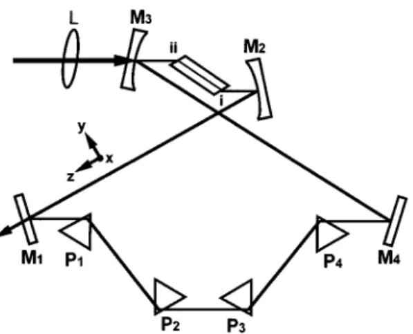
For the four-mirror figure-x standing-wave Ti:sapphire laser with intracavity dispersion-compensation prisms shown in Fig. 1, the equivalent block diagram considering various linear and nonlinear temporal effects are shown in Fig. 2, including material dispersion of the crystal, group-velocity dispersion compensation, bandwidth limit-ing, near-resonance phase shift, nonlinear absorption, and self-phase modulation. The above effects also exist in the four-mirror figure-8 traveling-wave cavity of Fig. 3, and the equivalent block diagram is shown in Fig. 4. In our formulation we do not consider the interplay between SPM and dispersion in the Kerr medium; i.e., we assumed that the peak intensities of intracavity laser pulses are not so high such that the commutation of these character-istic matrices of corresponding nonlinear effects still holds. This approximation can give reasonable agree-ments with experimental results for a pulse duration longer than 50 fs. For KLM cavities capable of generat-ing shorter pulses, numerical methods must be adopted to obtain better predictions.
The near-resonance phase shift and nonlinear absorp-tion matrices can be found in Ref. 7. For a near-resonance phase shift,
MNR5
F
1 2 iNsczT22c
0 1
G
5F
1 2 iGT22c
0 1
G
, (6)where N is the population inversion, sc is the cross
sec-tion, T2 is the transverse relaxation time of the transi-tion, and G is the single-pass power gain. For nonlinear absorption with transmission coefficient T5 T0exp [kuA(t)u2], MNA5
F
1 0 2a c 1G
5F
1 0 i 4kA0 2 cs2 1G
. (7)Now we proceed to derive the other temporal ABCD matrices representing group-velocity dispersion, SPM, bandwidth limiting, and dispersion compensation by a prism pair, respectively.
A. Group-Velocity Dispersion
Consider that the propagation constantb(v) for coherent pulses propagating in the dispersive Ti:sapphire crystal can be approximated by the first three terms of its Taylor series expansion around center frequencyv0as
b~v! 5 vc n~v! 'b01b8~v 2 v0! 1 12 b9~v 2 v0!2. (8) Letv
8
5v 2 v0; thenFig. 1. Four-mirror figure-x standing-wave laser with a Kerr medium of length Lcplaced between two curved mirrors. A pair of Brewster-angle dispersive prisms P1and P2are placed in the
cavity to achieve group-velocity compensation of the laser pulses.
Fig. 2. Block diagram illustrating the six temporal effects in Fig. 1.
v8
c n~v8! 'b01
v8
c ~n01 n1v8!, (9)
where n05b
8
c and n1 5 1/2b9
c. Therefore we know from Eq. (3) that the temporal ABCD isMDTC5
F
1 2zn1 0 1G
5F
1 b9cz 0 1G
. (10) B. Self-Phase ModulationFor optical pulses passing through a thin Kerr medium the transmission coefficient (under parabolic approxima-tion) is T ' T0 exp
S
i4pn2A0 2L c acl t2 s2D
5 exp~iat 2!, (11)where a5 4pn2A02Lc/(acls2); n2, ac, and Lc are the
nonlinear refractive index, the correction factor, and the length of the Ti:sapphire crystal, respectively. The tem-poral ABCD matrix of this phase modulator is
MSPM5
F
1 0 2a c 1G
5F
1 0 8pn2A02Lc acl 1 cs2 1G
. (12)However, for a thick Ti:sapphire rod, since the Gaussian beam is tightly focused in the crystal, spatial variation of
the beam spot must be taken into account. Thus A0 is not constant, and the A02Lc term in the above equation
should be replaced by an integration from 0 to Lc.
Therefore MSPM5
F
1 0 2a c 1G
5F
1 0 8pn2 acl 1 cs2E
0 Lc A02dz 1G
. (13) The integration in the above equation can be related to spatial Gaussian q parameters which can be analytically calculated from Refs. 8 and 9. Let the q parameter on surface I and in the Ti:sapphire crystal be1 q1 5 1 R1 2 i 1 y1 5 1 R1 2 i l npw12 , 1 q2 5 1 R2 2 i 1 y2 5 1 R2 2 i l npw22, respectively. Since A025 2P pw22 5 2nP ly2 5 2nP l 1
S
y1 nR12 1 1 2 K 2y1D
z21 2y1 R1 z 1 ny1 , (14) we haveE
0 Lc A02dz 5 2nP lE
0 Lc 1S
y1 nR12 1 1 2 K 2y1D
z21 2y1 R1 z1 ny1 dz. (15) The integration can be calculated easily by the following formula:E
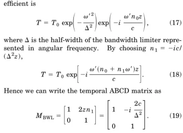
dz az21 bz 1 c 5 2 ~4ac 2 b2!1/2tan 21 2az1 b ~4ac 2 b2!1/2. (16) C. Bandwidth LimitingTo adjust the central wavelength of the pulses, one may insert a birefringent filter in the laser cavity; therefore the oscillation bandwidth will be limited. Even if this real filter may be absent in order to generate the shortest femtosecond pulses, other effects will still limit the pulse-width shortening, such as third- and higher-order disper-sion, birefringent filtering caused by the Brewster-cut Ti:sapphire crystal, and the effect of the dispersion-compensation prism. These effects are equivalent to bandwidth limiters and must be included in our model. We approximate the spectral response of the above mechanisms by Gaussian-shaped functions.
Fig. 3. Four-mirror figure-8 ring cavity laser with a Kerr me-dium of length Lc placed between two curved mirrors. Four Brewster-angle dispersive prisms P1, P2, P3, and P4are placed in the cavity to achieve group-velocity compensation of the laser pulses.
Fig. 4. Block diagram illustrating the six temporal effects in Fig. 3.
For a Gaussian bandwidth limiter the transmission co-efficient is T5 T0 exp
S
2v8 2 D2D
expS
2i v8n0z cD
, (17)whereD is the half-width of the bandwidth limiter repre-sented in angular frequency. By choosing n1 5 2ic/ (D2z),
T 5 T0 exp
F
2iv8~n01 n1v8!zc
G
. (18)Hence we can write the temporal ABCD matrix as
MBWL5
F
1 2zn1 0 1G
5F
1 2i 2c D2 0 1G
. (19)Comparing Eqs. (6) and (19), we found that the effect of a near-resonance phase shift is equivalent to bandwidth limiting.
D. Dispersion Compensation of the Prism Pair
For a single pass through the dispersion-compensation prism pair the effective negative group-velocity dispersion is12 b9z5 2 2l 3 pc2
S
dn dlD
2 Lp1 l3 pc2F
d2n dl2 1S
2n2 1 n3DS
dn dlD
2G
dp, (20) where Lpis the prism separation and dpis the insertion width of the laser beam in the second prism P2. The derivation of Eq. (20) is based on the marginal insertion of prisms; i.e., the cavity beam propagates through the apexes of both prisms. However, in a real system, deeper insertions are needed to reduce intracavity loss, as de-picted in Fig. 5, wheree is the apex angle, dp1and dp2are insertion width for P1and P2, respectively. Under such circumstances, the positive material dispersion for pulses propagating through the prisms cannot be neglected. A positive term of 2bp9
tan(e /2)(dp11 dp2), wherebp9
is thematerial dispersion of prisms, must be included in Eq. (20). In addition, dpcan be approximated by twice the angular dispersion:12,13 dp5 4 sin~e/2! @1 2 n2 sin2~e/2!#1/2 dn dl DlLp, (21) whereDl is the FWHM bandwidth of the intracavity laser spectrum. Therefore the effective negative group-velocity dispersion becomes
b9z 5 2 2l 3 pc2
S
dn dlD
2 Lp1 l3 pc2F
d2n dl2 1S
2n2 1 n3D
3S
dn dlD
2G
4 sin~e/2! @1 2 n2sin2~e/2!#1/2 dn dl DlLp 1 l 3 pc2 d2n dl2 tan~e/2!~dp11 dp2!. (22) The temporal ABCD matrix for the prism pair isMDPP5
F
1 2zn1
0 1
G
5F
1 b9zc
0 1
G
, (23)withb
9
z given in Eq. (22).3. ANALYTICAL SPATIO-TEMPORAL
FORMULATION OF KLM CAVITIES
In a previous paper9 we derived a quartic equation of
y05 hpw02/l at the output coupler for a four-mirror standing-wave cavity of Fig. 1,
a4~y02!41 a3~y02!31 a2~y02!21 a1~y
02! 1 a15 0, (24) where the coefficients a4, a3, a2, a1, and a0are functions of Kerr medium length Lc, intracavity power P, and
ma-trix elements of spatial matices. After Eq. (24) is solved to give the beam radius at the output coupler, the beam radius within the Kerr medium can be calculated by the spatial ABCD law and renormalized q parameter propa-gation, and then the temporal matrix for nonlinear ab-sorption and SPM can be calculated from Eqs. (7) and (13). In another paper10we have also analyzed the spa-tial behavior of the four-mirror figure-8 traveling-wave cavity in Fig. 3. The q parameters throughout the traveling-wave cavity can be calculated by solving an al-gebraically quadratic equation for an arbitrarily thick Kerr medium and an intracavity laser power less than self-trapping power. Again the temporal matrix for non-linear absorption and SPM can be calculated from Eqs. (7) and (13).
Now we can proceed to find characteristic equations that describe the behavior of pulse width and chirping in the KLM cavity. As we can see from Figs. 2 and 4, the temporal effects undergone by pulses in the standing-wave and the traveling-standing-wave cavities during a round trip differ only in their magnitude. For a traveling-wave cav-ity the pulses will undergo those temporal effects (except for prism-pair compensation) only once in a round trip but twice for a standing-wave cavity. Therefore in the fol-lowing formulation we consider the standing-wave cavity only. The obtained results can be applied to the traveling-wave cavity after proper substitutions.
Fig. 5. In a real laser cavity, deeper prism insertions are needed to reduce intracavity loss. Hereeis the apex angle, and dp1and
The six matrices of Fig. 2 can be lumped into two ma-trices:
F
1 a 1 ib 0 1G
, (25)F
1 0 g 1 id 1G
. (26)Let the reference plane be plane I; the round-trip tempo-ral matrix is
F
At Bt Ct DtG
5F
1 1 4~a 1 ib!~g 1 id! cs2 2~a 1 ib! 2~g 1 id! cs2 1G
. (27) The steady-state p parameter can be solved from Eq. (5) by assuming pout5 p owing to self-consistency. After some simple manipulation, we have1 p 5 Dt2 At 2Bt 6 @~Dt1 At!22 4#1/2 2Bt . (28)
Substituting Eqs. (2) and (27) into Eq. (28), we have
Equating the real part with the imaginary part in Eq. (29), we obtain a set of simultaneous equations of vari-ablesr and s : 4r2s41 4grs22 4~d1 1! 5 c~ag 1 bd! a21b2 s 2, (30) 4g 1 4~d1 2!rs25c~ad2 bg! a21b2 s 2. (31)
After some tedious manipulations, a single variable equa-tion of pulse widths is derived:
c2~ad2bg!2s41 4c~a21b2!@gd~ad2bg! 2 ~d1 2!2~ag 1 bd!#s22 16~d1 1!
3 ~a21b2!2@g21 ~d1 2!2# 5 0, (32) and the chirpingr is
r 5 1 4~d1 2!
F
c~ad2bg! a21b2 2 4 g s2G
. (33) Since Eq. (32) is a quadratic equation ofs2, the pulse width at plane I of the Kerr lens mode-locked laser sys-tem can be solved by an analytical approach. Using sys- tem-poral ABCD transformation, we can calculate the pulse widths throughout the laser cavity. For example, the chirpingr1and the pulse widths1at output coupler are related tor and pulse width s at plane I byr15 r 2 2ar 2 c 2 2a cs4
S
12 2ar c 2 2b cs2D
2 1S
2a cs22 2br cD
2, (34) s15S
1 2 2ar c 2 2b cs2D
2 1S
2a cs22 2br cD
2 1 s22 2br2 c 2 2b cs4 . (35)4. KLM Ti:SAPPHIRE LASER SYSTEM
DESIGN
As an example to demonstrate the applicability of the above-mentioned analytical approach, we consider a figure-x standing-wave Ti:sapphire laser, as shown in Fig. 1, with a 20-mm-long Ti:sapphire laser rod as a Kerr me-dium (n0 5 1.76, n25 3 3 10220m2W21, correction fac-tor a ; 5.35, Pcr; 2.6 MW, and single-pass group-velocity dispersion of 1280 fs2, as in Ref. 14). The distance between M1and M2is d15 70 cm, the distance
between M3and M4is d25 100 cm, and the focal length of the curved mirrors is f5 5 cm with a separation of 11.4 cm, which is located near the center of the second stable range. The Brewster-angle dispersive prisms are made of SF10, with apex angle « 5 60.6°, refractive index n5 1.71125, dn/dl 5 20.04958 mm21, and d2n/dl25 0.1755mm22. As reported by several research groups, the mode-locked average power is approximately equal to that of steady-state cw. After pumping and cav-ity parameters (such as cavcav-ity length, mirror curvature, reflection loss of mirrors, and doping concentration of Ti31) are specified, the cw average power can be calculated,15 and the intracavity mode-locked pulse en-ergy can be estimated accordingly. Since the Ti:sapphire laser is usually pumped far above its threshold, the spec-tral gain bandwidth is much larger than any other band-width limiter in the cavity, and thus the effect of a near-resonance phase shift can be neglected. Also, we will not consider the nonlinear gain for already saturated gain in the steady-state condition.
Now we may begin to analyze the spatio-temporal be-havior of the KLM cavity. Substituting these data into the temporal ABCD matrices and using K 5 P/Pcr, Lp, andDl as parameters, we solve for the output pulse width s of the KLM cavity. The obtained relation between s and K can further be transformed to the relation between s and intracavity pulse energy E, since E 5 (p/2)1/2 3 KPcrs. In the results of the following calculations the pulse widths are given by the FWHM value Dt 5 (2 ln 2)1/2s. 2r c 1 i 2 cs2 5 2 ~g 1 id! cs2 6
F
16~a 1 ib!2~g 1 id!2 c2s4 1 16~a 1 ib!~g 1 id! cs2G
1/2 4~a 1 ib! . (29)Figure 6(a) shows the dependence of output pulse widths Dt on the single-pass prism-pair dispersion for Dl 5 10 nm and Dl 5 20 nm, respectively. The intrac-avity pulse energy is 120 nJ, corresponding to 700-mW output power with 7% coupling. We found that the opti-mal prism separations for 10-nm and 20-nm bandwidths are different. For Dl 5 10 nm, the shortest output pulses (147 fs) are obtained with 22780-fs2 prism-pair dispersion, which corresponds to Lp5 59 cm (the prism insertions dp1and dp2were chosen as 5 mm and 6 mm, respectively, for low round-trip loss), while for Dl 5 20 nm the shortest output pulses (67 fs) are obtained with 21772-fs2 prism-pair dispersion, which corresponds to
Lp5 40.5 cm (now dp1and dp2are chosen as 3 mm and 4 mm, because in a real system one has to minimize the
prism insertion to reduce the more severe higher-order dispersion in the sub-50-fs regime). In order to generate the shortest pulses for the KLM laser, we make the total intracavity dispersion negative. The above differences in prism separation and insertions must be taken into ac-count in the practical KLM laser constructions. Further-more, we notice that for broader bandwidth the pulse-width depends more strongly on the prism separation. A decrease of 20-cm separation broadens the pulse to 385 fs (5.7 times) for the 20-nm bandwidth case but only to 170 fs (1.2 times) for the 10-nm case. As a comparison, the dependence of output pulse widths on prism-pair disper-sion for a pulse energy of 180 nJ is shown in Fig. 6(b). We find that the optimal prism-pair dispersion for gener-ating the shortest pulses is reduced, which is 22286 fs2 for Dl 5 10 nm and 21659 fs2 for Dl 5 20 nm. The change of optimal dispersion compensation is more dis-tinct in the narrower bandwidth case. We also notice that the shortest pulse obtainable for a 10-nm bandwidth is reduced to 137 fs, while it is almost unchanged for the 20-nm case.
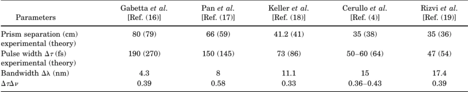
Table 1 lists several published systems of a mode-locked Ti:sapphire laser4,16–19and our theoretical calcula-tions, in which Ti:sapphire crystal lengths are equal (2 cm) and the prism materials are also SF10. Since some of these papers do not give detailed values of cavity length, intracavity power, or prism insertions, we adopt typical values. The calculated optimal prism separation and shortest pulsewidth are very close to the experimen-tal results (within 10% and 30%, respectively), which is apparently better than the iterative numerical approach,5 in which the nonlinearity is overestimated and n2 must be corrected to be 3 times less than the real value. We notice that for systems generating shorter pulses (broader bandwidth), the prism separations are also shorter, which is consistent with our theoretical prediction.
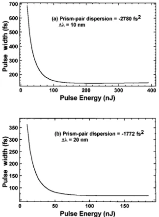
In certain circumstances we may increase the pump power to obtain higher output; then the SPM in the Ti:sapphire crystal changes as a result of increasing intracavity power. In order to realize the effect of SPM on pulse width, the dependence ofDt on pulse energy E is depicted in Figs. 7(a) and 7(b) for Dl 5 10 nm and Dl 5 20 nm, respectively. The pulse widths are calculated at a 22780-fs2 prism-pair dispersion for a 10-nm band-width and a21772-fs2dispersion for a 20-nm bandwidth. We find that as the intracavity pulse energy increases, the pulsewidth begins to decrease, which is a result of in-creasing SPM. However, when the pulse energy is larger than 140 nJ for a 10-nm bandwidth and 70 nJ for a 20-nm bandwidth, the pulse widths are almost unchanged. Fig. 6. Calculated FWHM pulse width at the output coupler of a
standing-wave cavity for 10-nm and 20-nm intracavity band-widths as functions of prism-pair dispersion with (a) intracavity pulse energy of 120 nJ and (b) intracavity pulse energy of 180 nJ. The distance between curved mirrors is 114 mm.
Table 1. Prism Separation and Temporal Characteristics of Published Ti:Sapphire Laser Systems
Parameters Gabetta et al. [Ref. (16)] Pan et al. [Ref. (17)] Keller et al. [Ref. (18)] Cerullo et al. [Ref. (4)] Rizvi et al. [Ref. (19)] Prism separation (cm) experimental (theory) 80 (79) 66 (59) 41.2 (41) 35 (38) 35 (36) Pulse widthDt(fs) experimental (theory) 190 (270) 150 (145) 73 (86) 50–60 (64) 47 (54) BandwidthDl (nm) 4.3 8 11.1 15 17.4 DtDn 0.39 0.58 0.33 0.36–0.43 0.39
Next, we may compare the standing-wave cavity with the traveling-wave cavity of the same cavity length and optical components (except for an addition pair of prisms in the traveling-wave cavity). For the same output power of 700 mW the intracavity pulse energy is 240 nJ because the pulse repetition rate is only half that of the standing-wave cavity. In Fig. 8(a) we plot the output pulse widths as a function of prism separations for Dl 5 10 nm. We find that the shortest pulses (95 fs) are ob-tained with a2926-fs2prism-pair dispersion (correspond-ing to Lp5 27 cm, dp15 3 mm, and dp25 4 mm; round-trip dispersion is21852 fs2), which is quite different from the standing-wave case shown in Fig. 6(a). Since the pulses in a traveling-wave cavity propagate through the bandwidth limiter only once in a round trip, whereas for standing-wave pulses it is twice, the effective bandwidth of the traveling-wave cavity is thus
A
2 times that of the standing-wave cavity, as can be seen from Eq. (19). Therefore a traveling-wave cavity is capable of producing pulses shorter than the standing-wave cavity. The de-pendence of Dt on pulse energy E for a traveling-wave cavity is depicted in Fig. 8(b). Again we find that the pulse width decreases as the intracavity pulse energy in-creases, which is the same as for a standing-wave cavity. Finally, let us compare theoretical predictions of this analytical spatio-temporal approach with the experimen-tal results of our self-starting KLM Ti:sapphire.20 At 5-W pumping, the shortest pulses are obtained with prism separation Lp5 60 cm. The prism insertions aredp15 5 mm and dp25 6 mm. The distance between M1 and M2is 70 cm, and the total length between M3and M4 is 100 cm; the distance between end face I and M2is 49 mm, and the distance between end face II and M3 is 47 mm. The total output power (7% coupling) is 700 mW, corresponding to an intracavity pulse energy of 120 nJ. Assuming a sech2pulse shape, the pulse width is 146 fs. From Fig. 6(a) we can see that the shortest output pulse width is 147 fs, which is obtained with a prism separation of 59 cm. Both the optimal prism separation and the shortest pulse width are very close to the experimental re-sults, which demonstrates the accuracy of our analytical approach.
In practical systems, higher-order dispersive effects will limit the minimum achievable pulse width even though the second-order dispersion in the KLM cavity has been compensated. In fact, it was the reduction of higher-order dispersions that led to the decrease of pulse durations from ;50 fs to the sub-10-fs regime. Since higher-order dispersion does not act as a Gaussian fre-quency filter, precise formulation of the pulse duration, the beam-spot size, and the KLM cavity design are be-yond the scope of our analytical second-order theory. An estimation of the amount of bandwidth limited by higher order dispersions can be found in other papers.21
How-Fig. 7. Calculated pulse width at the output coupler of a standing-wave cavity as a function of intracavity pulse energy: (a) 10-nm bandwidth,22780-fs2prism-pair dispersion; (b) 20-nm
bandwidth,21772-fs2prism-pair dispersion.
Fig. 8. (a) Output pulse width of a traveling wave cavity for a 10-nm intracavity bandwidth as a function of prism separation with intracavity pulse energy 240 nJ. The distance between curved mirrors is 112 mm. (b) Output pulse width of a traveling-wave cavity as a function of intracavity pulse energy. The bandwidth is 10 nm, and the prism-pair dispersion is 2926 fs2.
ever, analytic spatio-temporal higher order theory has, to our knowledge, not been established and is worth study-ing in the future.
5. CONCLUSIONS
In this paper we have established a general but simple spatio-temporal approach to study both the standing- and the traveling-wave Kerr lens mode-locked (KLM) laser resonators. Various spatial and temporal effects are combined to derive simple quadratic equations of pulse width for both standing- and traveling-wave cavities. By solving the quadratic equation, we obtain the relations between pulse width and other cavity parameters. We find that the optimal prism separations are shorter for broader cavity bandwidths, and the pulse width depends more strongly on the prism separation. This fact is con-sistent with published papers. We also find that the op-timal prism separations for high-energy pulses are shorter than for low-energy pulses, which is more distinct in the narrower-bandwidth case. As the intracavity pulse energy increases, the pulse width begins to de-crease, which is a result of stronger SPM and generation of more frequency components. We have explained why a traveling-wave cavity is capable of generating shorter pulses than a standing-wave cavity even if higher-order effects are not introduced. As compared with a numeri-cal approach, the computation time of our analytic ap-proach for cavity parameters has been reduced drasti-cally, yet without loss of accuracy in the prediction of experimental results. Finally, we compare theoretical predictions of this analytical spatio-temporal approach with the experimental results of our self-starting KLM Ti:sapphire. Both the optimal prism separation and the shortest pulse width are very close to the experimental re-sults, which demonstrates the accuracy of our analytical approach.
ACKNOWLEDGMENT
The authors acknowledge partial financial support, and one of the authors, K. H. Lin, thanks the National Science Council, Taiwan, for a Ph.D. scholarship under grant NSC83-0208-M-009-066.
*E-mail address, [email protected].
REFERENCES
1. D. E. Spence, P. N. Kean, and W. Sibbett, ‘‘60-fs pulse gen-eration from a self-mode-locked Ti:sapphire laser,’’ Opt. Lett. 16, 42 (1991).
2. G. W. Pearson, C. Radzewicz, and J. S. Krasinski, ‘‘Analysis of self-focusing mode-locked lasers with additional highly nonlinear self-focusing elements,’’ Opt. Commun. 94, 221 (1992).
3. T. Brabec, Ch. Spielmann, P. E. Curley, and F. Krausz, ‘‘Kerr lens mode locking,’’ Opt. Lett. 17, 1292 (1992). 4. G. Cerullo, S. De Silvestri, V. Magni, and L. Pallaro,
‘‘Reso-nators for Kerr-lens mode-locked femtosecond Ti:sapphire lasers,’’ Opt. Lett. 19, 807 (1994).
5. J. L. A. Chilla and O. E. Martinez, ‘‘Spatial-temporal analy-sis of the self-mode-locked Ti:sapphire laser,’’ J. Opt. Soc. Am. B 10, 638 (1993).
6. S. P. Dijaili, A. Dienes, and J. S. Smith, ‘‘ABCD matrices for dispersive pulse propagation,’’ IEEE J. Quantum Electron. 26, 1158 (1990).
7. O. O. Silichev, ‘‘Matrix method for calculations on the propagation of coherent laser pulses,’’ Quantum Electron. 23, 855 (1993).
8. L. Spinelli, B. Couillaud, N. Goldblat, and D. K. Negus, ‘‘Starting and generation of sub-100-fs pulses in Ti:Al2O3by
self-focusing,’’ in Lasers and Electro-Optics, Vol. 10 of 1991 OSA Technical Digest Series (Optical Society of America, Washington D.C., 1991), paper CPDP7.
9. K.-H. Lin and W.-F. Hsieh, ‘‘An analytical design of sym-metrical Kerr lens mode-locking laser cavities,’’ J. Opt. Soc. Am. B 11, 737 (1994).
10. K.-H. Lin, Y. Lai, and W.-F. Hsieh, ‘‘A simple analytical method of cavity design for astigmatism compensated Kerr lens mode-locked ring lasers and its applications,’’ J. Opt. Soc. Am. B 12, 468 (1995).
11. H. A. Haus, J. G. Fujimoto, and E. P. Ippen, ‘‘Analytic theory of additive pulse and Kerr lens mode locking,’’ IEEE J. Quantum Electron. 28, 2086 (1992).
12. R. L. Fork, O. E. Martı´nez, and J. P. Gordon, ‘‘Negative dis-persion using pairs of prisms,’’ Opt. Lett. 9, 150 (1984). 13. W. Demtro¨der, Laser Spectroscopy (Springer-Verlag, Berlin
1981), p. 128.
14. D. Huang, M. Ulman, L. H. Acioli, H. A. Haus, and J. G. Fujimoto, ‘‘Self-focusing-induced saturable loss for laser mode-locking,’’ Opt. Lett. 17, 511 (1992).
15. A. J. Alfrey, ‘‘Modeling of longitudinally pumped cw Ti:sap-phire laser oscillators,’’ IEEE J. Quantum Electron. 25, 760 (1989).
16. G. Gabetta, D. Huang, J. Jacobson, M. Ramaswamy, E. P. Ippen, and J. G. Fujimoto, ‘‘Femtosecond pulse generation in Ti:Al2O3using a microdot mirror mode locker,’’ Opt. Lett.
16, 1756 (1991).
17. C.-L. Pan, C.-D. Hwang, J.-C. Kuo, J.-M. Shieh, and K.-H. Wu, ‘‘Effect of dye concentration on picosecond and femto-second cw passively mode-locked Ti:sapphire/DDI laser,’’ Opt. Lett. 17, 1444 (1992).
18. U. Keller, G. W. ’tHooft, W. H. Knox, and J. E. Cunning-ham, ‘‘Femtosecond pulses from a continuously self-starting passively mode-locked Ti:sapphire laser,’’ Opt. Lett. 16, 1022 (1991).
19. N. H. Rizvi, P. M. W. French, and J. R. Taylor, ‘‘Continu-ously self-mode-locked Ti:sapphire laser that produces sub-50-fs pulses,’’ Opt. Lett. 17, 279 (1992).
20. J.-M. Shieh, F. Ganikhanov, K.-H. Lin, W.-F. Hsieh, and C.-L. Pan, ‘‘Completely self-starting picosecond and femto-second Kerr-lens mode-locked Ti:sapphire laser,’’ J. Opt. Soc. Am. B 12, 945 (1995).
21. Ch. Spielmann, P. F. Curley, T. Brabec, and F. Krausz, ‘‘Ul-trabroadband femtosecond lasers,’’ IEEE J. Quantum Elec-tron. 30, 1100 (1994).