Function abstraction in automatic digital-circuit
design
J.-G. WU Y.H. Hu, PhD
Prof. D.Y.Y. Yun, PhD W.P.-C. Ho, PhD
Indexinq terms: Digital circuits, Circuit theory and design
Abstract: In the paper, a novel approach for automating the functional design of digital circuits is presented. The goal of digital-circuit design is to generate a workable and eficient design from high-level specifications. Function abstraction is an important step, whereas the specification of the target circuit is purely behavioural. It finds the essential functions of the desired behaviour. These functions can then be easily bound to physical modules. The design space for a behavioural description is huge. Therefore, it is important to have a powerful search strategy which will lead to a near optimum solution in reasonable time. We use the heuristic best-first search and meta- planning techniques to control the decision making and optimise the final design. Experimen- tals results are presented to compare the effec- tiveness of these search strategies.
1 Introduction
Digital systems design is a process which transforms high-level behavioural specification into physical circuits. This process is largely an optimisation problem, i.e. a problem of mediating between minimising the use of limited resources (e.g. physical size, cost, power consumption) and maximising performance (e.g. speed, functionalities). To reduce the design complexity and cost, and to improve the reliability and testability of the circuit, it is vital to arrive at a design which uses a minimum number of logic elements.
Existing logic minimisation systems often focus on combinational logic minimisation [l-51 or on local mini- misation of function modules coming from the structural information in system specifications 16-12], Recently, we have proposed a model-based method for designing a Paper 68266 (EIO), first received 11th July 1988 and in revised form 12th May 1989
J.G. Wu is with the Department of Electrical Englneering, National Taiwan University, PO Box 23-5, Taipei, Taiwan 10098, Republic of
China
Y.H. Hu is with the Department of Electrical and Computer Engineer- ing, University of Wisconsin-Madison, 1415 Johnson Drive, Madison, W153706, USA
W.P.-C. H o is with the Department of Electrical Engineering and Systems, University of Southern California, LA 90089-0781, USA Prof. D.Y.Y. Yun is with the Department of Computer Science and Engineering, Southern Methodist University, 306 Science Information Center, Dallas, Texas 15275, USA
I E E PROCEEDINGS, Vol. 136, Pt. G. N o . 5 , O C T O B E R 1989
digital circuit from purely behavioural specifications [13]. This paper will focus on a function minimisation problem which arises in the digital system design process. We assume that in the specification of a digital system, there are a mixture of functional and behavioural descriptions for different parts of the system. The func- tional parts explicitly indicate the functional modules used and the functions to be performed. Thus, only local minimisation can be done on the function modules to eliminate redundancy and perhaps, to a limited extent, improve performance. On the other hand, the behav- ioural parts in the specification characterise only the input/output timing relationships. Since they are not bound to any specific function modules in the specifi- cations, it presents a great opportunity for the explora- tion of globally optimised structural designs.
In our research work, the behavioural description which describes the timing relationship among interface signals (like timing diagrams) is characterised by seq- quences of primitive operations. A primitive operation, which a low-level bit-wise and time-instant function of digital circuits, can be covered by some higher level func- tions which cover other primitive operations as well. In other words, a function is a higher level behavioural iden- tity which ‘abstracts’ the behaviour of a sequence of primitive operations. This process is called function abstraction. A function module is a structural entity which physically implements one or more functions. Based on these definitions, the digital systems design problem can then be formulated into two subsequent optimisation problems :
(i) the selection of a minimum set of functions to cover the given sequence of primitive operations
(ii) the selection of a minimum set of function modules to implement these chosen functions.
Our approach is unique in that other approaches try to find function modules from (behavioural) specifications directly, whereas we first compile the specifcations into low-level primitive operations, which admit the sub- sequent two-stage optimisation, before mapping into function modules. We believe this approach is more promising in that it provides more opportunity and flex- ibility for design improvement.
We formulate the process of function abstraction from primitive operations as a constructive search problem, in which many possible functions can cover some part of the primitive operations in the specifications. The problem of how to select a minimum set of functions having the desired behaviour, and how to do so in rea- sonable amount of time, is the focus of this paper.
2 Related research
There are several formal methods t o perform com- binational logic minimisation, such as in References 1
and 2. Technology-independent (logically but not physi- cally minimised) implementations can be generated by these methods. Some systems 13-53 use heuristics to
perform local minimisation and implementation of Boolean equations. These systems deal only with com- binational circuits. The minimisation of combinational logic may solve part of the minimisation problem, but in a digital system, sequential circuits are also important parts. Moreover, combinations of combinational circuits and sequential circuits may sometimes be optimised together, so that combinational and sequential circuits should be considered together in minimisation to get better results.
Most of the existing knowledge-based digital circuit design systems, such as DAA [ 6 ,
71,
ADAM [8, 91 and VEXED [lo], use top-down strategy as the framework of design. Under this framework, the input design specifi- cations are refined hierarchically into submodules until primitive modules are reached. Specification decomposi- tion is done using structural information present in the design specifications. In this top-down design technique, imprecise cost estimates are made as the final design is not yet available. You are more likely to get a workable design than an optimised design.DAA (Design Automation Assistant) is a rule-based system. It decomposes the process of a digital system design into four subtasks. The first subtask, global alloca- tion, identifies and allocates the needed global objects, i.e. storage elements, contraints and controller. The second subtask, value trace allocation, partitions the whole design into smaller blocks and allocates their internal clock phases, operators, registers and controller. The third step, SCS (a Structure and Control Specification languagej allocation, examines and performs possible local improvements. The last subtask, global improve- ments, removes unneeded modules and tries a better sharing of modules.
The two minimisation steps in DAA are based on rules and work on structural function modules bound to func- tions in the system specification. A rule sees only a small part of the entire circuit. Thus only local minimisation can be made. DAA has n o backtracking. It needs a huge set of rules to find good designs as opposed to workable designs. B U D
1141,
which is the preprocessor of DAA, uses a bottom-up framework to analyse the target design globally. Clustering is made in BUD which gives better information of the layout of the final design, but it is still doing local minimisation on structure.VEXED is a knowledge-based design system. Knowl- edge about decomposition and implementation methods of functions are used to guide the planning of the design process. Constraints are propagated to assure that all interactions among subproblems are considered. Since the lack of control knowledge, VEXED can only list all possible decompositions of the specification of a module and the user decides which decomposition is made. It is only a design support system.
In the proposed design paradigm of Reference 1 I , there are several experts at each level of abstraction to d o the tasks of constraints propagation, planning, refine- ment, optimisation and evaluation. The planner selects a most promising straegy or style for specifications refine- ment. The refiner transforms the desired behavioural specifications into lower level design abstraction. The 236
optimiser tries to improve the design without degrading its performance. The evaluator estimates the performance of design and propagates constraints upward for relax- ation of constraints or downward for further refinement,
The goal of ADAM is to manage a number of design automation programs into a single framework. Planning techniques are used to build an abstract design plan which contains a possible sequence of design activities (the use of design tools) [SI. Execution of the design plan is performed after estimation and after finding the feasi- bility of the design activities.
There is only one other system, Synapse [12], which uses the primitive logic description. At each level of abstraction, a set of algebraic primitive operations is used
to model the behaviour of the target circuit. The system goal is to map very high level specification of a problem into a custom VLSI circuit. The global synthesis strategy of this system is the same as other expert systems. First, the input expression is simplified to lower expressions. Then, the expressions are factored to obtain a n architec- ture. Finally, the architecture is converted to a layout. The specification is expressed in algebraic form such that axioms and rewriting rules can be used to simplify the input expression. Since that system uses a theorem- proving technique which is devoid of planning knowledge and heuristics, there is no indication that it can solve practical problems due to a combinational explosion.
Our approach, compared with other existing knowledge-based digital circuit synthesis systems, is dis- tinctive in the following aspects:
(i) Most systems represent the design knowledge by ad hoc rules which often focus on local features and may be limited to make only local optimisation. O n the other hand, we use a formal heuristic search method to perform optimisation. Because global features can be formulated into the cost function, this approach has better potential to achieve global optimisation
(ii) In a rule-based system, implicit knowledge may be redundantly encoded in several rules and hence a huge set of rules may be needed to accomplish a ‘good design. In our design system, fundamental theorems of digital circuits and behaviour of logic functions and modules are explicitly expressed so that the problem of redundancy and inconsistency may be largely eliminated
(iii) Most existing systems use top-down design strat- egy in which functional blocks in the target system’s description may restrict the structure of the final design. In our case, a bottom-up design strategy is subscribed. Essential functions are abstracted from a set of purely behavioural specifications. As such, there is no structural information to restrict the design options. O n the other hand, top-down design strategy is efficient in large systems design, whereas the bottom-up strategy is more suitable for medium-sized circuits design.
3
3 . 7 Representation of functionallstructural entities This Subsection defines the functional and structural entities related to the two minimisation subprocesses in our automatic design system.
3.7 .I Primitive operations: a set of five basic functional entities which represent the behaviour of the target system. They are [AND, OR, NOT, transmit and store]. This set of operations is complete in the sense that it can be used to describe the behaviour of all logic circuits I E E PROCEEDINGS, Vol. 136, P I G , No. 5 , O C T O B E R IY89
M o d e l - b a s e d a u t o m a t i c digital circuit design system
including combinational, sequential and bus circuits. A primitive operation will be characterised using a regular expression with the following format:
operation(input,, input,,
. . .
, control, output, timing) The last three arguments of a n operation are control signal, output and timing, respectively. The rest of the arguments are input signals. An empty argument implies that it is ‘don’t care’ or unknown. [AND and OR] oper- ations may have more than one input, whereas other operations have only one input. [Transmit and store] operations have a control signal. The timing of an oper- ation may be a constant or a constant followed by a n r. A constant timing means the operation is performed at that specific time instant. If the timing is a constant fol- lowed by an r, it means the operation is performed ‘repeatedly’ with the constant as its period.Two declaration statements, value and input, are used to indicate the value of signals at one time instant. They have the format
declaration(signa1, value, time)
This value will be referred to in the future. An input statement indicates the condition of an input signal which can be used as the control signal of other oper- ations. A value statement keeps the value of a signal which will be used in future. It is used to link the infor- mation which has been processed at two or more differ- ent times.
3.1.2 A function: specifies the operations on the related signals in a time interval. During this interval, informa- tion is input, processed and then output. The relationship between the input information and output alone is sutli- cient to characterise a function. Intermediate operations are not important. For example, parallel-to-serial conver- sion is a function. It accepts certain input data at the beginning, and then sequentially sends the individual bits of those data as the output signal. What is important is the timing about the input and output of those data. How those data are stored and transferred during their operation is not our concern. Currently, we include simple functions such as and, or, not, set, reset, load, change states, count, parallel-to-serial conversion, serial- to-parallel conversion, pattern generation, code conver- sion, control signal generation, and so on, in the prototype of a function abstraction program.
Most of the functions need control signals to guide their proper operation. For example, the function parallel-to-serial conversion needs a load data control signal to take in the parallel data. It also needs a clock signal to control the timing of all serial data output. These control signals are not included as part of the func- tion. Thus, supporting primitive operations may be needed to generate the control signals. Since it is assumed that there is always a system clock signal, it needs no supporting operations to generate.
The behaviour of a function is represented by a set of primitive operations. For example, the behaviour of the parallel-to-serial conversion function, which transfers the n-bit data from its input i,-in to its one-bit output a sequentially, includes the following primitive operations:
value(i,, U,, tl)
value(i, , U,, t i )
value(i,, U,, t , )
transmit(u,, a, t,) for t,
>
t ,IEE P R O C E E D I N G S , Vol. 136, Pf. G , N o . 5 , OCTOBER 19x9
transmit(u,, a, t 2 + 1) transmit(v,, a, t,
+
n - 1). Its supporting operations are. . .
value(ld, rising, t l )
and
value(ck, rising, t,
+
i) for i = 0 to n - 13.1.3 Function modules: are physical entities that are used to implement logic functions. For example, A N D gates, OR gates, inverters, latches, counters, decoders and read only memories (ROMs) are function modules. A function module can implement part of, one, or more than one function. For example, a latch can implement part of a change states function and a RS latch can implement functions set, reset and load. The behaviour of a function module is also represented by primitive oper- ations [lS]. Therefore, we can use the techniques of automated reasoning to resolve their relationship and examine whether a module can implement a function.
3.2 Design subprocesses
The process of a digital circuit design is decomposed into three subprocesses 1131. The system flow is shown in Fig. 1. specification primitive operations functions design (modules) Fig. 1
f
compilation +abstractionJ-
implementationSystem flow ofuulomufic design system
The first subprocess, compilation, translates the purely behavioural description of a digital system given by the user into sequences of primitive operations. The descrip- tion of a digital circuit is similar to the timing diagram. Only the relationship between input/output signals is described and no internal structure is shown. The primi- tive operations are used to specify the behaviour of digital circuits. The translation from a statement in the description to sequences of primitive operations is imple- mented as a one-to-one mapping in our system, although there may be other interpretations.
The second subprocess, abstraction, attempts to abstract and minimise a set of functions from the primi- tive operations from the compilation step. Primitive operations are grouped to fcrm functions, and support operations are added to generate control signals and to
fill in holes in the specification. This step tries to find a minimum number of functions t o cover the desired behaviour of the target system. Maximum usage of the selected function, meaning that a minimum amount of unused operations are included, is also a part of the con- straints in this step. The tasks in this step include a timing analysis which resolves ambiguities, finds implicit functions and removes redundancies in the specification.
The third subprocess, implementation, uses structural function modules to implement the functions. The output of this step is a set of function modules and their inter- connections. The goal of this step is to find a set of func- tion modules which has a minimum cost, calculated by 231
adding a different weight on each metric of the design. The calculation of cost of a design in this step is more complex than that in function abstraction. Metrics of a design include price, physical size, power consumption, speed and others that may be used to evaluate the final design. In certain implementations, such as using ICs in board level digital circuit design, using a spare complex module to implement a simpler function can be less costly than instantiating a new physical entity (IC). A function may be implemented by different types of func- tion modules, a combination of several function modules or part of a function module. A function module may have several different physical structures with different emphasis on one or some metrics. There are libraries that store the implementation methods of functions and the available physical modules for a function module. 4 F u n c t i o n abstraction f r o m a behavioural
specification
Design optimisation is the key task in digital circuit design. This is especially true when the system specifi- cation is purely behavioural, since there are many differ- ent designs which can be made to implement a particular
specification. The different designs come from different functions abstracted from the specification.
The mapping from primitive operations to functions is many-to-many, i.e. different groups of primitive oper- ations can be abstracted to the same function, and a group of primitive operations can be abstracted to several different functions. If part of the covered primitive operations of a function overlaps with the set of compiled primitive operations, this function may be selected to cover that portion of the desired behaviour. The remain- ing primitive operations of this selected function, having no overlap with the compiled set, then will be wasted. Hence, one of the design goals is to maximise the uti- lisation of each selected function.
Let us now use a n example to illustrate the process of function abstraction. Suppose that we are to design a digital circuit to output four square-wave signals with the same waveform but different phases. Also, let each signal have a period of eight clock cycles. During each period, the signal should remain high for three clock cycles and then drop low. The time difference between two neigh- bouring signals is two clock cycles. The behavioural spe- cification and the corresponding timing diagram is shown in Fig. 2. clock 0 b C
S
L
d U SIGNAL INPUT clk = 1FUNCTION SYSTEM CLOCK = clk O U T P U T a, b, c, d = I
CLOCK = a, b, c, d
EVENT 0 = a DELAY 2 CLOCK CYCLES b b DELAY 2 CLOCK CYCLES c c DELAY 2 CLOCK CYCLES d
PERIOD 8 DUTY CYCLE 3
b
Fig. 2 Digital circuit
U Timing diagram
b Description 238
After compilation, the behavioural specifications are translated into the following primitive operations: Group 1 :
(a) transmit(1, , a, C A
+
i) for i = 0 to 2 transmit(0, , a, t A+
i) for i = 3 to 7 (b) transmit(1, , b, t B+
i) for i = 0 to 2 transmit(0, , b, rB+
i) for i = 3 to 7 (c) transmit(1, , c, tC+
i) for i = 0 to 2 transmit(0, , c, tC+
i) for i = 3 to 7 (d) transmit(l,, d, t D+
i) for i = 0 t o 2 transmit(0, , d, t D+
i) for i = 3 to 7 Group 2:(a) value(u, ul, t ) ( b ) value(b, u 2 , t)
(c) value(c, u 3 , t ) transmit(u,, , b,
r
+
2)transmit(u, , , c, t
+
2) transmit(u,, , d, t+
2)Group 1 comes from the clock declarations of the signals and Group 2 comes from the event descriptions. A square-wave signal comes from continuing to transmit 1 for certain cycles (duty cycle) and then transmitting 0 to it. Thus, three consecutive Is, and then five consecutive Os are transmitted to signal a, b, c and d at different starting time instances t A , t B , tC and tD. The delay relationship between two signals is interepreted as keeping the value of one signal for the delayed clock periods and then transmitting it to the other. Thus, value declarations of signal a, b and c are generated separately, and the values are transmitted to the desired signal, respectively.
The next step is to abstract primitive operations to functions. For this, several possibilities will be explored in detail. These operations can be covered by a pattern generation function which transmits fixed data to the outputs on the control of its control signals sequentially. The covered operations of this function are
transmit(pt l i , cntl,, a.) transmit(pt,, , cntl,, b,)
transmit(pt,, , cntl,, c,)
transmit(pt,,, cntl,, d , ) for i = 1 to 8
T o implement the set of compiled primitive operations, eight sets of 4-bit patterns ( p t , ,-pt,, through pt,,-ptp,) will be output to signals a-d sequentially. One supporting operation is needed to generate the appropriate control signals
value(cntl,, 1, t
+
i - 1)These operations can be covered by a function control
clock
f-J=f-q=:
counter d 0 d a b C clk=clock bFig. 3 Two designs caused by different functions abstracted IEE PROCEEDINGS, V o l . 136. Pf. G , N o . 5, OCTOBER 1989
sequence generation which generates a pulse signal to eight signals sequentially. We can use a ROM (Read Only Memory) and a 3-bit counter to implement these functions. The circuit is shown in Fig. 3a.
The transmit operations in group l(u) can also be covered by a function parallel-to-serial conversion with output U whose behaviour is described in Section 3.1. We can also abstract functions parallel-to-serial conversion with output b, c and d from group l(b) and 2(a), l(c) and 2(b) and l(d) and 2(c), respectively. The behaviour of the
system clock, which is rising every clock cycle, can cover the second support operation. A function reset signal generation is needed to cover the first support operation. The structural implementation of these abstracted func- tions is shown in Fig. 36.
5 F o r m u l a t i o n of t h e f u n c t i o n abstraction process We have implemented the function abstraction sub- process (written in PASCAL on a VAX 111780) [16] using heuristic best-first search strategy (A* algorithm) [17]. We envision the solution space as a huge search tree. There are four sets of behavioural elements in each node. They are sets of selected functions, uncored oper-
ations, added operations and covered operations. Going from the current node to a child node in this search tree results in the selection of a new function to cover some uncovered compiled primitive operations. The set of selected functions contains all the functions that have been selected so far to cover operations that were orig- inally in the set of uncovered operations. The set of uncovered operations are those primitive operations that are not covered by the set of selected functions. The set of added operations are primitive operations covered by the set of selected functions but which did not appear in the set of uncovered operations i.e. they are not yet used. The set of covered operations are the operations which were in the set of uncovered operations but have since been covered by some selected function.
At the beginning of the search process, the root node of the search tree is initiated with all required primitive operations in its set of uncovered operations and all other sets empty. Then, iteration of node generation is performed until a solution using the best-first heuristic search is found. A node expansion is performed by finding all the functions that cover one or more oper- ations in the uncovered set. For each of these functions, one child node is generated. The uncovered operations covered by the function are moved to the set of covered operations of the corresponding node. Unused operations that are covered by the added function are added to the set of added operations.
5.1 Best first search strategy
The goal of this search process is to select the minimum number of functions that will cover all the primitive oper- ations which were uncovered in the initial state, with a minimum number of unused added operations. The search procedure is described as follows:
(i) Initialise the root node to contain the set of uncovered operations produced by behavioural specifi- cations compilation. The other three sets are initially empty
(ii) Until a solution (a node with minimum cost and an empty set of uncovered operations) is found, repeat the following steps:
(a) Pick the best node (the one with the minimum dis- tance to a solution, as estimated by h') and expand it. The IEE P R O C E E D I N G S , Vol. 136. P I . G , N o . 5 , O C T O B E R 1989
expansion of a node is to designate each operation from the set of uncovered operations in turn, and identify func- tions that can cover this operation. Each such pairing generates a potential child node. If the set of selected functions for a potential child node matches the set of selected functions from some previously generated node, that potential child node is not generated. Otherwise, copy the four sets (selected functions, added operations, covered operations and uncovered operations) to the child node. In the child node, add the newly selected function to the set of selected functions. Add those oper- ations which that function covers to the set of added operations. Add the supporting operations for that function to the set of uncovered operations. Delete those operations which appear in both the set of uncovered operations and the set of added operations, and move the deleted operations to the set of covered operations
(b) Compute the cost of each new node according to
the heuristic function h', which approximates node 'good- ness'. One heuristic function approximates cost by summing the numbers of elements in thesets of selected functions, uncovered operations and added operations. Weights can be used to adjust the contribution of each such number to the computed cost.
The heuristic function h' is calculated as h' = weight x number of uncovered operations
+ number of added operations
+
number of functions Its goal is t o have minimum numbers of functions and added operations. A larger weight on uncovered oper- ations will result in using functions that cover more oper- ations. More added (unused) operations are included but less processing time is needed in finding a solution.5.2 Planning and meta-planning techniques
Planning is an artifical intelligence problem-solving tech- nique. In planning, it is often assumed that the overall design goal is composed of a conjunction of interacting subgoals. The objective of planning then is to develop a 'plan' to achieve the overall goal in an orderly manner. Meta-planning is concerned with managing these inter- actions to help determine the order in which decisions are made (the subgoal should be addressed next) and how each decision is resolved (the subplan should be implemented to achieve that subgoal). That is, meta- planning is concerned with the control of planning deci- sions, i.e. knowing when and how to make commitments to achieve a subgoal and when not to [18].
The simplest way of managing interactions is to deter- mine the order in which subgoals could be achieved for the overall subgoal to be achieved [19]. This ordering is done to insure that the action of achieving one subgoal does not undo an already achieved one, or block a n as yet unachieved one. In function abstraction, the equiva- lent meta-planning action would be to order the sequence in which primitive operations are to be covered. Although this type of meta-planning could be sensitive to critical subgoals, putting them at the head of the sequence, it does not provide any guidance in determin- ing which subplan (function) should be selected to achieve that subgoal in a manner sensitive to the remain- ing unachieved subgoals.
Our meta-planning strategy is based on the common sense that the function is selected to tightly cover the largest number of uncovered primitive operations, i.e. introducing the least number of added primitive oper- 239
ations, which are also covered by the function but d o not cover any uncovered primitive operations.
5.3 Node expansion strategies
During the function search subprocess, for each primitive operation in the set of uncovered operations we need to
find functions that cover the operation. One child node is generated for each found function. The child node adds the found function to its function set and moves those operations the function covers to the set of covered oper- ations. An operation often can be covered by several functions, especially for the sequential operation store.
X
I
I
I
a load (NOT x) t o xt
t
i
i
i
i
X NOT x7
I
I
I
Ir
load controlf f
bf f
f
X 0 2 01 0 0 __II
r
I
I
L
system clock C XL
I
II
L
011 0101
controlf
f
f f f f f
f f
f f f f f f f f f f f f f f
f f
d XI
I
I
I
L
020 c o n t r o l ff f f f
f f f f
f
f f f
e change states i i t i t i Xf
f
f f f f
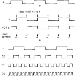
f Fig. 4 Behaviour offunctionsEach of which covers the store@-, , li, 8 r ) operation a Desired behaviour
b Behaviour of a load function and 11s support operailom c Behaviour of a 4-bit count function
d Behavlour of a 3-bit count runctlon e Behaviour or a 2-blt count function f Behaviour of a change states function 240
For example, a store(x-, , x, Sr) operation, whose behav- iour is shown in Fig. 4a, may be covered by following functions:
(i) A load function with support operation NOT(x, , x-,) and the value of a load control signal. The behav- iour of these logical entities is shown in Fig. 4h
(ii) A 4-bit count function with a system clock as its clock and unused operations store(0,-, , 0,, lr), store(0,-, , O,, 2r) and store(0,-, , O,, 4r) for the lower order output bits. The behaviour of a 4-bit count func- tion is shown in Fig. 4c
(iii) A 3-bit count function with 2r (a signal which changes its states every two clock cycles) as its clock and unused operations store(O,,-, , O,,-, 2r) and store(O,,-, , O,,, 4r) for the lower order-output bits. The behaviour of a 3-bit count function and its control signal is shown in Fig. 4d
(iv) A 2-bit count function with 4r as its clock and unused operations store(O,,-, , O,,, 4r) for the lower order output bit. The behaviour of a 2-bit count function and its control signal is shown in Fig. 4e
(v) A change states function of x every eight clock cycles repeatedly. Its behaviour is shown in Fig. 45 We have two substantially different node expansion stra- tegies for the A * algorithm in the program. One is gener- ating all possible child nodes. For example, while expanding a node which contains the operation store(x-, , x, Sr), all the child nodes that contain the above functions should be generated. Fig. 5 illustrates the generation of
the first two child nodes in the node expansion step. The second node expansion strategy generates only one child node for each type of function. The types of function that cover the above operation are load, change states and count. There is one function for function type load and change states, and several functions for function type count. We choose the most promising one from each type of these functions. Thus, if we have m possible functions which can be categorized into n types, we will have n branches from the node, one for each of the types. The most promising function is the one that contains at most one unused operation between two operations. For example, the above operation can be covered by a 4-bit count function only if there is a n operation store(b-, , b, 2r) (the second lowest bit). There is an unused operation (the third lowest bit) of the function between these two operations and another unused operation which is the lowest bit (the bit between the second lowest and nothing) of the count function.
The performance of the best-first search strategy should be compared with some other blind search stra- tegies to show their superiority. Comparison with the depth-first search strategy is meaningless. Since for every uncovered primitive operation, there is a function that
U store ( x - . , x, Er). [U]
U . NOT(x.
.
x-. 1A r0i
c:store(x-,cntl. x . ) . [cl
I
F : l o a d . - x - to x. [f]store (sig 2.. , s ~ g 2. 2r). store (si9 3.. , sig 3. lr). [a]
F . 4-bit count x. 519 1. sig 2. sig 3
I
[fl Fig. 5 Example ofnode expansioncovers it, applying the depth-first search strategy can always find a solution without backtracking. The solu- tion will be trivial functions, where each of them covers only one primitive operation or large functions that include too many unused operations. Which one of these extremely nonoptimum situations occurs depends on the order of selecting functions. We thus select the breadth- first search stragey for comparison and to show the superiority of our methods. All possible child nodes are expanded in each node expansion.
5.4 Timing analysis of primitive operations
While expanding a node, domain specific knowledge is employed to determine whether some of the uncovered operations can be covered by a function. The domain knowledge comes from two sources. The first one is the knowledge explicitly encoded in the representation of the function, i.e. certain primitive operations may match (with unification of variables) some covered operations in a function. The second one is the knowledge of per- forming timing analysis to match uncovered operations with those operations covered by a function. Here, timing analysis is defined as the task of exploring relationships among primitive operations. These relationships could include timing, input, output or others, e.g. the input/ output relationship of the change states function or the waveform regularity of the count function. Search for similarity is needed to accomplish this task.
Below, we give a detailed account o n how to exploit the timing relationships among a set of unrepeated store primitive operations to see if they can be covered by a count function.
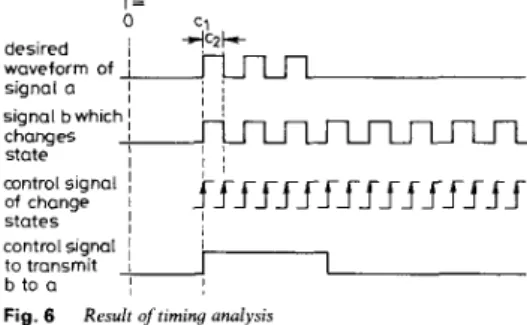
A count function is composed of several repeated change states functions; each of them may be represented by two primitive operations, namely store(a, c, b, t ) and NOT(b, , a,). On the other hand, each change states func- tion may also be represented by a single operation store(b-, c, b, t), where b- denotes the complement of h. If a signal changes its states every P clock cycles, and P is a power of 2, then the signal may be realised as one of the output bits in a count function. Furthermore, even if the timing parameter is a constant, it is still possible that operation will be repeated after certain intervals. Timing analysis is needed to find when such a repetition begins and ends. Then the timing parameter will take the format of
This indicates that the selected count function should be reset at time c1, and then repeated every c2 clock cycles. This, in turn, requires the use of supporting primitive operations to reset the count function and transfer the count output to the designated signal during the desired time interval. The behaviour of the count function and support operations are shown in Fig. 6 .
c, + c , r T = , , N I signal a
I
changes I state control signalI
of change 1 statesI
control signal I i to transmit1
b to a,
Fig. 6 Result oftiming analysis
IEE PROCEEDINGS, Vol. 136, P t . G , N o . 5 , O C T O B E R 1989
signal b which
I !
I ,
I 1 ;
f f
ffffff_rf
f
f
f
f
f
f
6 Examples
In this Section, we use a number of design examples to demonstrate the function abstraction subprocess and to compare the performance of the breadth-first search and the best-first search strategies.
6.7 Design examples
The first set of primitive operations to which the various search methods will be applied for comparison purposes are
store&, a, 16r) store(b-, , h, 8r) store@-, , c, 2r) AND@, b, c, , d,)
Its timing diagram is shown in Fig. 7. The functions selected by the three-node expansion strategies are identi- cal, i.e. a 5-bit count and an and function. The statistics of performance of each searching strategy are shown in Table 1, where the weight is that of uncovered oper- ations. Method 1 uses the A* algorithm and expands all possible child nodes. Method 2 uses the A* algorithm but expands only the most promising child nodes. Method 3 uses breadth-first search to find the first solution. In this table a hyphen is used to indicate that the program cannot find the result in reasonable amount of time and the j o b has to be aborted. The execution time is in ms.
clock
a b
C
d
Fig. 7 Timrny diagram
Table 1 :
Weight = 1 Weight = 2
Method Number of Expanded Time Number of Expanded Tme
expansion node expansion node
A' 4 43 600 2 21 31 7
A'. Meta- 5 27 384 3 15 250
planning
Breadth- 4 45 750
fwst
Next, the order of the above primitive operations is permuted as follows:
store(c-, , c, 2r) store@-, , b, 8 r )
store@-, , U, 16r) AND@, b, c, , d,)
Although different search strategies still arrived at the same set of functions, the performance statistics, as listed in Table 2, are different.
Table 2:
Weight = 1 Weight = 2
Method Number of Expanded Tlme Number of Expanded Time
expansion nodes expansion nodes
A' 4 43 600 2 21 300 A', Meta- 5 27 400 3 15 250 planning Breadth- 14 184 4650 first 241
The second experiment uses the set of primitive oper- ations of a sequence detector, which outputs a 1 to the output signal out, whereas the binary data stream from input signal x is 101 1. The set of primitive operations are
value(x, U , , t , ) value(x, U , , t ,
+ 1)
value(x, u 3 , t ,+
2) value(x, u 4 , t ,+
3) NOT(u,, 3 0s ANWui, 0 5 , 0 3 , u 4 9 , Out, t i+
3)When we assign 1 to the weight for uncovered oper- ations, the functions serial-to-parallel conversion, started at time t , , not, and and control signal generation, for starting the serial-to-parallel conversion function, will be selected. If the weight is set to 2, a different set of the functions loads, of signal x a t time t , , t ,
+
1, t ,+ 2 and
t ,+
3, and, not and control signal generation, for those load functions, will be selected. The statistics are com- piled in Table 3. In this example, the computation times of the two-node expansion method are comparable. This is because there is no store operation in the given set of primitive operations. Otherwise, there will be many dif- ferent instances of count function which may be selected. The difference in time of these two-node expansion methods is caused by the introduction of some store operations as support operations for selected functions. The breadth-first search strategy cannot find a solution in reasonable time before running out of computer memory ( 6 Mbytes allocated). This is because too many child nodes have to be generated to cover those transmit operations. In this case, permuting the order sequence of primitive operations does not improve the perfcrmince. Table 3:Weight = 1 Weight = 2
Method Number of Expanded Time Number of Expanded Time
expansion node expansion node
A* 295 1780 161717 10 57 1033
A*, Mela- 225 1450 110317 10 57 116
planning Breadth- -
first
6.2 Comparison of search strategies
The function abstraction program has been tested using 21 sets of compiled primitive operations to compare dif- ferent search strategies. The results are compiled and listed in Tables 4 to 8. Based on these tables, the follow- ing observations can be made:
(i) The number of functions selected seems to be inde- pendent of the number of compiled primitive operations. Instead, it depends more on the relevance among the set of primitive operations. If the primitive operations are closely related, usually fewer functions will be selected.
For example, there are only three primitive operations in case 2
store(a-, , a, t,)
value(c, rising, t,)
NOT(a,, w A B , t 2 )
Because these primitive operations are relatively indepen- dent, each requires a separate function to cover. In par- ticular, the functions selected are change states, control signal generation at time t , , control signal generation at time t , and not. The function control signal generation a t time t l is used to cover the support operation of function change states.
242
Table 4 : Numbers of initial primitive operations and found functions
A* algorithm Meta-planning Breadth-flrSt
of ops 1** 2 1 2 search 1 8 2 3 3 12 4 8 5 27 6 6 7 4 8 3 9 1 8 10 1 4 11 8 12 24 1 3 1 2 14 12 15 4 16 4 17 6 18 6 19 1 4 20 7 21 18 3 3 5 5 3 4 4 4 4 6 6 6 6 - 13 . . 3 3 3 3 2 1 1 1 1 1 3 3 4 4 1 3 4 3 4 2 3 3 3 3 1 1 1 1 1 5 2 5 2 1 1 1 1 1 1 1 1 1 1 1 1 1 1 4 4 4 4 3 4 4 4 4 3 1 1 3 3 1 1 1 3 3 1 7 4 7 4 4 4 4 4 - 1 4 . .
** Weight of uncovered operations Table 5 : Numbers of added omrations
A' algorithm Meta-planning Breadth-
1 2 1 2 first 1 0 0 2 0 0 3 0 0 4 . -5 0 4 6 2 2 7 2 3 8 0 0 9 0 0 1 0 0 0 11 0 4 1 2 0 0 13 0 0 ! 4 0 0 15 0 0 16 0 0 17 2 2 18 2 2 19 0 4 20 - - 21 0 0 0 0 0 0 0 0 - 0 0 4 2 2 2 2 0 0 0 0 0 0 0 4 0 0 0 0 0 0 0 0 0 0 0 0 0 0 0 4 - 0 0 0 0 27 2 6 4 0
Table 6 : Numbers of nodes expanded
A* algorithm Meta-planning Breadth-
1 2 1 2 first 1 3 3 7 5 205 2 6 4 6 4 3 6 6 6 6 4 . - - 13 5 5 4 5 4 765 6 1 1 1 1 1 7 165 3 62 4 1 8 5 4 5 4 3 9 3 3 3 3 10 1 1 1 1 1 11 5 2 5 2 1 2 2 2 2 2 13 1 1 1 1 1 14 1 1 1 1 1 1 5 4 4 4 4 13 16 4 4 4 4 1 9 17 1 1 4 4 1 18 1 1 4 4 1 1 9 7 4 7 4 20 - ~ - 1 4 21 5 5 5 5
Table 7 : Numbers of generated nodes 4 5 6 7 8 9 10 11 12 13 14 15 16 17 18 19 20 21 A* algorithm 1 2 55 55 15 10 48 48 55 41 7 7 2891 55 23 17 37 37 24 24 43 25 60 60 20 20 20 20 21 21 27 27 37 37 37 37 82 55 56 56 Meta-dannina 1 2 47 39 15 10 48 48 - 122 55 41 7 7 334 22 23 17 37 37 24 24 43 25 60 60 20 20 20 20 21 21 27 27 24 24 24 24 82 55 - 121 56 56 Breadth first 5465 441 1 2 13 1 8 18 10 20 87 122 3 12
Table 8: Execution time
A' algorithm Meta-planning Breadth. 1 2 1 2 first 1 1000 2 150 3 1483 4 -5 2284 6 133 7 490967 8 250 9 10 11 12 13 14 15 16 17 18 19 20 21 1500 667 933 3084 550 634 21 6 383 600 100 1983 1917 1017 833 667 1512700 150 183 117 - 1567 1733 1783 - - 4183 - 1900 2400 1967 1314550 100 150 150 167 1050 9600 383 167 184 217 183 166 1500 1367 1533 - 700 717 733 600 583 734 450 - 3017 3200 3266 - 567 833 817 317 633 800 817 567 183 217 200 1383 367 400 400 2683 750 384 350 100 900 483 516 283 1433 2367 1633 - 3767 - 1650 1800 1783 -
As another example, there are 24 primitive operations in total in case 12
input(ld, rising, t value(in, U,,, t ,
+
i - 1)input(st, rising, t,) for t, 2 t,
+
5 transmit(vIi,, outi, t 2 ) input(ld, rising, t,) value(in, u Z i , t ,+
i - 1) input(st, rising, t,) transmit(u,,, , outi, t4) for i = 1 to 5 for t, 2 t ,+
5However, since these primitive operations are highly related, one function only, a 5-bit serial-to-parallel con- version function, will be sufficient to cover all these primitive operations
(ii) The breadth-first search is computationally too costly to be a practical search strategy. In our experi- ments, whenever there are more than four functions to be selected, the breadth-first search process had to be aborted due to excessive usage of C P U time. Instead, the planning technique seems to have better search efficiency in cases where more sequential operations are needed, such as cases 4, 7, 17, 18 and 20. Note that in cases 4 and IEE PROCEEDINGS, Vol. 136, Pt G , N o . 5 , O C T O B E R 1989
20, it helped solve the problems which even the A* algo- rithm failed to do. For example, in case 4, the set of primitive operations are
store(a-, , a, 1) store@-, , a, 4) store@-, , a, 7) store(a-, , a, 10) store(a-, , U, 12) store@-, , a, 14) store(a-, , a, 16) store(a-, , a, 18)
A timing analysis is carried out to explore functions which implicitly cover this set of primitive operations. The only results found are three change states functions at time, 1, 4 and 7, a 4-bit count function started at time IO and stopped at time 18, a gate function which trans- mits outputs of the count function to signal a, a set func- tion and a reset function of a signal which enables operations of the count function, control signal gener- ation functions at time 1, 4, 7, 10 and 18 and a clock of the count function
(iii) Increasing the weight of uncovered primitive oper- ations usually cuts the execution time. It also frequently results in a fewer number of functions being selected, as it favours the use of functions that cover more primitive operations. But these benefits come a t a price: a larger weight of uncovered operations discourages the search direction from backtracking to a higher level node in the search tree where a better solution may reside. In other words, using larger weights o n the uncovered functions is a greedy heuristic which improves the search efficiency at the risk of sticking in a local minimum, and therefore missing the globally optimised solution. For example, in case 8, where three primitive operations are given
transmit(c, , d, t , ) transmit(b, , d, t ,
+
1)Value(a, c, t l )
If the weight of uncovered operations is set to 1, two gate functions and a control signal generation function will be selected. However, if it is set to 2, one more load function will be selected which clearly is a n inferior solution
(iv) In several cases, such as 6, 7, 13, 14, 17 and 18, the breadth-first search strategy arrived at solutions faster than other methods. This is because, in these cases, only one function is selected. With the breadth-first search strategy, the process of node expansion will be halted once the first feasible solution is found. Clearly, this may result in inferior solutions. O n the other hand, with other methods, the cost of all unexpanded nodes will be com- pared after node expansion. At the cost of a few more node expansion iterations, often a better solution can be obtained. For example, the set of primitive operations in case 7 are
store(h-, , b, 2r) store(e-, , e, 8r) store(d-, , d, 128r) storeCf-,
,L
512r)Using breadth-first search, a 10-bit count function is found to cover these operations. Using the A* algorithm, the result contains a 3-bit count function controlled by the system clock and a 2-bit count function, together with a control signal generation function. Using the plan- ning technique, the result includes two 2-bit count func- tions and two control signal generation functions. 243
Although the number of functions selected is larger using the latter two methods, they include less unused primitive operations and may lead to a more economical design.
(v) The performance of the breadth-first search is very much dependent on the order in which the set of primi- tive operations is arranged. T o see this point, the test data sets 13 and 14, 15 and 16, as well as 17 and 18, are, respectively, three pairs of data sets; each has the same set of primitive operations but with different orders. It turns out that the execution time using the breadth-first search has much larger variations than that of using the other two methods.
For example, the set of primitive operations in both cases 15 and 16 are
transmit(b, c1, c,)
transmit(b, cz , e,)
A N W , , a 2 , cl.) AND(a,, a2-, c Z J
Using the breadth-first search method, it takes 1383 ms to compute case 15 which yields two and functions and a I-line-to-4-line demultiplex function, and 2683 ms to
compute case 16 which yields the same set of functions. O n the other hand, with the two other methods, the dif- ferences are not that significant; two gate functions and two and functions are selected
(vi) In some cases, the number of node expansions using the planning method may be greater than that of the A* methods. Nevertheless, the number of generated nodes of the planning method is always less than or equal to that of A* methods. This is because the planning method prunes the more unfeasible nodes during the search process.
7 Conclusion
We have reported the result of using heuristic search and a simple meta-planning technique of artificial intelligence in a minimisation problem - function abstraction of digital circuit design. There are two minimisation sub- processes in our automatic design system. The first one is function abstraction which finds the functions the target system performs. The other one is structure implementa- tion which realises the functions by structural modules. Adding the function abstraction subprocess is a distin- guished feature of the system. It finds the essence of the target behaviour rather than binds functions in the spe- cification directly to function modules. This provides more opportunity for performing minimisation. We have coded this subprocess using PASCAL on VAX 11/780.
Experimental results have shown the heuristic search eff- ciently reduces the huge design space. Adding meta- planning the search process usually leads to the same solution but in a shorter time.
We are designing better heuristic functions and more elaborated meta-planning techniques in the minimisation step as an effort to get better designs in a shorter time. We are also applying the heuristic search and meta-
planning techniques on the other minimisation step - structure implementation. The interface between these two subprocesses to resolve their interaction is also a n important topic.
8 Acknowledgment
Y.H. Hu is supported by the National Science Founda- tion under contract MIP-8896111.
9 References
I MrCLUSKEY, E.J. Jr.: ‘Minimization 01 Boolean functions’, Bell Syst. Tech.J., 1956,35,(6),pp. 1417-1444
2 BRAYTON, R.K., HACHTEL, G.D., McMULLEN, C.T., and
SANGIOVANNI-VINCENTELLI, A.L.: ‘Logic minimization algo- rithms for VLSl synthesis’ (Kluwer Academic Publishers, 1984) 3 HONG, S.J., CAIN, R.G., and OSTAPKO, D.L.. ‘MINI: a heuristic
approach for logic minimization’, IEM .I. Res. Dev., 1974, 18, (5). pp.
443458
4 DARRINGER, J., BRAND, D., GERBI, J.V., JOYNER, W.H. Jr., and TREVILLYAN, L.. ‘LSS: a system for production logic synthe- sis’, I E M J. Res. Dev., 1984, 28, (9, pp. 537-545
5 DE GEUS, A.J , and COHEN, W.: ’A rule-based system for opti- mizing combinational logic’, IEEE Des. Test Cornput., 1985, 2, (4),
pp. 22-32
6 KOWALSKI, T.J.: ‘An artificial intelligence approach to VLSI design’ (Kluwer Academic Publisher, 1985)
7 KOWALSKI, T.J., and THOMAS, D E : ’The VLSI design automa- tion assistant: an 1BM system/370 design’, IEEE Des. Test Cornput.. 1984, 1, ( I ) , pp. 6&69
8 GRANACKI, J , KNAPP, D., and PARKER, A.: ‘The ADAM advanced design automation system: overview, planner and natural language interlace’. Proceedings of 22nd Design Automation Con- ference, Las Vegas, NV, USA, June 1985, pp. 727-730
9 KNAPP, D.W., and PARKER, A.C.: ‘A design utility manager. the ADAM planning engine’. Proceedings of 23rd Design Automation Conference, Las Vegas, NV, USA, June 1986, pp. 48-54
I O MITCHELL, T.M., STEINBERG, L.I., and SHULMAN. J.S.: ‘A
knowledge-based approach to design’, IEEE Trans., 1985, PAMI-7,
( 5 ) . pp. 502-510
1 I BREWER, F.D., and GAJSKI, D.D.: ‘An expert-system paradigm lor design’. Proceedings of 23rd Design Automation Conlerence, Las Vegas, NV. USA, June 1986, pp. 62-68
12 SUBRAHMANYAM, P.A.: ‘Synapse: an expert system for VLSl design’, IEEE Trans. Cornput., 1986, 19, (7), pp. 78-88
13 WU, J.-G., HO, W.P.-C., HU, Y.H., YUN, D.Y.Y., and PARNG, T.M: ’A model-based expert system for digital systems design’,
Proc. Soc Photo-Opt. Instrum. Eng., (USA), Applications of Artijicial Intelligence V , May 1987,786, pp. 12-19
14 MCFARLAND. M.C: ‘Using bottom-up design techniques in the synthesis of digital hardware from abstract behavioral descriptions’. Proceedings of 23rd Desian Automation Conference. Las Veeas, NV, USA,June, 1986, pp 474-480
15 W U , J - G , HO, W P - C , H U , Y H , Y U N , D Y Y , P A R N G , T M ,
and HSU, C . C . . ‘Multiple representations lor automatic design of digital systems’. International Symposium on VLSl Technology, Systems and Applications, Taipei, Taiwan, ROC, May 1987, pp. 12G128
16 WU, JLG.. HO, W.P.-C., HU, Y.H., YUN, D.Y.Y., and YU, H.J.: ‘Function search from behavioral description of a digital system’. Proceedings of 24th Design Automation Conference, Miami, FL, USA, June 1987, pp. 574-579
17 RICH, E.: ‘Artificial Intelligence’ (McGraw-Hill, 1983)
18 STEFIK, M.: ‘Planning and meta-planning (MOLGEN: part 2)’.
Art$ Intell., 1981, 16, (Z), pp. 141-169
19 SACERDOTI, E.D.. ‘The nonlinear nature of plans’. Proceedings of the 4th International Joint Conlerence on Artificial Intelligence,
1975, pp. 20f-214