Finite element analysis and optimization on springback
reduction
I-Nan Chou, Chinghua Hung
*Department of Mechanical Engineering, National Chiao Tung University, 1001 Ta-Hsueh Road, Hsinchu, Taiwan, ROC
Received 9 October 1997
Abstract
Several springback reduction techniques used in the U-channel bending processes were analyzed with the finite element method, which included arc bottoming, pinching die, spanking and movement techniques. The relationship between the amount of springback and the forming parameters in each technique was first established through finite element simulations, and then the optimization analysis was coupled with the finite element analysis to find the optimum forming parameters for each springback reduction technique.
1998 Elsevier Science Ltd. All rights reserved. Keywords: Springback; Finite element method; Optimization
1. Introduction
1.1. Springback
In the bending processes, when the forming forces have been removed, the metal tries to return to its original shape and results in a phenomenon called “springback”. Springback is a function of both the material properties and die configuration; the greater the strength and the lower the elastic modulus of the material, and the larger the bend radius and die gap, the greater the spring-back will be [1]. Minimizing springspring-back is one of the most troublesome problems in die design. There are some methods to compensate springback in practice. They can be classified into two main categories: the traditional methods and the “double-bend” technique.
* Corresponding author. Fax:+886-35-720-634; E-mail: chhung@cc.nctu.edu.tw 0890-6955/98/$—see front matter1998 Elsevier Science Ltd. All rights reserved. PII: S 0 8 9 0 - 6 9 5 5 ( 9 8 ) 0 0 0 3 1 - 5
1.2. The methods in springback reduction 1.2.1. The traditional methods
Extensive work has been done in the past to reduce springback. Springback may be counteracted by overbending, by stretch forming, by arc bottoming or by pinching die techniques. For the reason of fewer constraints on die design, arc bottoming and pinching die techniques are practi-cable choices on compensating springback [2].
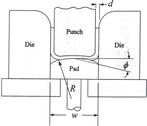
Arc bottoming is a useful method to counteract the effect of springback. The principle of the arc bottoming method is to use the springback caused by an arc bottom of the die to compensate the springback at the side wall. A simple arc bottoming operation is shown in Fig. 1.
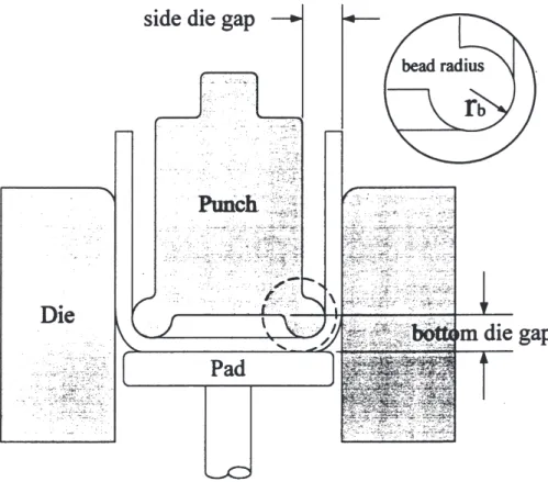
A pinching die technique is also commonly used to reduce the springback in practice. In this method, springback can be eliminated by a beaded punch that pinches the metal with two circular beads, the diameters of which are slightly larger than the metal thickness. Fig. 2 illustrates the pinching die technique method used in U-channel bending.
1.2.2. The “double-bend” technique
The basic concept behind the “double-bend” technique is to bend the channel walls twice at different sites. The double-bend technique proposed by Liu [3] has been used as the basis for many bending operations that have been proven experimentally to be effective in reducing spring-back [4]. Shu [5] has successfully used the finite element method to simulate some of the
Fig. 2. The pinching die technique.
bend” techniques and obtain a good agreement with Liu’s experimental data. In our research, we try to study two other variations of the double-bend technique, so-called “spanking” and “move-ment”.
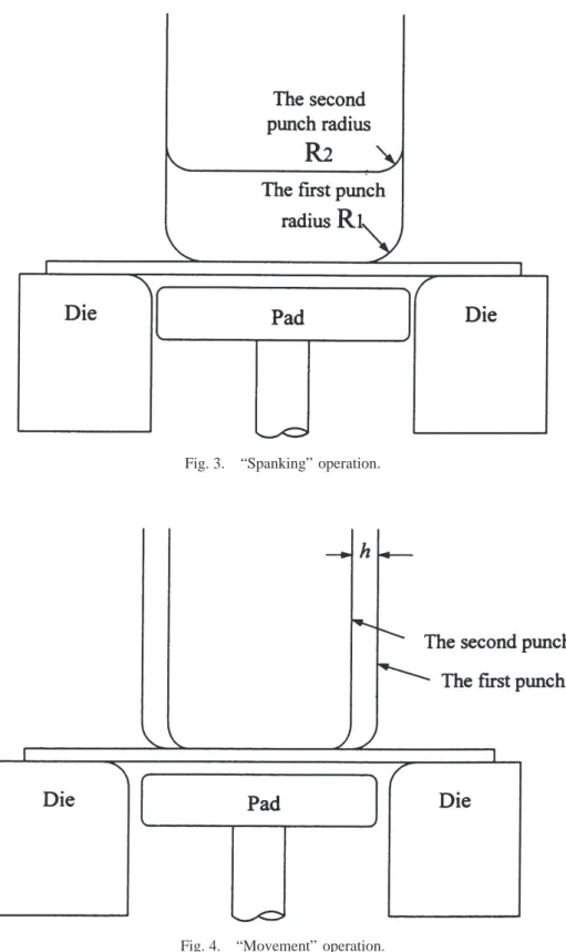
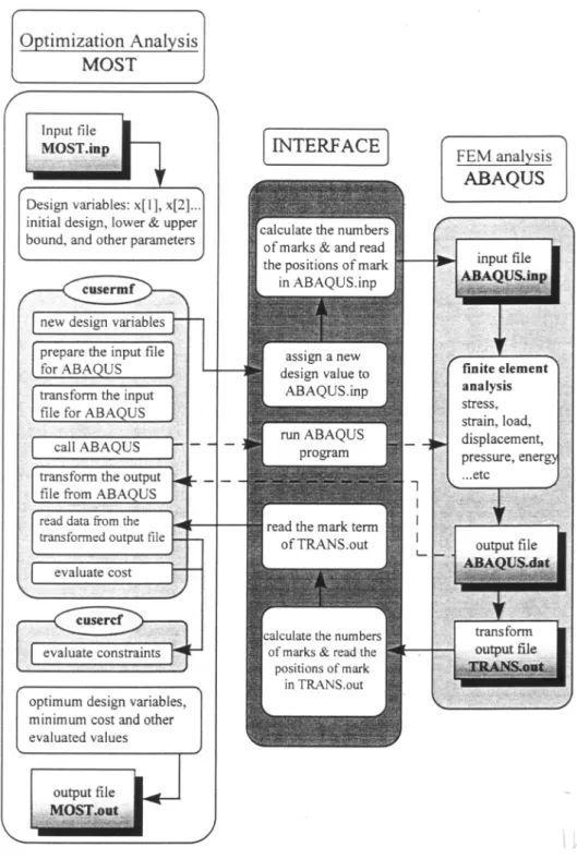
The spanking operation is used to reform parts which have already had their major contour formed in the conventional manner [6]. The spanking punch may appear to be very similar to the original forming punch but with a smaller radius. When restriking the preformed channel, the spanking punch can overcome the original springback. The spanking operation is shown in Fig. 3. In the movement operation, two punches of slightly different widths are employed; one punch is used to preform channels with slanted walls, and the other restrikes the walls to reduce the slant, as shown in Fig. 4. The second punch is always narrower than the preform punch. That is, movement operation is the same as the “reducing” double-bend technique proposed by Liu.
1.3. Scope of the research
Although there exist several methods for overcoming springback, it’s still difficult for a designer to design sheet-metal forming processes that totally eliminate the springback problem. We plan to use the finite element method to simulate the processes of the above four techniques used on springback reduction and evaluate their effectiveness on springback control. Furthermore, the
Fig. 3. “Spanking” operation.
optimum forming parameters for each technique will be found by coupling the optimization method with the finite element analysis to make this research more complete.
2. Finite element and optimization program
The finite element program used in the research is ABAQUS/Standard, which is a commercial program available from Hibbitt, Karlsson and Sorensen, Inc. of the United States [7]. The appli-cation field for ABAQUS is large, particularly for plastic deformation and manufacturing pro-cesses. In this research, one optimization program will conjoin with the finite element program in seeking the optimum forming parameters. The cost function in most practical problems may be represented as implicit for the relevant design variables, therefore an optimization program named MOST [8] suitable for implicit form problems is used in this research.
In this research, the program MOST serves as the backbone of the analysis system. The entire process can be accomplished with the aid of a program to serve as an interface between MOST and ABAQUS. The overall structure of the optimum design program is shown in Fig. 5. When MOST is executed, the interface program will run ABAQUS with the given forming parameters. The cost function and constraint functions will be evaluated from the output data of ABAQUS. The cost function gradient that is found will then be used to determine the searching direction and step size and thus obtain the optimum solution.
3. The analysis procedure and optimum design
3.1. Materials and finite element mesh
HS110 and AKDQ steel sheets are selected as the materials of the workpiece in our study. The strain hardening of materials in analysis is modeled by an isotropic hardening rule which is widely adopted in predicting purely elastic springback. The dimensions of the specimen are: blank size, 76 × 152 mm; material thickness, 0.8 mm; punch width, 29 mm; die entrance radius, 6.35 mm; load of pressure pad, 600 nt; and intended bending angle, 90°.
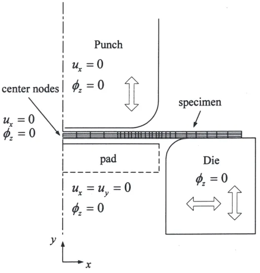
For reasons of symmetry in U-channel processing, we can reduce the 3D problem to a 2D problem by assuming a plane-strain condition. The mesh and boundary conditions used in this simulation are represented in Fig. 6.
3.2. Description of the optimization program
The cost function selected is the springback angle in the optimum design for a springback reduction problem. This cost is an implicit expression of design variables (the design variables of various cases will be described in the following section, respectively). So, we can only calculate the cost from the output data of the finite element analysis. The cost function can be defined as follows:
Fig. 6. Mesh and boundary conditions.
where f is the apparent springback and is the angle between two side walls of the product. f
ⱖ 0 can be regarded as a constraint and is employed in order to prevent the springback from
being overcorrected, resulting in a “toe-in” configuration.
In order to avoid fractures on the bending sites, we stipulate that the effective stress of the elements during the forming processes must be less than a certain safe value for each kind of material. This constraint is adopted in all cases.
3.3. Cases for analysis with the traditional methods 3.3.1. Arc bottoming method
The springback at the arched bottom of a U-channel metal sheet can compensate the springback on the side walls. The radius of the arched pad, R, can be used to control the compensation for springback. Theoretically, a smaller value of R can reduce a greater springback angle. Usually,
a very large value of R will be chosen in order to prevent plastic deformation around the bottom of the metal sheet. For the purpose of controlling very small variations between large values of
R, we can define a correction angle as follows:
= 1
2 sin
−1
冉
w2R
冊
, (2)where is the angle between horizontal and the chord across the tip and side point on the arched pad, and w is the width of the pressure pad (see Fig. 1).
Another forming parameter is the die gap. The die gap usually plays an important role in springback control in the literature. In this case, two chosen values of die gap, 0.84 and 0.9 mm, will be adopted in the finite element simulation. These two forming parameters, the correction angle and die gap, are taken as the design variables in the optimum design.
3.3.2. Pinching die method
The basic concept of the pinching die method is shown in Fig. 2. A bead (or beads) will be placed on the punch to locally compress the metal to provide the residual stress which can com-pensate the springback. Large bead radii and small die gaps should not be used to avoid fracture of the sheet metal. The suggested value of bead radius, rb, is half the thickness of the sheet metal
[2]. With the thickness of our workpiece of 0.8 mm, we chose the value of rb to vary from 0.3,
0.35, . . ., to 0.5 mm for the finite element simulation.
The side die gaps and bottom die gaps are very important forming parameters in this manufac-turing process. In our research, the bottom die gap remained as fixed and the side die gap was chosen as a design variable. The bead might pinch the metal too much and result in fractures if the side die gaps are too small. Three various values of side die gaps, 1.1, 1.2 and 1.3 mm, were combined with various rbs for simulation. On the other hand, we checked the effective stress of
elements pinched by the bead to prevent fracture. The results of the finite element analysis can be taken as the upper and lower bound for the optimum design variables, and thus the number of iterations in the optimization program can be considerably decreased. The bead radius and side die gap are also chosen as the design variables in the optimum analysis.
3.4. Cases for analyses with the double-bend methods 3.4.1. Spanking technique
Spanking is a variation in the double-bend technique. It uses the effect of changing punch radius in the second operation (to a smaller one) to reduce total springback. After the first operation of the U-channel bending process using a punch with radius R1, a second punch with radius R2 is
used to restrike the same workpiece in the following operation (see Fig. 3). A spanking ratio, C, is defined as,
C = R1− R2 R1
. (3)
In the finite element simulation, values of spanking ratios are chosen as 0.0, 0.25, 0.5 and 0.75 and the value of R1 is kept at 6.36 mm. The die gap is treated as another important variable in
this process operation. Three chosen values of die gap for simulation were 0.8, 0.84 and 1.28 mm. Both the die gap and spanking ratio were taken as design variables in the following opti-mum design.
3.4.2. Movement technique
Movement is defined as the distance between two different bending sites. In Shu’s study, several situations from the double-bend technique were investigated, such as restrike with a narrow punch, restrike with a wider punch, and the effect of bottom die gap on springback. In cases of the movement technique, we focused on restriking with a narrow punch. Movement can be defined as half the distance between the width of the first punch and the second, that is:
h= 1
2(Wp1−Wp2), (4)
where Wp1 is the width of the first punch, and Wp2 is the width of the second one (see Fig. 4).
Movement varies from 0.0, 0.5, . . ., to 4.0 mm for the finite element analysis. In our case, the value of Wp1 and the die gap were kept the same at 29 mm and 0.84 mm, respectively. The
other forming parameter is the punch radius, rp, and three values, 2, 4 and 8 mm were chosen
for simulation. In the optimum design, these two forming parameters, movement and punch radius, are simultaneously taken as the design variables in our research.
4. Results and discussion
4.1. Results of finite element analysis on the traditional methods 4.1.1. Arc bottoming method
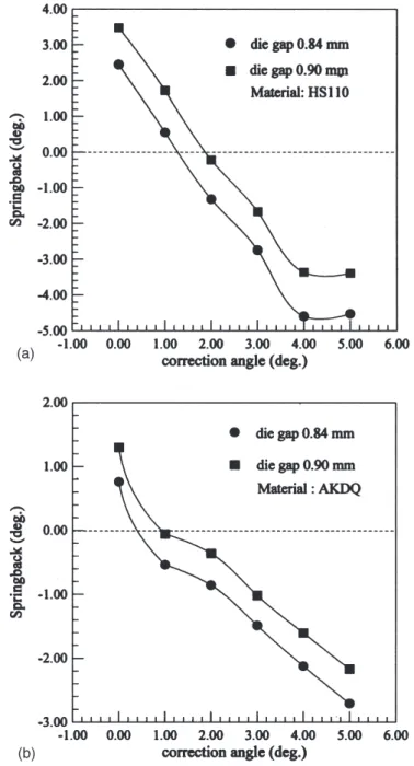
Fig. 7 shows the effects of the correction angle and die gaps on springback. For both materials, HS110 and AKDQ, the results show that springback decreases with an increasing correction angle (). On the other hand, larger die gaps always cause smaller springback.
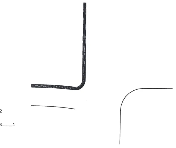
The slopes of springback curves vary more around two special points which are approximately located at correction angles 4° and 1° for HS110 and AKDQ materials, respectively. From the deformed configuration (see Fig. 8), we can see that plastic deformation occurred at the bottom of the U-channel with a larger correction angle. As a result, the arc bottoming method no longer provided enough springback to compensate the springback at the side walls. The effects of plastic deformation at the arched bottom will result in residual stress after the die force is released. Improper residual stress in sheet-metal products should be avoided in practice. The ranges of forming parameters that could result in an “arched bottom” will be taken as infeasible regions in the following optimum design.
4.1.2. The pinching die method
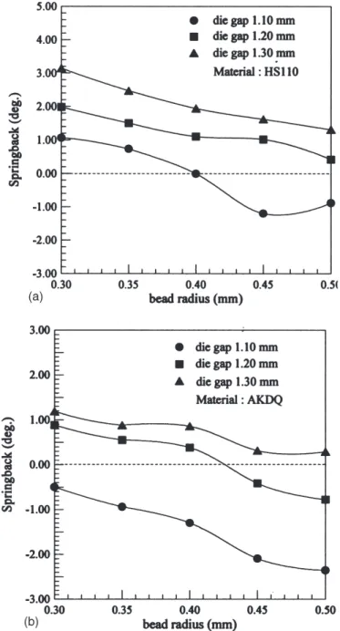
The pinching die method can increase compressive stress at the bending point and thus reduce the springback. The results of finite element analysis are shown in Fig. 9. From the data of stress,
Fig. 7. Results of Finite Element analysis on arc bottoming.
we found that small side die gaps (i.e., 1.10 mm) would result in failure because the effective stress where the beads pinched was larger than the ultimate strength of the material. In most cases, the effective stress is very close to the ultimate strength at the pinched point. Generally speaking, this method is not as powerful as the arc bottoming method because larger side die gaps should be applied to prevent failure in the bending process.
Fig. 8. The result of arc bottoming with a larger correction angle.
The general trend of the springback curve tends towards negative with increasing bead radius. It can be realized that large bead radii provide more pinching-in because the bottom die gaps are fixed. On the other hand, the smaller side die gaps also provide a good situation for pinching and the springback can be reduced. The effect of bead radius is not so obvious as we presumed because we applied larger side die gaps for the prevention of fracture. In contrast, the effect of die gap is visible when a larger bead radius was applied, especially for AKDQ steel.
4.2. Results of finite element analysis on the double-bend technique 4.2.1. Spanking technique
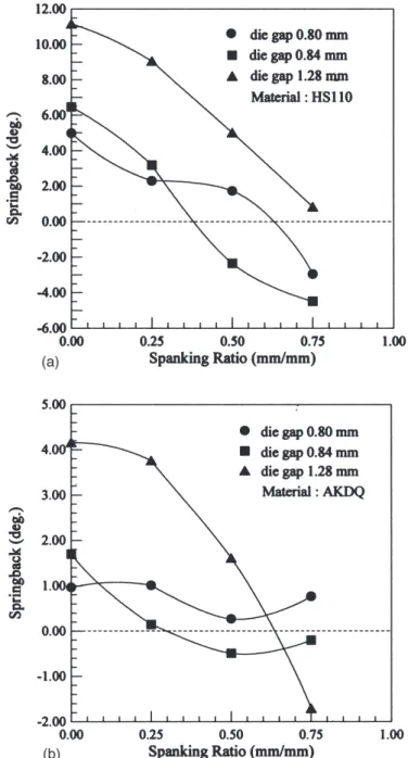
The spanking technique used in this research is one of the double-bend techniques which pro-vides a severe bend at the second punching process. Theoretically, a larger spanking ratio (C) can result in more springback reduction. As shown in Fig. 10(a), the values of springback for HS110 steel decrease effectively with an increasing spanking ratio. In Fig. 10(b), the springback reduction for AKDQ steel is not visible in the cases with smaller die gaps, 0.80 and 0.84 mm.
Fig. 9. Results of Finite Element analysis on the pinching die method.
Cases with die gap of 1.28 mm show the largest effectiveness of springback reduction for both materials.
4.2.2. Movement technique
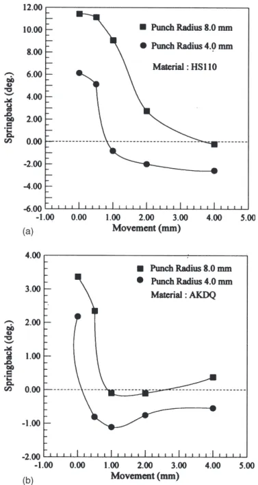
The results of finite element simulation on the movement technique are shown in Fig. 11. The curves of springback tended to go down rapidly with smaller values of movement. In Fig. 11(a),
Fig. 10. Results of Finite Element analysis on the spanking technique.
the springback reduction provided from larger movement values was negligible. For AKDQ steel, this technique nearly had no effect on springback reduction when the values of movement were larger than 1.0 mm. When the first punch load was released, the residual stress still remained compressive at the first-bending point. Therefore, it can be realized that restriking around the first-bending point (a smaller movement value was applied) is more effective on springback
Fig. 11. Results of Finite Element analysis on the movement technique.
reduction than restriking away from this point. For the second parameter, punch radius, it is presumed that a smaller punch radius will get a smaller springback for sheet-metal bending.
4.3. Results of optimization
After individual analysis for the chosen parameters in the above four methods on springback reduction, we used an optimization program MOST to find optimum designs for springback reduction. During the analysis, the results of optimization also showed the sensitivity of each para-meter.
1. Arc bottoming: In order to prevent the severe arched-bottom in the arc bottoming method, a new constraint with which the nodes at the bottom should keep in a line with an error of 0.05 mm, was adopted in the optimization program. In the final design for HS110, the correction angle () is 1.673° and the die gap (d) is 0.868 mm at the optimum point, where springback is 1.432 × 10⁻²°. For AKDQ steel, the optimum values of and die gap d are 0.912° and
0.909 mm, respectively, and the springback of final design is 4.77×10⁻³°. The contour surfaces
of springback with respect to these two design variables for HS110 and AKDQ are shown in Fig. 12. This figure shows that the springback is almost equally sensitive to both parameters. 2. Pinching die method: To avoid severe stress concentration, the Mises stress should be con-strained to less than the ultimate strength of materials, 905 MPa and 475 MPa for HS110 and AKDQ, respectively. The optimal bead radius (rb) and side die gap (d) of the pinching die for
HS110 are 0.508 mm and 1.184 mm, respectively, and the resulting springback is 1.028 × 10⁻⁷°. For AKDQ, optimal r
b, d and resulting springback are 0.504 mm, 1.244 mm and 5.782
× 10−2°, respectively. Fig. 13 shows the contour surfaces for the pinching die method.
Spring-back is less sensitive to bead radius, except around the region of 0.45 mm bead radius for HS110.
3. Spanking technique: Fig. 14 is the contour surface plot of springback against spanking ratio (C) and the die gap (d). Springback is much more sensitive to spanking ratio than to the die gap. The value of C is 0.409 and d is 0.80 mm at the optimum point for HS110, where springback was 1.061 × 10⁻²°. The optimization results of AKDQ are 0.282 mm, 0.84 mm
and 5.09 × 10⁻³° for the value of C, d and springback, respectively.
4. Movement technique: The optimum values of movement (h) and punch radius (rp) for HS110
are 0.502 mm and 2.0 mm, respectively. The springback at the optimum point for HS110 is 1.432 ×10⁻²°. For AKDQ steel, 1.577 mm for h and 2.67 mm for r
pare the optimum values.
The resulting springback is 1.03 ×10⁻⁷°for AKDQ. The contour surface plot is shown in Fig.
15. We found that springback was not very sensitive to these two parameters, except in the region where a smaller movement value was applied for HS110.
4.4. Discussion
As shown in finite element analysis, the traditional methods are effective in springback reduction. The arc bottoming is very powerful but the arched bottom will occur at large correction angles, especially for AKDQ steel. The plastic deformation at the arched bottom should be avoided in practice because the residual stress could cause fracture. In the pinching die method, the effect of the side die gap is more significant than that of the bead radius. Conclusively, this method is not ideal in reducing springback because it could cause severe stress concentration at the pinched point and probably affect the reliability of sheet metals if post-forming is necessary.
Fig. 13. Contour surfaces for the pinching die method.
The stress and strain contours resulting from double-bend techniques are more homogeneous than those from traditional methods because a separate second bend was applied. Spanking ratio is an influential parameter in the spanking technique and can reduce springback efficiently. The movement technique is only effective when small movements are applied. Larger movements may result in larger springback as shown from the results of Liu’s experiment and Shu’s simulation.
Fig. 15. Contour surfaces for the movement technique.
It is easy to realize that more than one optimal point exists in multi-design-variable optimiz-ation. The contour surface plots are very useful to observe the sensitivity of each design variable in each method of springback reduction.
5. Conclusions
Conclusions of this research are as follows:
1. The proposed methods in our research can indeed reduce springback under some conditions. Generally, the double bend techniques are more powerful and safer than traditional methods.
2. Results of our research for optimization provide acceptable sets of design variables, which show that the use of coupled finite element optimization analysis is both practical and efficient in solving the problem of springback control.
3. More reasonable design variables, such as pad pressure, punch radius or entrance die radius can be considered in future study.
4. This research shows an example of using the coupled technique with MOST and ABAQUS programs in solving metal forming problems, further applications in other engineering prob-lems are expected.
Acknowledgements
The authors would like to thank the National Science Council of R.O.C. for grant NSC86-2212-E-009-015, under which the investigation was possible. The authors would also like to thank Professor C.H. Tseng for offering the optimization computer code.
References
[1] N.M. Wang, Efficiency in sheet metal forming, Proc. 13th Biennial Congress IDDRG, Melbourne, Australia (1984). [2] G. Sachs, Principles and methods of sheet-metal fabricating, Reinhold Publishing Co., USA (1956).
[3] Y.C. Liu, US Patent No. 4,373371, February (1983).
[4] Y.C. Liu, Springback reduction in u-channel—“double-bend” technique, J. Appl. Metalworking 3 (1984) 148–156. [5] J.-S. Shu, C. Hung, Finite element analysis and optimization of springback reduction: the “double-bend” technique,
Int. J. Mach. Tools Manufact. 36 (4) (1996) 423–434.
[6] D.F. Eary, E.A. Reed, Techniques of Pressworking Sheet Metal, Prentice-Hall, USA (1958). [7] Hibbitt, Krlsson and Sorensen, Inc., ABAQUS Manual (1996).
[8] C.H. Tseng, W.C. Liao, T. Yang, MOST User’s Manual Version 1.0, Technique Report No. AODL-91-01, National Chiao Tung University, ROC (1991).