國
立
交
通
大
學
資訊科學與工程研究所
博士論文
一套適用於無線車輛通訊網路研究的網路與交
通模擬器
A Network and Traffic Simulator for Wireless
Vehicular Communication Network Research
研 究 生 : 周智良
一套適用於無線車輛通訊網路研究的網路與交
通模擬器
A Network and Traffic Simulator for Wireless
Vehicular Communication Network Research
研 究 生 : 周智良 Student : Chih-Liang Chou
指導教授 : 王協源 Advisor : Shie-Yuan Wang
國 立 交 通 大 學
資訊科學與工程研究所
博士論文
A Dissertation
Submitted to Department of Computer Science College of Computer Science
National Chiao Tung University in partial Fulfillment of the Requirements
for the Degree of Doctor of Philosophy
in
Computer Science
July 2009
一套適用於無線車輛通訊網路研究的網路與交通模擬器
學生:周智良 指導教授:王協源教授
國立交通大學資訊工程學系(研究所)博士班
摘 要
當智慧型運輸系統的概念對全世界展示出其改善交通運輸品質與效率的潛 力後,工業界與學術界對於可應用於智慧型運輸系統的技術一直都抱持著高度的 興趣。直到現今,智慧型運輸系統已經發展成為一個非常熱門的研究領域,也已 經有許多在日常生活中的實際應用,例如常見的車上廣播電視、車上衛星導航、 車上電子自動收費系統等等,這些應用不僅為智慧型運輸系統的成功做了見證, 相信在未來日子裡,更多相關領域的研究也將陸續地投入去發展更新穎與便利的 應用。 智慧型運輸系統的目標,是利用將資訊與通訊科技(例如各式各樣的無線網 路技術)加到基礎運輸建設與車輛上,以達到改善車輛與行人安全、增加運輸效 率、提供車上娛樂等目的。舉例來說,透過車輛間互相交換自己的地理位置、移 動方向與移動速度的訊息來達到碰撞的預警,透過參考及時路況的車輛導航系統 來降低行車時間與燃料消耗,透過電子式自動收費系統來增加行車的流暢性,透 過數位電視廣播提供給車上乘客各種的視聽娛樂,以及車上的網際網路連線服務 等等都是這一類型的應用。 可以肯定的,任何應用在實際部署以提供服務之前,一定得經過某些程度的 測試來證實其可行性。而對於測試上述類型的應用,在實際的道路環境中做測試 通常是為了獲得可信的測試結果所必須的。然而,這樣的測試有時會需求大量的 車輛與人力,有時會需要能穩定控制的車輛駕駛路徑等等,這些特性可能會需要 昂貴的花費,或是使測試人員在測試的過程中處於有潛在危險的環境裡,更甚 者,由於非測試人員所駕駛的其他車輛並不會配合測試而做出特定的移動方式, 某些要求特定車輛相對移動方式的測試在實際的道路環境中是很難準確控制 的。有鑑於此,為了消除或減輕以上所提到在測試中所可能遭遇的困難,利用模 擬工具便成為一種可以取代或是輔助實地測試的一種選擇。 在此論文中,我們將介紹一套適用於無線車輛通訊網路研究的網路與交通模 擬器。此模擬器整合了網路通訊協定的模擬能力與車輛移動行為的模擬能力。前 者包括 TCP/IP、UDP/IP、IEEE 802.16e、IEEE 802.11p 等等適用於車輛網路的 通訊協定,後者包括車輛於道路網路上的移動行為、車輛對於紅綠燈號誌的反 應、車輛的跟車行為與車輛的變更車道行為等等。關於此模擬器的設計、實作、 驗證與效能分析,都將呈現於此論文中。 關鍵字:網路模擬器、交通模擬器、智慧型運輸系統。A Network and Traffic Simulator for Wireless Vehicular
Communication Network Research
Student : Chih-Liang Chou Advisor : Shie-Yuan Wang
Department of Computer Science National Chiao Tung University
ABSTRACT
Since the idea of Intelligent Transportation Systems (ITS) has shown the world its great potential to improve the quality and efficiency of transportation, intelligent transportation technologies have gained the attention from the industry and the academia. Nowadays, the research field of ITS is very popular and it’s believed that the importance of ITS will keep growing up in the future.
The goal of ITS is to apply information and communications technologies to transportation infrastructures and vehicles for improving vehicle/pedestrian safety, increasing transport efficiency, and offering in-vehicle entertainment, such as collision warning, driving guidance, electronic toll collection, digital video broadcasting, Internet access, and so on. The practical usages of these applications in our daily lives have shown us their usefulness and also given us the confidence on the viability of this kind of applications that will be applied in the future.
Certainly, any application must undergo some tests before it is deployed for service. For a vehicular application, conducting field trials in real vehicular environments is usually necessary. However, these trials are sometimes costly, hard-to-control (unrepeatable), dangerous, and even infeasible when many vehicles and people are required to involve in the trials. In this case, using simulation tools before conducting field trials or even to replace field trials is a feasible alternative to alleviate or eliminate the above problems.
This dissertation presents a network and traffic simulator that is useful for wireless vehicular communication network research. This simulator integrates the simulation capabilities of network communication protocols (e.g., TCP/IP, UDP/IP, IEEE 802.16e, IEEE 802.11p, etc.) and vehicular movement behaviors (e.g., moving on road networks, obeying traffic light signals, car following, lane changing, etc.). The design, implementation, validation, and performance of this simulator are presented in this dissertation.
Keywords: network simulator, traffic simulator, intelligent transportation
Acknowledgments
I would like to thank my advisor, Prof. Shie-Yuan Wang, for his guidance and concern for me during my graduate life. I would also like to thank my dissertation committee members: Prof. Yi-Bing Lin, Prof. Yu-Chee Tseng, Prof. Jang-Ping Sheu, Prof. Yau-Hwang Kuo, and Prof. Chu-Sing Yang. They gave me many valuable comments on my Ph.D. thesis and suggestions about writing system implementation papers.
Also, I want to give my thanks to all my lab-mates. Their care and assistance gave me a lot of courage and happiness during my stay at NSL lab. In particular, I want to thank Chih-Che Lin, from whom I learned a lot of knowledge and received a lot of help. Besides, I want to thank all my good friends who kept encouraging me during my graduate life.
Finally, I want to dedicate my Ph.D. dissertation to my family. Without their support, I could not obtain my Ph.D. degree. I am so lucky and so grateful to have such a good family. I want to give my best wishes and appreciation to all of them.
Contents
Abstract (in Chinese) i Abstract (in English) ii
Acknowledgments iii
Contents iv
List of Figures vi
List of Tables viii
1 Introduction 1 2 Related Work 5 3 Architecture of NCTUns 11 3.1 Introduction to NCTUns . . . 11 3.1.1 Major Components . . . 12 3.1.2 Execution Procedure . . . 17
3.2 Kernel Re-entering Simulation Methodology . . . 19
3.2.1 A Real-world Host-to-host Connection . . . 20
3.2.2 A Simulated Host-to-host Connection . . . 22
3.2.3 A Simulated Mobile-host-to-mobile-host Connection . . . 25
3.2.4 A Simulated Host-to-switch-to-host Connection . . . 27
3.2.6 A Simulated Host-to-router-to-host Connection . . . 29
3.3 Routing Scheme . . . 31
3.4 IP Address Translation . . . 34
3.5 Discrete-event Simulation Engine . . . 39
3.5.1 Virtual Time Synchronization . . . 39
3.5.2 Protocol Module Event and Timer . . . 41
3.5.3 Routine Function Event and Timer . . . 43
3.5.4 Process Timer Event . . . 44
3.5.5 TCP Socket Timer Event . . . 47
3.5.6 Tunnel Packet Event . . . 49
3.6 Port Number Translation . . . 50
4 NCTUns Extension for Vehicular Network 53 4.1 Graphical User Interface Extension . . . 54
4.1.1 Road Network Construction . . . 55
4.1.2 Vehicle Deployment . . . 58
4.1.3 Car Profile Setting . . . 58
4.1.4 Network Protocol Setting . . . 59
4.2 Simulation Server Extension . . . 59
4.3 Car Agent . . . 61
4.4 Signal Agent . . . 67
5 Validation of Vehicular Mobility Control 69 5.1 Reaction to Traffic Light Signal . . . 70
5.2 Car Following . . . 72
6 Performance Evaluation 76 6.1 Number of Road Blocks . . . 78
6.2 Number of Vehicles . . . 79
List of Figures
2.1 The conceptual architecture of a federated traffic/network simulator . 7 2.2 Three different approaches to constructing an integrated traffic/network
simulator . . . 9
3.1 The eight components of NCTUns . . . 13
3.2 The distributed architecture of NCTUns . . . 15
3.3 The execution procedure of NCTUns . . . 17
3.4 A host-to-host network in the real world . . . 21
3.5 An Ethernet host-to-host network in simulation . . . 23
3.6 An IEEE 802.11 mobile-host-to-mobile-host network in simulation . . 26
3.7 An Ethernet host-to-switch-to-host network in simulation . . . 28
3.8 An Ethernet host-to-hub-to-host network in simulation . . . 30
3.9 An Ethernet host-to-router-to-host network in simulation . . . 31
3.10 An example of the routing scheme used in NCTUns . . . 33
3.11 An example of IP address translation . . . 35
3.12 The execution procedures of the protocol module event and timer . . 41
3.13 The execution procedures of the routine function event and timer . . 43
3.14 The execution procedure of the process timer event . . . 45
3.15 The execution procedure of the TCP socket timer event . . . 47
3.16 The execution procedure of the tunnel packet event . . . 49
4.1 The extended architecture of NCTUns . . . 54
4.2 A snapshot of the GUI . . . 55
4.4 An example of road network representation . . . 57 4.5 The communication between the car agent and the simulation server . 64 4.6 Two phases to simulate a driver’s viewpoint . . . 67 5.1 The scenario of mobility control test on the reaction to traffic light
signal . . . 71 5.2 The changes of the tested vehicle’s velocity over time . . . 72 5.3 The scenario of mobility control test on the car following behavior
(part 1) . . . 73 5.4 The scenario of mobility control test on the car following behavior
(part 2) . . . 74 5.5 The changes of the tested vehicles’ velocities over time . . . 75 6.1 The topology of the grid road network used for performance evaluation 77 7.1 The module-based vehicular mobility control . . . 84
List of Tables
2.1 Microscopic mobility and other features of traffic/network simulators 6 6.1 Car profile settings and distribution . . . 77 6.2 Elapsed time and physical memory usage in each case with different
number of road blocks . . . 79 6.3 Elapsed time and physical memory usage in each case with different
Chapter 1
Introduction
Vehicles is definitely one of the greatest inventions impacting the human world. Undoubtedly, the transportation contributes a lot on the modernization of human life. Vehicles help shorten traveling time and thus bring a lot of convenience to people’s daily lives. For example, people can work in an urban area and live in a suburban area and commute between them every day. Also, people can take just a few hours to travel to vacation resorts located several hundreds of miles away from their home. Moreover, because people can meet with their friends or relatives more easily by vehicles, the emotion sharing among people becomes more frequent and that results in more harmonious human world. From the above examples, we can see how vehicles play an important role in most people’s lives. In other words, nowadays vehicles has become a necessary for most people.
Obviously, people’s needs on vehicles lead to growing vehicular industry. In the past couple of decades, many efforts have been continually put into the vehicular industry to create more value on vehicular business. The vehicular manufacturers have designed more robust vehicular structures for passenger security, built lighter materials for less fuel consumption, built electricity-power engines for eco-friendly purposes, used electronic driving control assistance systems for vehicular motion stability, installed navigation systems on vehicles for route guidance, and so forth. Some of the above vehicle-related research and manufacturing efforts can be
con-nected to Intelligent Transportation Systems (ITS).
The goal of ITS is to apply information and communications technologies to transportation infrastructures and vehicles. For example, providing instant emer-gency traffic situations to improve driver/passenger security, installing electronic driving control assistance systems in vehicles to increase the vehicular motion sta-bility, using electronic navigation systems for route guidance to reduce traveling time and fuel consumption, delivering video and audio programs to vehicles to im-prove passengers’ traveling experience, and providing ubiquitous Internet access for passengers while traveling on vehicles are just a small part of ITS applications. The usage of these applications in our daily lives has shown us their usefulness and also given us the confidence for those under-developing applications.
Nowadays, the field of ITS is very popular. Many kinds of technologies are currently used or under development to support ITS applications. One of them is wireless communications. Wireless communications technologies provide the solu-tions to exchange information among roadside base stasolu-tions and vehicles moving on the road. For examples, the IEEE 802.11p [1] and IEEE 1609 draft standards [2, 3, 4, 5] are instances of wireless communications technologies. They have been proposed as a networking technology for vehicular environments and under devel-opment for providing services in the future. Besides, the IEEE 802.16e [6] is also an alternative to provide wireless communications in vehicular environments.
It is certain that any ITS application must be thoroughly tested and evaluated before being deployed on the roads. This means that many experiments under differ-ent parameter settings, configurations, scenarios, and conditions must be performed to verify the feasibility and effectiveness of an application and the used networking technology in the real-life environment. According to the results obtained from ex-periments, the designs of the application and the used networking technology might need to be revised many times before acceptable performances can be achieved.
A field trial of wireless vehicular communications sometimes involves a large number of vehicles and people (drivers and computer operators) for generating con-vincing results. However, conducting such field trials is very costly because many
vehicles need to be rented (or purchased), many communication equipments need to be purchased, and many experimenters need to be employed for the field trials. Sometimes, during a field trial with a specifically-designed high-speed scenario, the experimenters may even face potential dangers such as collisions with vehicles or pedestrians. Besides, it is very difficult to accurately control and repeat a field trial on the roads, which is bad for debugging the found problems of a new protocol or application. In order to eliminate or alleviate the above problems, a feasible solution is to use software simulation to perform preliminary tests and performance evalu-ations before conducting field trials. Comparing to conducting field trials, using software simulations is usually cheaper, safer, and easier to control. Besides, based on the simulation results, a set of field trials can be planed effectively to focus on crucial problems or system parameters. This definitely saves a lot of time and of course a lot of cost spent on the field trials.
For studying wireless vehicular communication networks, a software simulator must be able to simulate both communication/network protocols and microscopic vehicular movements. The two requirements are not new and such capabilities are already provided by existing network simulators or traffic simulators, respectively. Regarding network simulators, they are usually used to test the functions and eval-uate the performances of network protocols and applications under various network conditions. One can use them to test how his/her protocols (e.g., routing proto-cols, medium access control protoproto-cols, or transport protocols) and applications (e.g., HTTP, FTP, or VoIP) would perform under various network conditions. Regard-ing traffic simulators, they can be roughly categorized into two kinds: macroscopic and microscopic. A macroscopic traffic simulator ignores each vehicle’s mobility detail but provides macroscopic view of traffic flows on the roads. Instead, a mi-croscopic traffic simulator deals with each vehicle’s mobility detail on the roads, such as acceleration/deceleration, car following, lane changing, and so on. A traffic simulator is usually used in the research areas of transportation engineering, such as transportation planning and traffic engineering.
proto-cols and applications, while a traffic simulator only to the studies of transportation engineering. However, in order to study advanced ITS applications, a simulation platform must be able to simulate both network and traffic simultaneously. For ex-ample, a navigation system may try to collect the immediate road conditions through some wireless medium and guide a driver through a better route for saving traveling time and fuel consumption. To simulate this application in the simulation platform, the moving path of a vehicle may need to be changed after the driver receiving a message from the wireless vehicular communication network. To achieve this, the simulation platform must tightly integrate both network and traffic simulations.
In this dissertation, we present an integrated simulation platform, called TUns, that is useful for wireless vehicular communication network research. NC-TUns 1.0 [7, 8] was originally developed as a network simulator with unique network simulation capabilities. Later on, NCTUns 4.0 incorporates traffic simulation (e.g., road network construction and microscopic vehicle mobility models) with its existing network simulation. Therefore, the current version of NCTUns [9] has the simula-tion capabilities of network communicasimula-tion protocols (e.g., TCP/IP, UDP/IP, IEEE 802.16e, IEEE 802.11p, etc.) and vehicular mobility behaviors (e.g., moving on road networks, obeying traffic light signals, car following, lane changing, etc.). It is a use-ful simulation platform for wireless vehicular communication network research.
The rest of this dissertation is organized as follows. In Chapter 2, we survey related work that combines the capabilities from both a network simulator and a traffic simulator. In Chapter 3, we present the architecture of NCTUns, including its features, components, design and implementation issues to support the function-alities of a network simulator. Based on Chapter 3, we then present the extended architecture of NCTUns to support the traffic simulation in Chapter 4. In Chapter 5, we validate the mobility control of vehicles on NCTUns with mathematical models based on Newton’s laws of motion. In Chapter 6, the scalability performances of NCTUns are evaluated. In Chapter 7, we present future work that we think can be pursued further. Finally, the conclusion is presented in Chpater 8.
Chapter 2
Related Work
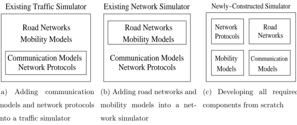
As stated in Chapter 1, a simulator suitable for conducting wireless vehicular com-munication networks research should have the capabilities supported by both a traffic simulator and a network simulator. An intuitive method to construct such a sim-ulator is to write a middleware to combine an existing network simsim-ulator with an existing traffic simulator to provide the required capabilities. Such a method is called the “federated approach” in this dissertation. This approach has the advantage that one need not spend time and effort on developing both a new network simulator and a new traffic simulator. However, because the chosen two simulators may have dif-ferent design architectures, in such a case it is usually difficult or even impossible to combine them with an efficient interaction between them. Another method, called the “integrated approach,” tries to add network simulation functions into an exist-ing traffic simulator, or add microscopic vehicle movement simulation functions into an existing network simulator, or develop a new simulator from scratch with all of these capabilities. Using this approach, except the last choice, one need not develop both a network simulator and a traffic simulator from scratch. It saves time and effort by taking advantage of the existing products. In addition, the program code of the traffic and network simulation subsystems are tightly integrated as a single program. The interaction between them is usually more efficient.
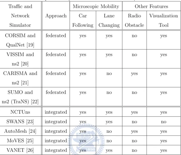
Table 2.1: Microscopic mobility and other features of traffic/network simulators Traffic and Microscopic Mobility Other Features
Network Approach Car Lane Radio Visualization Simulator Following Changing Obstacle Tool CORSIM and federated yes yes no yes
QualNet [19]
VISSIM and federated yes yes no yes ns2 [20]
CARISMA and federated yes no yes yes ns2 [21]
SUMO and federated yes no no yes ns2 (TraNS) [22]
NCTUns integrated yes yes yes yes SWANS [23] integrated yes yes no no AutoMesh [24] integrated yes no yes yes MoVES [25] integrated yes no no yes VANET [26] integrated yes yes no yes
[11], [12], and [13]) and traffic simulators (e.g., [14], [15], [16], [17], and [18]) are available alternatives from which one can choose to combine. Some of them are commercial products while some of them are free and/or open source software. In Table 2.1, we list four existing federated traffic/network simulator combinations: CORSIM/QualNet [19], VISSIM/ns2 [20], CARISMA/ns2 [21], and SUMO/ns2 (TraNS) [22]. Among the listed network and traffic simulators, only SUMO and ns2 are free open source software. This means that only the SUMO/ns2 (TraNS) combination is totally open source and allows researchers to freely modify for their research.
The conceptual architecture of a federated traffic/network simulator is shown in Figure 2.1. This approach uses a middleware to interconnect a traffic simulator and
Road Networks Communication Models Network Protocols Network Simulator Mobility Models Middleware Traffic Simulator
Figure 2.1: The conceptual architecture of a federated traffic/network simulator a network simulator. The middleware provides bidirectional links, usually realized by TCP connections, between the two simulators. Because the traffic simulator is responsible for simulating the road network and vehicle mobility, the latest position of every vehicle is sent from the traffic simulator to the network simulator during simulation. The position update is performed periodically or by the request from the network simulator. In the network simulator, the vehicular position changing affects the calculation of wireless communication models. Based on the calculated result, the network simulator determines whether a network message sent from a vehicle will be successfully received at another vehicle or not. Then, the message transmission/reception result affects the operations of network protocols. This is basically what a network simulator does. In the network simulator, if a vehicle receives a message and this message makes it decide to change its driving behavior (e.g., to change the current route to avoid congested or dangerous area or to stop immediately to avoid a forthcoming collision, etc.), the network simulator sends a request to the traffic simulator asking for such a change. Usually, a vehicular agent is run within the network simulator to receive the message, analyze the information contained in the message, and issue such a request on behalf of the virtual driver driving in a particular vehicle.
The architectural advantage of the federated approach is that in theory it can combine any traffic simulator with any network simulator. However, in practice it is difficult to do so (if not totally impossible). Two independent simulators may have different designs, implementations, and definitions. For example, the used coordinate systems and the representations of continuous vehicular movement may
be different. A transformation mechanism for accommodating these differences must exist in the middleware at the cost of performance degradation during simulation. Besides, a commercial software normally does not release its source code but only exports some pre-defined application program interfaces (API) for external software programs to use. Since the development of new ITS applications advances so quickly, the pre-defined API’s may not meet the demands of new ITS applications.
Regarding the integrated approach, Table 2.1 lists five integrated traffic/network simulators: NCTUns, SWANS [23], AutoMesh [24], MoVES [25], and VANET [26]. This approach works only when the used simulator is open source. Three different methods are possible for constructing a simulator using the integrated approach and they are shown in Figure 2.2. In Figure 2.2a, communication models and network protocols are added into an existing traffic simulator. Because a plenty of commu-nication models and network protocols exist in the real life and they can be very complicated (e.g., IEEE 802.11p [1], IEEE 802.16e [6], etc.), this method usually takes a huge amount of time and effort. Therefore, our survey found no integrated simulator adopting this method. In contrast, in Figure 2.2b, an existing network simulator is extended to include the simulations of road networks and vehicle mo-bility models. This method is more feasible and incurs less cost because a network simulator already has the capability to simulate the mobile node movement (e.g., the commonly used random waypoint mobility model). Based on this capability, it just needs to support road network simulation and apply vehicle mobility models on the mobile node movement. Relatively, this task is easier to accomplish than simulat-ing various complicated communication models and network protocols. Therefore, NCTUns, SWANS, and AutoMesh adopt this method to take advantage of their existing network simulation capabilities. Yet another method is to develop all re-quired components from scratch to construct a new simulator, which is depicted in Figure 2.2c. MoVES and VANET adopt this method. Conceivably, this method will require a very huge amount of time and effort to develop a complete simulator from scratch. It is also the most time-consuming approach to developing an integrated traffic/network simulator.
Network Protocols Mobility Models
Road Networks
Communication Models Existing Traffic Simulator
(a) Adding communication models and network protocols into a traffic simulator
Mobility Models Road Networks Existing Network Simulator
Communication Models Network Protocols
(b) Adding road networks and mobility models into a net-work simulator Mobility Network Protocols Models Models Communication Road Networks Newly−Constructed Simulator
(c) Developing all required components from scratch
Figure 2.2: Three different approaches to constructing an integrated traffic/network simulator
Table 2.1 also compares the microscopic mobility and other important features of each simulator. These features include car following, lane changing, radio obstacles, and the visualization tool. The car-following capability is supported by all simulators listed in Table 2.1. To support this, a road network topology is necessary for vehicles to move on it. Besides, a vehicle’s moving speed is restricted by the vehicle (if any) moving in front of it. With this capability, the simulated vehicular moving paths are more realistic than those generated by the random waypoint mobility model. Regarding the convincingness of simulation results, the random waypoint mobility model commonly used before is unsuitable when running an ITS-related simulation [27]. Thus, the car-following capability is very fundamental for a network/traffic simulator.
To have the lane-changing capability, a platform must support multi-lane roads and lane-changing driving logic in the vehicle mobility model. Table 2.1 shows that some platforms do not have this capability. Lacking this capability will reduce the applications of vehicle mobility simulation. For example, without this capability, if a vehicle breaks down on a multi-lane road, the vehicles behind it can only stop because no lane-changing move can be taken. However, in the real life, they can change lanes to move around this broken vehicle. In addition, lacking the lane-changing capability means that no overtaking will occur during simulation. Therefore, the topology of
the vehicular ad hoc network (VANET) formed on the roads will not change much during simulation. Since this does not reflect the situations in the real life, the simulation results of network protocol studies on such a simplified and unrealistic VANET may be misleading.
As for radio obstacles, they are capable of totally blocking the transmission of wireless signal or reducing the power of wireless signal. In the real world, vehi-cles are usually moving on roads surrounded by buildings. The buildings are radio obstacles that influence the wireless signal transmission. When one wants to con-struct a vehicular network on a simulation platform where more realistic wireless signal transmission among vehicles can be supported, the radio obstacles are needed. Thus, for a network simulator, supporting radio obstacles is an important capabil-ity. Table 2.1 shows that only NCTUns, CARISMA/ns2, and AutoMesh have this capability.
The last capability compared is the support of a visualization tool. It is a graphical user interface (GUI) program displaying the road networks and vehicular movement during simulation or after a simulation is finished. This tool provides visual observations of a simulated network. Moreover, some visualization tools also provide the capabilities of interacting with the simulated network during simulation, such as dynamically changing some system parameters of the simulated network or dynamically controlling vehicular mobility. A visualization tool is very useful in specifying, controlling, and observing the simulated network. Table 2.1 shows that every platform has a visualization tool except SWANS.
Chapter 3
Architecture of NCTUns
As stated in Chapter 1, NCTUns was originally developed as a network simulator and then extended with traffic simulation capabilities. In this chapter, we present the original architecture of NCTUns, including its features, components, design and implementation issues. The extended architecture of NCTUns to support the traffic simulation is left to Chapter 4.
3.1
Introduction to NCTUns
Network simulators implemented in software are useful tools for researchers to de-velop, test, and diagnose network protocols. Simulation is economical because it can carry out experiments without the actual hardware. Also, simulation is flexible because it can study the performances of a system under various conditions. More-over, simulation results are easier to analyze than experimental results because they are repeatable.
Developing a useful network simulator requires much time and efforts. A net-work simulator needs to simulate the hardware characteristics of netnet-working devices (e.g., hub or switch), the protocol stacks employed in these devices (e.g., the learn-ing bridge protocol used in a switch), and the network traffic flows (e.g., TCP/IP or UDP/IP connections). It also needs to provide utilities for configuring network topologies, specifying network parameters, monitoring traffic flows, gathering
statis-tics about a simulated network, and so forth.
To save developing time and efforts, some traditional network simulators only simulate real-life network protocols with limited details. For example, OPNET [12] uses a simplified finite state machine model to model complex TCP protocol process-ing. As another example, ns2 [10] simulates no dynamic receiver advertised window on TCP connections. The simplified simulation design may lead to inaccurate sim-ulation results. In addition, these traditional simulators usually do not support the standard API’s that are supported by operating systems (e.g., the UNIX POSIX socket API). Thus, existing and developing real-life application programs cannot run directly on these simulators. Instead, they must be rewritten to use the internal API provided by these simulators (if any). It is inconvenient for users to use these simulators.
To avoid the inaccurate results and inconvenient application-developing environ-ments, the authors in [28, 29] proposed a kernel re-entering simulation methodology and used it to develop Harvard network simulator [30]. Based on the simulation methodology, the NCTUns network simulator [7, 8, 9] was developed as the succes-sor of Harvard network simulator. Using the kernel re-entering simulation method-ology, NCTUns directly uses the real-life TCP/IP and UDP/IP protocol stacks to generate more realistic simulation results. Besides, real-life application programs can run directly on NCTUns because NCTUns supports the standard API provided by the Linux Fedora operating systems. Moreover, NCTUns improves the simula-tion capabilities that Harvard network simulator does not support, such as various media access control protocols and wireless communication/channel models.
3.1.1
Major Components
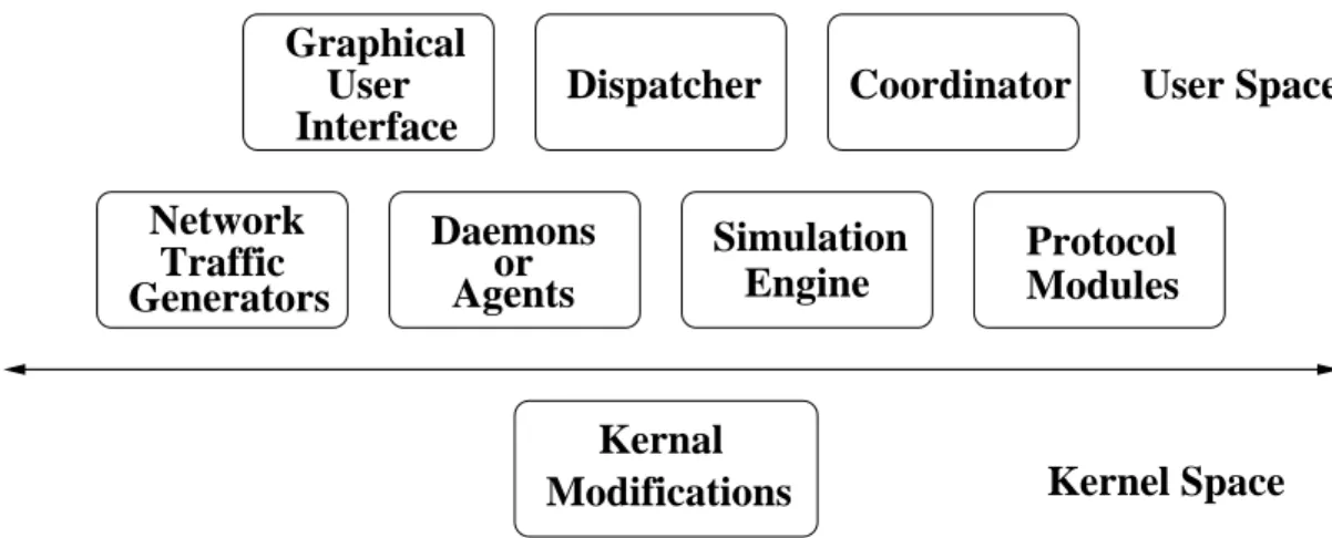
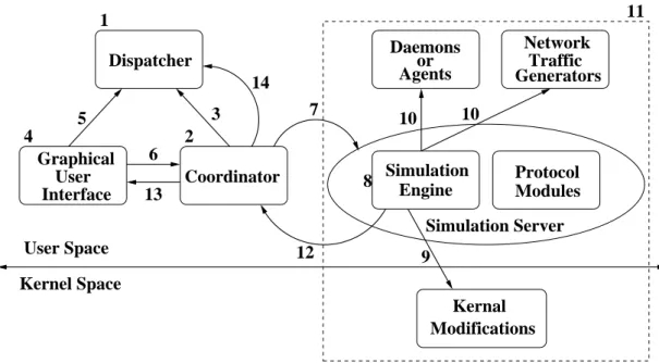
NCTUns uses a distributed architecture to support the remote simulation and the construction of a simulation service center. Functionally, it can be divided into eight separate components. In Figure 3.1, each component is depicted and classified according to where it is run in the operating system – the user space or the kernel
GeneratorsTraffic Network Simulation Engine Protocol Modules Graphical User Interface Dispatcher Daemons or Agents User Space Modifications Coordinator Kernel Space Kernal
Figure 3.1: The eight components of NCTUns space. Each component’s functionalities are described below.
• Graphical User Interface (GUI)
The GUI is a user-space program. It provides the utilities to edit a network topology, configure the protocol modules used inside a network node, specify mobile nodes’ moving paths, plot performance curves, display packet transfer animations, etc. Instead of doing lots of editing work on lots of configuration files, users can easily complete the setting of a simulated network by the user-friendly utilities. Based on the setting, the GUI automatically generates the required configuration files. This not only saves lots of time but also avoids typos that usually occur when a user has to edit all of the configuration files. During simulation, users can change/query some system parameters through the GUI, such as some network interface’s maximum/current output queue length. When a simulation is finished, the simulation results can be displayed by some utilities provided by the GUI. For example, the GUI can record each packet’s transmission/reception into a binary-format log file during simulation. When the simulation is done, the GUI can display the animation of packet transmission/reception according to the log file, or it can translate the binary-format file into an ascii-binary-format file so that a user can check the log using a text
editor. Another example is that the changing of a network interface’s output queue length over time can be drawn on a two-dimension graph. Besides, the graph can be captured into a file for further use.
• Simulation Engine
The simulation engine is a user-space program. It functions like a small op-erating system. Through a set of defined API’s, it provides useful and basic simulation services to protocol modules. Such services include virtual clock maintenance, timer management, event scheduling, etc. The simulation engine needs to be compiled with various protocol modules to form the “simulation server.” When executed to service a job, the simulation server takes a config-uration file suite as its input, runs the simulation, and generates log files and statistics as its output. Because the simulation server uses the kernel’s tunnel interfaces that can not be shared with other processes during simulation, no more than one simulation server can run concurrently on a single machine. • Protocol Modules
A protocol module is like a layer of a protocol stack. It performs a specific protocol or function. For example, the address resolution protocol (ARP) or a first-in-first-out (FIFO) queuing mechanism is implemented as a protocol mod-ule. A protocol module is not an independent user-space program. Instead, It needs to be compiled with the simulation engine to form the simulation server. Usually, inside the simulation server, multiple protocol modules are linked into a chain to function as a protocol stack.
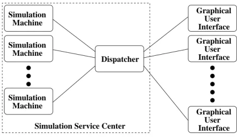
• Dispatcher
The dispatcher is a user-space program responsible for simulation job manage-ment. It should be executed and remain alive all the time to manage multiple simulation machines on each of which a simulation server is run. The dis-patcher is the key role to support the NCTUns distributed architecture. Like that shown in Figure 3.2, the dispatcher can operate between a large number
Dispatcher Graphical User Interface Graphical User Interface Graphical User Interface Simulation Machine Simulation Machine Simulation Machine
Simulation Service Center
Figure 3.2: The distributed architecture of NCTUns
of GUI users and a large number of simulation machines. It behaves like the manager of a simulation service center. When a GUI user submits a simula-tion job to the dispatcher, the dispatcher will select an available simulasimula-tion machine to service this job. If all simulation machines are busy on servicing at this time, the submitted job can be queued in the dispatcher waiting for a simulation machine to become available. Of course, in the case that only one GUI user exists and one simulation server is required, all the NCTUns components can run on a single machine.
• Coordinator
The coordinator is a user-space program. It operates like the agent of the simulation server and deals with the coordination among the GUI program, the dispatcher, and the simulation server. On every simulation machine, a coordinator program needs to be executed and remain alive. Its main task is to let the dispatcher know whether the simulation machine is currently busy running a simulation or not. When executed, it immediately registers itself with the dispatcher to join the dispatcher’s simulation service center. Later on, when its status (idle or busy) changes, it will notify the dispatcher of its new status. This enables the dispatcher to always choose an available simulation
machine from its simulation service center to service a job. When the coor-dinator receives a job, it forks (executes) a simulation server to simulate the specified network and protocols. When the simulation server is running, the coordinator communicates with the dispatcher and the GUI program on behalf of the simulation server. For example, periodically the simulation server sends the current virtual time of the simulated network to the coordinator. The coordinator then forwards this information to the GUI program. This enables the GUI user to know the progress of the simulation.
• Daemons or Agents
A daemon or an agent runs at the user space to provide some specific service. For example, the routing information protocol (RIP) routing daemons, as well as the open shortest path first interior gateway protocol (OSPF) routing dae-mons, exchange routing messages and set up system routing table during sim-ulation. Besides, the home agents and foreign agents are executed to provide the mobile IP service.
• Traffic Generators
A traffic generator runs at the user space to generate TCP or UDP network packets into the simulated network. Unlike a daemon or an agent, a traffic generator does not provide a specific service but just generates background network traffic. For one pair of traffic generators provided by NCTUns, named stg and rtg, they can be configured to produce network packets based on a specified packet transmission pattern. Moreover, they can generate packets following a real-life packet log to produce more realistic background traffic. • Kernel Modifications
The last component is the modifications that need to be made to the kernel so that a simulation server can correctly run on it. For example, during a simulation, the timers of TCP connections used in the simulated network need
Dispatcher GeneratorsTraffic Network Graphical User Interface Coordinator Simulation Engine Protocol Modules Daemons or Agents Simulation Server 5 2 1 4 6 User Space Kernel Space 7 3 Modifications Kernal 8 9 10 10 11 12 13 14
Figure 3.3: The execution procedure of NCTUns
to be triggered by the virtual time rather than by the real time. The kernel modifications will be elaborated later in this chapter.
3.1.2
Execution Procedure
The above-mentioned eight major components comprise the main NCTUns frame-work. They work together to complete network simulations. Here, we present the execution procedure among all of them to explain how they work with each other during simulation. Figure 3.3 shows the procedure step by step and each step is stated below.
1. First of all, a dispatcher should be ready (executed) for accepting the regis-tration from a coordinator or the simulation job request from a GUI.
2. A coordinator is executed as the agent of the simulation server. Note that so far the simulation server has not been forked by the coordinator.
3. The coordinator builds a TCP connection to the dispatcher and registers its existence through the connection. Now, the dispatcher has the information
about the registered coordinator and treats it as an available agent that can provide the simulation server for service.
4. A user executes the GUI program to draw a network topology, configure net-work parameters, and let the GUI generate all the required configuration files. Finally, the user triggers a sending out of a simulation jog request.
5. The GUI asks the dispatcher for an available coordinator and waits for the response from it. If a coordinator is available at this time, the response is returned immediately and the status of that coordinator is set to busy by the dispatcher. Otherwise, the GUI has to wait until any busy coordinator becomes available again. If no coordinator has registered to the dispatcher, the response indicating this situation is returned immediately.
6. After obtaining the information of an available coordinator (e.g., the IP ad-dress and listen port number used by the coordinator’s TCP passive socket), the GUI builds a TCP connection to that coordinator and sends all the con-figuration files to it to start the simulation.
7. The coordinator places the configuration files into a dynamically allocated directory and forks the simulation server, which includes the simulation engine and some required protocol modules.
8. The simulation engine reads in those configuration files to allocate and ini-tialize the required object for each protocol module, to construct the protocol module stack for each network node, to generate events that will be triggered during simulation to execute daemons, agents, or traffic generators, to set up the required system routing entries, to set up the required tunnel interfaces, and to complete other initialization procedures.
9. The simulation engine resets the states of the NCTUns kernel data structures. For example, the simulated virtual time is reset to zero.
10. If any daemon, agent, or traffic generator has to be run at the beginning of a simulation, it is forked (executed) by the simulation engine now. Of course, a daemon, an agent, or a traffic generator can also be executed at any time during simulation.
11. When the simulation starts, daemons (if any), agents (if any), traffic generators (if any), the simulation engine, the protocol modules, and the NCTUns kernel parts work together to conduct the network simulation. The daemons or agents provide network services. The traffic generators generate background traffics. The kernel provides the operations of the real-life TCP/IP and UDP/IP pro-tocols. The simulation engine and protocol modules provide the operations of various data link layer and physical layer protocols.
12. When the simulation is finished, the simulation engine informs the coordinator, kills all of the daemons (if any), agents (if any), or traffic generators (if any), and finally terminates itself.
13. The coordinator sends back all the log files and statistics files collected during simulation to the GUI.
14. Finally, the coordinator informs the dispatcher that it is available again. The dispatcher then set the coordinator’s status to idle.
The current version of NCTUns can only run on the operating systems of Linux Fedora series. Because the kernel modification is required to let NCTUns’ architec-ture work, the kernel source codes must be accessible, modifiable, and able to be re-compiled. Thus, the qualified Linux Fedora series are chosen.
3.2
Kernel Re-entering Simulation Methodology
The kernel re-entering simulation methodology is the key design that allows NC-TUns using the real-life TCP/IP and UDP/IP protocol stacks and allows real-life application programs running on NCTUns. In this methodology, the tunnel interface
is the key facility. Before explaining how this methodology is applied on NCTUns, we first introduce how a packet is transmitted over a one-hop network connection between two machines in the real world. Based on it, we then show how the tunnel interface is used to realize the simulation of the same one-hop network connection on a single machine.
3.2.1
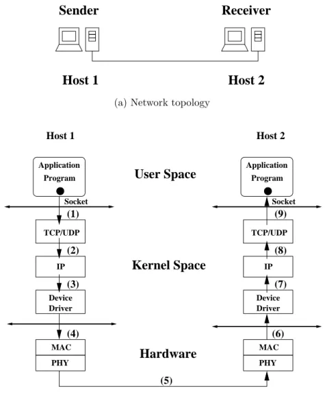
A Real-world Host-to-host Connection
In Figure 3.4a, two real host computers are connected by a network line that could be any kind. A Linux Fedora operating system are run on each of them to provide networking services through the standard POSIX socket interface. We assume that Host 1 is the sender of a network packet and Host 2 is the receiver of that packet. Between being sent and being received, the packet goes through several steps that are depicted in Figure 3.4b and described as follows.
1. The application program run on Host 1 sends out a data segment through the socket. First, the data segment is copied from the user space to the kernel space. Then it reaches the TCP/UDP layer (which is defined as the transportation layer in the OSI reference model [31]).
2. The data segment is encapsulated with a TCP/UDP header and becomes a TCP/UDP packet. It then is passed to the IP layer (which is defined as the network layer in the OSI reference model).
3. The TCP/UDP packet will be encapsulated again with an IP header. In addition, a MAC header could be added into this IP packet. The format of the MAC header depends on which kind of media access control protocol is used at the next step. Then this packet is put into a network device driver’s output queue to wait for being fetched by the driver’s associated network interface card, which is a hardware device.
4. The network interface card copies the queued IP packet from the kernel space to its memory space. Then it sends the packet out on the medium, which is
Host 1
Host 2
Sender
Receiver
(a) Network topology
TCP/UDP IP Device Driver TCP/UDP IP Device Driver PHY MAC PHY MAC Host 2 Host 1
User Space
Kernel Space
Hardware
(1) (2) (3) (4) (6) (7) (8) (9) Socket Socket Application Application Program Program (5)(b) Network packet transmission path
Figure 3.4: A host-to-host network in the real world
a network line in this case. The sending operation is controlled by the media access control (usually called MAC layer and defined as the data link layer in the OSI reference model) module, that is usually made as a firmware within a network interface card.
5. After going through the processes of encoding and modulation in the PHY layer (which is defined as the physical layer in the OSI reference model), the packet stored in digital data format is transformed into a series of analog sig-nals. Finally, the signals are emitted by the radio frequency module within the
network interface card. When the signals reach the receiving radio frequency module, the process of transforming analog signals into digital data format is conducted to obtain the original IP packet.
6. The interface card copies the packet from its memory space to its associated network device driver’s input queue and informs the kernel about this incoming packet by triggering a software interrupt.
7. The kernel fetches the packet and puts it to the IP layer. The MAC header and IP header are stripped off here and the resulting TCP/UDP packet is then sent up to the TCP/UDP layer.
8. After stripping the TCP/UDP header, the kernel puts the data segment in the corresponding socket’s receive buffer and informs the receiving application program to fetch the data segment.
3.2.2
A Simulated Host-to-host Connection
In Figure 3.4, one sees that the real-life TCP/IP or UDP/IP protocol stack is jointed with the real hardware network interface card by the network device driver. Usually, a single machine can support only a few number of network interface cards. This could fail a network simulator to simulate hundreds or thousands of hosts on a single machine and to use the real-life TCP/IP or UDP/IP protocol. NCTUns uses the tunnel interface to solve this problem.
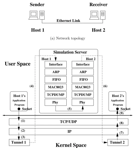
The tunnel interface is the key facility in the kernel re-entering methodology. A tunnel interface is a pseudo network interface and supported by most Linux operat-ing systems. It operates like a network device driver but no real hardware network interface card attaches to it. Figure 3.5 shows how NCTUns simulates the net-work packet transmission in the netnet-work depicted in Figure 3.4a by using tunnel interfaces.
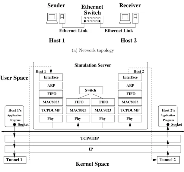
The network topology depicted in Figure 3.5a is the same as that depicted in Figure 3.4a, except that we assume that the network connection is an Ethernet link.
Host 1
Host 2
Sender
Receiver
Ethernet Link
(a) Network topology
Interface ARP FIFO MAC8023 TCPDUMP Phy Interface ARP FIFO MAC8023 TCPDUMP Phy Tunnel 1 Tunnel 2 Host 1 Host 2
User Space
Simulation Server TCP/UDP IPKernel Space
(1) (3) (2) Socket Host 1’s Application Program (4) (5) (6) (9) (8) (7) Socket Host 2’s Application Program(b) Network packet transmission path
Figure 3.5: An Ethernet host-to-host network in simulation
Note that, in Figure 3.5b, the simulation server, the Host 1’s application program, and the Host 2’s application program are all running on a single machine where the simulation is conducted. The application program can be a daemon, an agent, or a traffic generator. The network packet transmission steps are depicted in Figure 3.5b and described as follows.
1. The application program recognized as a Host 1’s application programs sends out a data segment through the socket. The data segment is copied from the user space to the kernel space. Then it reaches the TCP/UDP layer.
2. The data segment is encapsulated with a TCP/UDP header and becomes a TCP/UDP packet. It then is passed to the IP layer.
3. The TCP/UDP packet will be encapsulated again with an IP header. Because the exit interface is a tunnel interface, no MAC header is added into the IP packet by the kernel. Then, instead of being put into a network device driver’s output queue, the packet is put into the output queue of Tunnel 1, which is a tunnel interface. The simulation server sets this tunnel interface to be associated with Host 1 before the simulation starts. In order to let a tunnel interface imitate a real Ethernet interface, we modify the tunnel interface to add an Ethernet header into the IP packet before the packet is put into the queue. The field of destination MAC address in the header is set to the next hop’s IP address instead of the next hop’s MAC address. This is because the next hop’s MAC address is unavailable here.
4. Later on, the simulation server reads the queued IP packet from Tunnel 1 to the Interface module that is associated with Tunnel 1. Within the simulation server, the ARP module performs the ARP protocol to find out the next hop’s MAC address according to the next hop’s IP address. It then fills all the fields of the Ethernet header. The FIFO module functions as an interface output queue. In this module, the queue length is synchronized with the associated tunnel interface’s queue length so that in effect only one output queue exists for an interface. The MAC8023 module performs the IEEE 802.3 MAC pro-tocol (usually known as CSMA/CD). The TCPDUMP module supports the tcpdump program provided by Linux operating systems.Finally, the Phy mod-ule simulates the transmission delay and the propagation delay of the packet and sends the packet to the receiving Phy module.
5. The sending Phy module and receiving Phy module are bound together by a wired link. The sent packet from the sending module will reach the receiving module after the time period of propagation delay that is specified by users. The received packet travels up the protocol modules to the Interface module
associated with Tunnel 2, which is the tunnel interface associated with Host 2.
6. The Interface module writes the packet to Tunnel 2’s input queue and informs the kernel about this incoming packet by triggering a software interrupt. Note that the Ethernet header is not copied back to the kernel space.
7. The kernel fetches the packet and puts it to the IP layer. The IP header is stripped off here and the resulting TCP/UDP packet is then sent up to the TCP/UDP layer.
8. After stripping the TCP/UDP header, the kernel puts the data segment in the corresponding socket’s receive buffer and informs the application program recognized as a Host 2’ application programs to fetch the data segment. During the simulation described above, the transmitted packet enters and exits the same kernel twice on a single machine. This is why this methodology is named “kernel re-entering simulation methodology.” As stated before, using this methodol-ogy, NCTUns uses the real-life TCP/IP and UDP/IP protocol stacks and supports real-life application programs to run on itself.
3.2.3
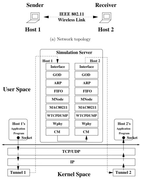
A Simulated Mobile-host-to-mobile-host Connection
Next, we show a simulated network containing two mobile hosts each of which is equipped with an IEEE 802.11b wireless interface. The network topology is shown in Figure 3.6a and the packet transmission path is depicted in Figure 3.6b. Comparing Figure 3.6b with Figure 3.5b, one can see that the only difference is the protocol module stack within the simulation server.
Regarding the protocol stack of a mobile host, the GOD module is the default routing daemon module for an IEEE 802.11b wireless interface. This module does not perform any routing protocol during simulation. Instead, it sets the routing en-tries according to a schedule that is provided by the GUI. When a user manipulates the GUI to set each mobile node’s moving path before starting the simulation, the
Host 2
IEEE 802.11 Wireless Link
Host 1
Sender
Receiver
(a) Network topology
Tunnel 2 Socket Host 2’s Application Program MNode FIFO ARP GOD Interface ARP FIFO MNode GOD Interface
User Space
TCP/UDP IP Tunnel 1 Socket Host 1’s Application Program Simulation Server MAC80211 WTCPDUMP Host 1 MAC80211 WTCPDUMP Host 2Kernel Space
Wphy CM Wphy CM(b) Network packet transmission path
Figure 3.6: An IEEE 802.11 mobile-host-to-mobile-host network in simulation GUI calculates each mobile node’s routing entries according to the relative move-ments among mobile nodes. The resulting routing entries are written into a file by the GUI. Later on, when the simulation starts, the simulation server reads in these routing entries and schedules events to be triggered during simulation. When one of these events is triggered, the corresponding GOD module’s routing table is updated. The GOD module represents an optimum routing path search result and is usually used to compare with other routing protocol implementations. In addi-tion to the GOD module, NCTUns also provides AODV, ADV, DSDV, and DSR
modules. Note that all of these routing protocols are implemented in the form of protocol module. Of course, they can be implemented as a user space daemon, like the RIP and OSPF daemons mentioned before.
Besides, the MNode and MAC80211 modules perform the IEEE 802.11b MAC protocols (usually known as CSMA/CA). The WTCPDUMP module (W stands for wireless) supports the tcpdump program provided by Linux operating systems. Regarding the Wphy module, it is like the Phy module but it does not have the one-to-one connection relationship with another Wphy module. Because the wire-less signals are media with broadcast nature, the Wphy module has the one-to-many connection relationship with other Wphy modules, and so do other counterpart mod-ules used in different types of wireless networks. After the Wphy module determines those other Wphy modules to which a duplicated packet should be sent, an outgo-ing packet is duplicated based on the number of target Wphy modules. Next, each duplicate is sent to the CM module. In the CM module, several channel models can be selected, each of which is associated with different wireless signal transmission technologies and environments. The degradation of wireless signal power is calcu-lated in the CM module based on the recalcu-lated physical layer parameters, such as the antenna gain patterns used in the sender mobile host and the receiver mobile host.
3.2.4
A Simulated Host-to-switch-to-host Connection
Next, we insert a layer-2 Ethernet switch into the connection between two hosts, as that shown in Figure 3.7a. Comparing Figure 3.7b with Figure 3.5b, one can see that the difference is the switch’s protocol module stacks within the simulation server. In this example network, only two ports of the switch are used. Thus, only two protocol module stacks, each of which is for one port, are created by the simulation server. Because the switch is a layer-2 device, the Phy module (layer 1) and the MAC8023 module (layer 2) are put into the protocol stack. The Switch module determines which port an incoming packet should be sent to according to the destination MAC address recorded in that packet’s Ethernet header. Besides,
Sender
Ethernet
Receiver
Switch
Ethernet Link Ethernet Link
Host 1
Host 2
(a) Network topology
Interface ARP FIFO MAC8023 TCPDUMP Phy FIFO MAC8023 Phy FIFO MAC8023 Phy Switch Interface ARP FIFO MAC8023 TCPDUMP Phy Host 2 Host 1 Simulation Server Tunnel 2 TCP/UDP IP
Kernel Space
User Space
Socket Tunnel 1 Host 1’s Application Program Socket Host 2’s Application Program(b) Network packet transmission path
Figure 3.7: An Ethernet host-to-switch-to-host network in simulation
instead of implementing additional output queue functions in the Switch module, we use the existing FIFO module. Thus, the FIFO module functions as each switch port’s output queue here.
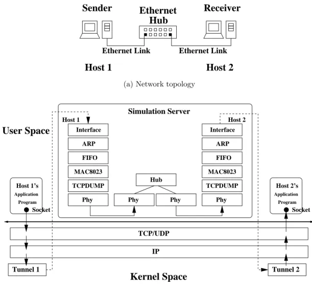
3.2.5
A Simulated Host-to-hub-to-host Connection
Next, we replace the layer-2 Ethernet switch with a layer-1 Ethernet hub on the connection between two hosts. The network topology is shown in Figure 3.8a. Com-paring Figure 3.8b with Figure 3.7b, one can see that the difference is that each of the hub’s ports does not have the MAC8023 module (layer 2). This difference
deter-mines the different simulation method on packet forwarding. Because an Ethernet switch is a layer-2 device, it simulates a store-and-forward way between a packet entering it from one port and leaving it from another port. A packet experiences the transmission delay when it travels through the switch. However, because an Ethernet hub is a layer-1 device, it simulates a pass-through way. That means a packet experiences no delay between entering a Ethernet hub and leaving it.
During simulation, the log of the packet transmission/reception from one device to another device is usually achieved by the layer-2 MAC modules located in the sending device and receiving device respectively. In the case of a switch device, its MAC modules deal with the log. However, in the case of a hub device, the Hub module has to do the log. For example, when a packet enters the hub, the Hub module has to trace the packet’s source MAC module and destination MAC module. Besides, it has to keep monitoring the packet’s reception status (success or failure) in the destination MAC module. When the packet’s reception status is known, the Hub module has to do two logs. For the real source MAC module, the Hub module functions as its corresponding destination MAC module to complete the first log. For the real destination MAC module, the Hub module functions as its corresponding source MAC module to complete the second log. Lacking of the Hub module’s log capability does not affect the simulation correctness but just loses some simulation detail for debugging (if needed) and for displaying the animation of packet transmission/reception.
3.2.6
A Simulated Host-to-router-to-host Connection
In this case, we add a layer-3 Ethernet router into the connection between two hosts, as that shown in Figure 3.9a. Because the Ethernet router is a layer-3 device, it performs the routing functions that is provided in the kernel space. In Figure 3.9b, one can see that the router device has two protocol stacks each of which is exactly the same as a host’s protocol stack. Besides, the Interface module belonging to the router’s first interface is associated with Tunnel 3 in the kernel space, while the
Sender
Ethernet
Receiver
Ethernet Link Ethernet Link
Host 1
Host 2
Hub
(a) Network topology
Tunnel 2 Interface ARP FIFO MAC8023 TCPDUMP Phy Interface ARP FIFO MAC8023 TCPDUMP Phy Host 2 Phy Phy Hub Host 1 Simulation Server TCP/UDP IP
Kernel Space
User Space
Socket Tunnel 1 Host 1’s Application Program Socket Host 2’s Application Program(b) Network packet transmission path
Figure 3.8: An Ethernet host-to-hub-to-host network in simulation
Interface module belonging to the router’s second interface is associated with Tunnel 4 in the kernel space.
Regarding the simulation of packet transmission in this network, a packet has to travel a host-to-router connection first, that is equivalent to a host-to-host con-nection except that the router is not the destination of the packet. When it reaches the Interface module of the router’s first interface, it is written to Tunnel 3 in the kernel space. Then, because the packet’s destination IP address indicates that it has not yet reached the destination interface, it is forwarded to the Tunnel 4 by the kernel’s forwarding function. Later on, the simulation server reads the packet from
Sender
Ethernet
Receiver
Router
Ethernet Link Ethernet Link
Host 1
Host 2
(a) Network topology
Interface ARP FIFO MAC8023 TCPDUMP Phy Interface ARP FIFO MAC8023 TCPDUMP Phy Interface ARP FIFO MAC8023 TCPDUMP Phy Interface ARP FIFO MAC8023 TCPDUMP Phy Host 2 User Space Socket Tunnel 1 Host 1’s Application Program Socket Host 2’s Application Program TCP/UDP IP
Tunnel 3 Tunnel 4 Tunnel 2
Host 1 Interface 1 Interface 2 Router Router
Simulation Server
Kernel Space
(b) Network packet transmission path
Figure 3.9: An Ethernet host-to-router-to-host network in simulation
Tunnel 4 to the Interface module of the router’s second interface. Then the packet continues traveling a router-to-host connection and reaches its destination host.
3.3
Routing Scheme
In the architecture of NCTUns, the real-life IP protocol stack in the kernel space is involved. The routing/forwarding functions in the kernel is directly used without modification. In other words, the real-life routing scheme has to be followed so that the kernel’s routing/forwarding functions can work correctly to forward IP packets.
However, a routing entry conflict problem occurs when setting the routing entries for a simulated network using the original routing scheme. Next, we explain the problem and the solution to it.
Figure 3.10a shows the example network topology. Two class C subnets are jointed by a Ethernet router. One’s subnet ID is 1.0.1.0/24 (referred as subnet 1 later) and the other’s is 1.0.2.0/24 (referred as subnet 2 later). Host 1 is placed under subnet 1 and its associated tunnel interface is tun1. The IP address assigned to tun1 is 1.0.1.1. Host 2 is placed under subnet 2 and its associated tunnel interface is tun2. The IP address assigned to tun2 is 1.0.2.1. Regarding the router, it has two interfaces in this example network. One is attached to subnet 1 and its associated tunnel interface is tun3. The IP address assigned to tun3 is 1.0.1.2. The other interface is attached to subnet 2 and its associated tunnel interface is tun4. The IP address assigned to tun4 is 1.0.2.2.
Based on the original routing scheme, the required routing entries for Host 1, Host 2, and the router are listed in Figure 3.10b. Regarding the entries for Host 1, if the outgoing packet’s destination IP address is 1.0.1.2, it is sent out through tun1 directly because the destination is located at the same subnet as Host 1 is located. If the outgoing packet’s destination IP address is 1.0.2.1 or 1.0.2.2, it is sent to the gateway interface with the IP address 1.0.1.2 because the destination is located at different subnet. The routing entries for Host 2 and the router are set using the same rules to set Host 1’s routing entries.
The individual set of routing entries of each device seems to work well to route packets in this network. However, because NCTUns runs on a single machine with a single kernel, only one kernel routing table exists to store the routing entries. If all of the routing entries listed in Figure 3.10b are added into the only routing table, a conflict situation occurs. That is, for any destination IP address, two routing entries with different gateway IP address and different output interface need to be set. This conflict situation fails the routing function in the simulated network.
When inspecting each pair of conflicted routing entries, one can see that each entry belongs to different network device. In other words, losing the information of
1.0.1.1 1.0.1.2 1.0.2.2 1.0.2.1
Host 1 Router Host 2
tun1 tun3 tun4 tnn2
(a) Network topology
1.0.1.2 0.0.0.0 tun1 1.0.2.1 1.0.1.2 tun1 1.0.2.2 1.0.1.2 tun1 Dst Gw If
For Host 1 For Router For Host 2
1.0.1.1 0.0.0.0 tun3 1.0.2.1 0.0.0.0 tun4 Dst Gw If 1.0.2.2 0.0.0.0 tun2 1.0.1.1 1.0.2.2 tun2 1.0.1.2 1.0.2.2 tun2 Dst Gw If
(b) Routing entries with conflicts
For Host 1 For Router For Host 2
1.2.1.1 0.0.0.0 tun3 2.2.1.1 0.0.0.0 Dst Gw If 2.1.2.2 0.0.0.0 tun2 2.1.1.1 2.1.2.2 tun2 2.1.1.2 2.1.2.2 tun2 Dst Gw If 1.1.1.2 0.0.0.0 tun1 1.1.2.1 1.1.1.2 tun1 1.1.2.2 1.1.1.2 tun1 Dst Gw If 1.2.2.1 2.2.2.1 0.0.0.0 0.0.0.0 tun4 tun3 tun4
(c) Routing entries without any conflict
Figure 3.10: An example of the routing scheme used in NCTUns
the source device that sending packets leads to the conflict. Thus, the NCTUns’ solution is to add the IP address of the tunnel interface from which a packet is sent out into the destination IP address in corresponding routing entries.
Figure 3.10c shows the modified routing entries for each devices in the simulated network. Those underscores indicate the modified portion in destination and gate-way IP addresses. Regarding the entries for Host 1, the first two octets of each IP address is replaced by the last two octets of Host 1’s output tunnel interface’s IP address. That is 1.1. Regarding the entries for Host 2, the same change is applied based on the last two octets of its output tunnel interface’s IP address. That is 2.1. For the router, because it has two tunnel interfaces, each tunnel interface’s IP address is used to change the IP address in each routing entry. Thus, the number