Future Generation Computer Systems 9 (1993) 235-240 235 North-Holland
The M2 hierarchical multiprocessor
Y e n - J e n O y a n g *, D a v i d J i n s u n g S h e u , C h i h - Y u a n C h e n g a n d C h e n g - Z e n Y a n g Department of Computer Science and Information Engineering, National Taiwan University, Taipei, Taiwan
Abstract
This paper discusses the design and development of a bus-based hierarchical multiprocessor named M 2. The primary design goal of the M 2 is to derive a multiprocessor architecture that features much higher degree of scalability than the shared-memory shared-bus architecture to meet the ever increasing processing power demanded by large database/ knowledgebase computing and transaction processing. If compared with other hierarchical multiprocessors, the M E is distinctive in its memory configuration, which is aimed at avoiding severe inter-CPU interference due to page-swapping events. If compared with a group of multiprocessors connected by a local area network, the M 2 enjoys higher scalability due to higher bandwidth of the backplane bus.
Keywords. Hierarchical multiprocessor, scalability; shared-memory shared-bus multiprocessor; message-passing; distributed memory.
1. introduction
In recent years, designers of h i g h - p e r f o r m a n c e workstations and file servers have started turning to multiprocessors for their new generation prod- ucts. In this development, the s h a r e d - m e m o r y shared-bus configuration prevails due to its hard- ware simplicity and cost-effectiveness. However, the s h a r e d - m e m o r y shared-bus configuration also suffers a serious deficiency of very limited scala- bility, generally up to 10 to 20 CPUs, due to limited bandwidth of the shared bus. Since ever- increasing processing power is in d e m a n d for large d a t a b a s e / k n o w l e d g e b a s e computing and transaction processing, design of highly scalable multiprocessors is of great significance and inter- est to c o m p u t e r architects [1]. Motivated by this observation, we started the M 2 hierarchical mul- tiprocessor project in Spring 1991.
In the design of the M 2, several guidelines were cautiously observed. These guidelines are: (1) T h e machine is intended to run data-
b a s e / k n o w l e d g e b a s e and transaction process- ing applications. Hence, the design should be optimized for that kinds of workloads. Typical * Corresponding author.
workloads comprise a large n u m b e r of paral- lel tasks that are either weakly coupled or even completely independent. T h e parallel tasks could come from a n u m b e r of re- questers that take action at the same time or f r o m a complicated job that are d e c o m p o s e d into a n u m b e r of pieces. Each task may fur- ther exhibit some degree of lower level paral- lelism.
(2) T h e architecture design should exploit latest advances in V L S I and packaging technologies so that the machine is superior in respect to cost/effectiveness.
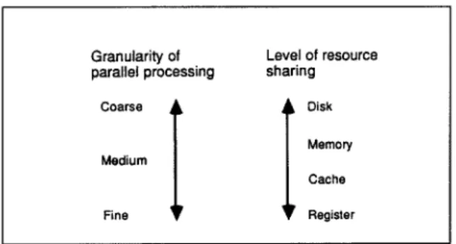
(3) T h e design should accord with the pragmatic c o r r e s p o n d e n c e illustrated in Fig. 1 between the granularity of parallel processing and the level of resource sharing among parallel hard- ware units.
With these three guidelines, the M 2 architecture is designed with two levels of multiprocessing hierarchy. At the first level of the hierarchy, the s h a r e d - m e m o r y shared-bus structure is employed. At the second level of the hierarchy, a physically distributed with no r e m o t e access m e m o r y orga- nization is employed. T h r o u g h the employing of the hierarchical structure and m e m o r y organiza- tions, the M 2 features a much higher degree of 0376-5075/93/$06.00 © 1993 - Elsevier Science Publishers B.V. All rights reserved
236 Y.J. Oyang et al.
Granularity of Level of resource
parallel processing sharing
C°arse
I IDisk
M e m o r yM e d i u m
Cache
Fine Register
Fig. 1. Pragmatic correspondence between the granularity of parallel processing and the level of resource sharing
among parallel hardware units.
scalability than the shared-memory shared-bus architecture and a good p e r f o r m a n c e / c o s t ratio. In the following part of this paper, we will elaborate the architecture and design decisions of the M E in Section 2. Then, in Section 3, we will
describe a prototype M 2 that we have been de- veloping. Finally, we will conclude our discussion in Section 4.
2. The M 2 architecture and design decisions
2.1. Overview o f the M 2 architecture
Figure 2 depicts the block diagram of the M 2 hierarchical multiprocessor. The M 2 architecture consists of two levels of multiprocessing hierar- chy. At the first level of the hierarchy, multiple CPUs, each with a private cache, and a shared cluster memory are placed on a printed-circuit board and connected through an on-board snoop- ing bus to form a CPU cluster. In the M 2, the shared cluster memory in a CPU cluster serves as the main memory to the CPUs in the cluster. Therefore, structure-wise, there is no difference
CPU Cluster 1
/ : ! "
•i I c
~ . : • ..!'d:: !:.!:.::-:.-/ . ... ::~.: Shared Cluster CPU Cluster McPU
L
J
Backplane Message-Passing Bus
Controller
I/0
Controller
The M 2 hierarchical multiprocessor 237 between a M 2 CPU cluster and a conventional
shared-memory shared-bus multiprocessor. T h e second level of the M 2 hierarchy is made up of multiple CPU clusters connected through a backplane message-passing bus. At this level of hierarchy, memory is distributed in both physical and logical senses. That is, the memory of a cluster is accessible only to the cluster itself and is not accessible to other clusters. Communica- tion between clusters is carried out through pass- ing messages.
In the M 2, also connected to the backplane message-passing bus are I / O controllers. The I / O controllers and the CPU clusters operate u n d e r a client-server model [3]. Some I / O con- trollers, e.g. disk controllers, are associated with a large memory which serves as the disk/file cache. In such cases, the memory in the CPU cluster and the memory associated with the I / O con- troller constitute a two-level disk/file cache. Data consistence between the memories in the CPU clusters and I / O controllers is maintained through executing a directory-based coherence protocol [4].
2.2. Architectural features and design considera- tions
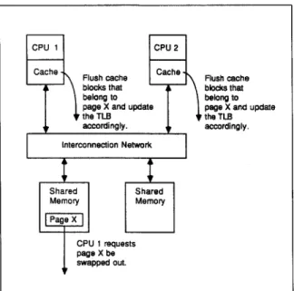
This subsection elaborates the main features and design considerations of the M 2 architec- ture. If compared with other hierarchical multi- processors [5,6], the M 2 is distinctive in its mem- ory organization at the second level of the hierar- chy, In the M 2, a physically distributed with no remote access memory organization is employed. This design is aimed at avoiding severe page- swapping-induced inter-CPU interference. The page-swapping-induced inter-CPU interference, as illustrated in
Fig. 3,
is an inheritance of mem- ory sharing among CPUs. For a group of CPUs that share memory, regardless of if the memory is physically distributed or not, each CPU must be notified with the page-swapping events occurring in the shared memory so that the C P U would flush the blocks that are cached in its private caches from the page being swapped out and update its T L B (Translation Lookaside Buffer) contents accordingly. Since the page-swapping-in- duced inter-CPU interference grows linearly with the n u m b e r of CPUs that share memory, it is inappropriate to employ the shared-memory ap-CPU 1 CPU 2
Cache ~ Flushcache Cache,
• \ blocks that
belong to | page X and update 9 ' the TLB accordingly. Interconnection Network J Sh e ~ M~p~ ory CPU 1 requests page X be swapped out. ~ Flush cache blocks that belong to page X and update
the TLB accordingly.
Fig. 3. Illustration of inter-CPU interference caused by page-swapping events.
proach beyond a certain extent. Therefore, it was determined that a physically distributed with no remote access memory scheme should be em- ployed at the second level of the M 2 hierarchy.
Nevertheless, the presence of the page-swap- ping-induced inter-CPU interference does not imply that a shared-memory design should not be used in any case. T h e shared-memory approach is still favorable up to certain extent due to its hardware simplicity and cost-effectiveness. This is the reason why VLSI chip sets that implement shared-memory shared-bus multiprocessors have become popular lately. Aiming to take advantage of this development, we decided to employ the shared-memory shared-bus structure at the first level of the M 2 hierarchy.
In the M 2, a CPU cluster is to be built on one printed-circuit board. This is intended to effec- tively exploit the high degree of integration ca- pacity made available by recent advances in VLSI and packaging technologies. As of today, a typi- cal-size board can accommodate 2 to 4 CPUs. With continuous advance in VLSI and packaging technologies, a typical-size board will eventually be able to accommodate 10 to 20 CPUs before the limit imposed by the bandwidth of the shared bus is reached.
One important observation on the structure of the M 2 is that it is basically the same as a group
238 Y.J. Oyang et aL of multiprocessors connected through a local area
network. However, the M 2 is superior in system scalability since a backplane bus offers much higher communication bandwidth than a local area network. For example, a 256-bit Futurebus + can transfer up to 3.2 gigabytes, equivalent to 25.6 gigabits, of data per second. On the other hand, a F D D I network, as of today, can transfer 100 megabits of data per second and may be upgraded to 200 megabits per second in the near future, which is still orders of magnitude lower than the bandwidth of the Futurebus + .
As far as the scalabillty of the M 2 architecture is concerned, there are two limiting factors as discussed in the following.
(1) The first limiting factor is the physical dimen- sion of the message-passing backplane bus. Nowadays, a typical message-passing back- plane bus, e.g. the Multibus II [7] and Future- bus [8], can accommodate 20 or so printed- circuit boards. If each CPU cluster, which is to be implemented on a single printed-circuit board, contains 10 to 20 CPUs, then the total number of CPUs that a M 2 system can ac- commodate could be as high as 200 to 400 CPUs. Here, the assumption of incorporating 10 to 20 CPUs on one printed-circuit board will be feasible in next several years as the new generation of VLSI and packaging tech- nologies offers higher integration capacity. (2) The second limiting factor is the bandwidth
of the backplane bus. In order to determine this effect, one must first figure out the aver- age amount of traffic a CPU would introduce on the backplane bus. Since the amount of I / O traffic varies largely with the nature of the application software, we will base our analysis here on the data collected by Allen Smith [10] for the benchmark set he used. If we assume that the number of I / O transac- tions issued by a CPU per unit of time grows linearly with the CPU processing power [9], then, according to the statistical data col- lected by Smith [10], a 50-MIPS CPU would issue about 1000 I / O transactions per sec- ond. If we further assume that 60% to 80% of I / O transactions hit the disk/file cache im- plemented in the cluster memory, which is a typical ratio according to studies on file cache behavior [11,12], and that the disk/file cache uses 16-Kb blocks, then each CPU would
introduce 3.2 to 12.8 megabytes of traffic on the backplane bus per second. Given this value and that a 256-bit Futurebus + can transfer up to 3.2 gigabytes of data per sec- ond, one can expect that the scale of a M 2 system can be up to hundreds of CPUs as far as the limitation imposed by the bandwidth of the backplane bus is concerned.
The discussion above concludes that the maxi- mum scale of a M 2 system is in the order of hundreds of CPUs, which is an order of magni- tude larger than the typical scale of a shared- memory shared-bus multiprocessor.
The last note on the M 2 architecture is that there is a natural match between the M 2 archi- tecture and the architecture of the Mach operat- ing system [2]. In the Mach, threads within a task are sharing-resource light-weight parallel entities. In the M 2, the CPU cluster, with multiple CPUs and a shared cluster memory, provides a good execution platform for multiple-thread tasks. At the higher level, Mach tasks, the heavy-weight
CPU Cluster 1 CPU C[ustBr N
Local Bus
A A
I L=8o,
Mul~bus II iPSB Bus
(a) System Configuration
Cypress CYM 6002K Spare CPU Module
t
TO iPSB TO ~ r y Board
(b) The CPU Board
The M 2 hierarchical parallel entities, can be dispatched to M 2 C P U clusters for parallel execution.
3. Development of a prototype M2
This section describes a prototype M 2 system u n d e r development. T h e hardware design of the system is p r e s e n t e d in 3.1 while the operating system issues are elaborated in 3.2.
3.1. Hardware design
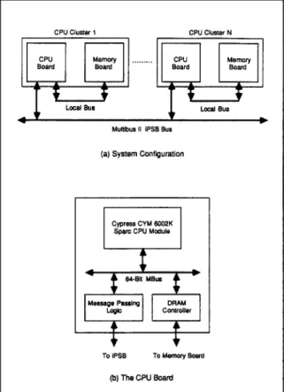
Figure 4 shows the hardware block diagram of the prototype M 2 system. In the prototype ma- chine, the Multibus II [7] is employed as the backplane message-passing bus and each C P U cluster comprises 2 Sparc C P U s [14] along with a 64-megabyte cluster memory. T h e C P U s and the cluster m e m o r y are actually placed on two sepa- rate boards, the C P U b o a r d and the m e m o r y board. T h e C P U b o a r d comprises the CPUs, floating point coprocessors, cache controllers, cache memories, D R A M controller, and mes- sage-passing control logic. T h e m e m o r y b o a r d comprises purelly D R A M chips. T h e C P U b o a r d and the m e m o r y b o a r d are connected through a local bus separate from the Multibus II.
Figure 4(b) shows the block diagram of the C P U board. T h e major functional blocks on the C P U b o a r d are designed around an o n - b o a r d 64-bit MBus [15]. Placed on the u p p e r half of the b o a r d is the Cypress CYM6002K C P U module [16]. T h e CYM6002K consists of 2 Sparc C P U s along with their floating-point coprocessors, cache controllers, and cache memories. Placed on the lower half of the b o a r d is the D R A M controller and message-passing control logic. T h e message- passing control logic is mainly m a d e up of three microcontrollers, an Intel 82389 message passing coprocessor (MPC) [17], an Intel 82380 D M A controller, and an Intel 8751 microcontroller. T h e detailed design of the message-passing control logic is elaborated in the M P C U s e r ' s Manual from Intel C o r p o r a t i o n [17].
3.2. Operating system
T h e prototype M 2 will run the M a c h o p e r a t - ing system [2]. On the prototype M 2, M a c h tasks are dispatched to C P U clusters in their entirety.
multiprocessor 239
In other words, the threads within a task are dispatched only to the C P U s of the cluster that the task is dispatched to and will not spread to other C P U clusters. T h e reason to adopt this strategy is that, as m e n t i o n e d earlier, the C P U cluster provides a natural execution platform for multiple-thread tasks. For tasks that are dis- p a t c h e d to different C P U clusters, the inter-task communication is carried out over the backplane message-passing facility.
4. Conclusion
In this paper, we elaborated the development of the M 2 hierarchical multiprocessor. T h e de- v e l o p m e n t of the M 2 is aimed at meeting the d e m a n d of ever increasing processing power for d a t a b a s e / k n o w l e d g e b a s e computing and transac- tion processing. T h e m 2 features:
• Scalable up to hundreds of CPUs, which is an order of magnitude larger than the scalability of the s h a r e d - m e m o r y shared-bus architecture. • Effectively exploiting the high degree of inte- gration capacity m a d e available by recent ad- vances in V L S I and packaging technologies. • Matching the architecture of m o d e r n multipro-
cessor operating systems such as Mach.
References
[1] S. Thakkar et al., new directions in scalable shared-mem- ory multiprocessor architectures, IEEE Comput. (June 1990).
[2] A. Tevanian Jr., Architecture-independent virtual mem- ory management for parallel and distributed environ- ments: the mach approach, Ph.D. Thesis, Dept. of Com- puter Science, Carnegie- Mellon University, 1987. [3] E. Levy and A. Silberschatz, Distributed file systems:
Concepts and examples, ACM Comput. Surveys 22 (4) (Dec. 1990).
[4] D. Chaiken, C. Fields, K. Kurihara and A. Agarwal, Directory-based cache coherence in large-scale multipro- cessors, IEEE Comput. 23 (6) (June 1990).
[5] A.W. Wilson, Hierarchical cache/bus architecture for shared memory multiprocessors, Proc. 14th Annual Inter- nat. Syrup. on Computer Architecture (1987).
[6] D. Cheriton, H.A. Goosen and P.D. Boyle, Paradigm: A highly scalable shared-memory multicomputer architec- ture, IEEE Comput. (Feb. 1991).
[7] Intel Corporation, Multibus H Bus Architecture Specifica- tion Handbook (Intel Corporation, 1984).
240 Y.J. Oyang et al.
[8] IEEE, IEEE Standard Backplane Bus Specification for Multiprocessor Architectures." Future-bus, IEEE Standard
896.1 (1987).
[9] G.M. Amdahl, Storage and IO parameters and system potential, Proc. IEEE Computer Group Conf. (1970).
[10] Disk cache - miss ratio analysis and design considera- tions, A C M Trans. Comput. Syst. 3 (3) (Aug. 1985).
[11] J.L. Hennessy and D.A. Patterson, Computer Architec- ture: A Quantitative Approach (Morgan Kaufmann, San
Mateo, CA, 1990).
[12] M.G. Baker, J.H. Hartman, M.D. Kupfer, K.W. Shirriff and J.K. Ousterhout, Measurements of a distributed file system, Proc. 13th A C M Syrup. on Operating System Prin- ciples, Pacific Grove, CA (Oct. 1991).
[13] R.H. Katz, S.J. Eggers, D.A. Wood, C.L. Perkins and R.G. Sheldon, Implementating a cache consistency pro- tocol, Proc: 12th Annual Internat. Symp. on Computer Architecture (1985).
[14] Cypress Semiconductor, Sparc RISC User's Guide
(Cypress Semiconductor, 1990).
[15] Cypress Semiconductor, Sparc MBus Interface Specifica- tion, (cypress Semiconductor, 1991).
[16] Cypress Semiconductor, CYM6OO2KDual CPUSparcCore Module (Cypress Semiconductor, 1991).
[17] Intel Corporation, MPC User's Manual (Intel Corpora-
tion, 1986).
Yen-Jen Oyang received the B.S. de- gree in Information Engineering from National Taiwan University in 1982, the M.S. degree in Computer Science from the California Institute of Tech- nology in 1984, and the Ph.D. degree in Electrical Engineering from Stan- ford University in 1988. He is cur- rently an Associate Professor in the Department of Computer Science and Information Engineering, National Taiwan University. His research in- terests include computer architecture and VLSI system design.
David J. Sheu was born on Septem- ber 11, 1967 in Taipei, Taiwan. He received the B.S. degree in Informa- tion and Computer Engineering from Chung-Yuan Christian University in 1990, and the M.S. degree in Com- puter Science and Information Engi- neering from National Taiwan Uni- versity in 1992. His major research interest is multiprocessor architecture and hardware design.
Chih-Yuan Cheng was born on Octo- ber 19, 1968 in Taipei, Taiwan, R.O.C. He received the B.S. degree in Com- puter Science and Information Engi- neering from National Taiwan Uni- versity in 1991. He is currently in the master program of the same depart- ment and expected to complete his degree in 1993. His research field is superscalar architecture and compiler design.
Cheng-Zen Yang is currently a Ph.D. student at the Dept. of Computer Sci- ence and Information Engineering of National Taiwan University, Taipei, Taiwan. He received the B.S. degree in Computer Engineering from Na- tional Chiao Tung University in 1988, and the M.S. degree in Computer Sci- ence and Information Engineering from the same University in 1990. His major research interests include dis- tributed computing system, dis- tributed file system and Operating System.