EFFICIENT ADAPTIVE ARRAY BEAMFORMING
UNDER STEERING ERRORS
Ju-Hong Lee* and Fu-Pong Tong Department of Electrical Engineering
National Taiwan University Taipei, TAIWAN
I. INTRODUCTION
For a linearly periodic array beamformer with size M, the real-time computational requirement associated with the M adaptive weights can be as high as M3 [l]. Moreover, the sensitivity of the adaptive beamformer to steering errors increases as the size M increases [2]. This paper presents an efficient method for adaptive array beamforming with steering vector errors to alleviate the above difficulties. We partition the adaptive array beamformer into several subarrays with size N for each. Due to the fact that data vectors received by any two subarrays have the same envelope waveform except a difference in phase shift, the corresponding optimal adaptive weight vectors also differ only in a phase shift for these two subarrays. Therefore, we compute the optimal adaptive weight vector for one of these subarrays and copy it to the others. When steering errors exist, we utilize a robust algorithm in conjunction with the subarray beamforming technique to find the optimal adaptive weight vector. Simulation results show that the proposed method can cure the degradation effect due to steering errors as well as save computing cost.
JI. BEAMFORMING WITH SUBARRAY PROCESSING
Consider a linearly periodic array with size
M
and interelement spacingU2
(h =the signal wavelength). The optimal weight vector for receiving the desired signal in the steering direction s d while cancelling interference is the solution of the following minimization problemwhere R, = E(X(t)X(t)H) is the MxM correlation matrix corresponding to the received signal vector X(t) of size Mxl. From ( l ) , the optimal weight vector WO is given as [ l ]
where U = 1/SdHR,-’Sd. (2) indicates that the inverse of R, is required for obtaining the optimal weight vector and the computation burden is in the order of
M3.
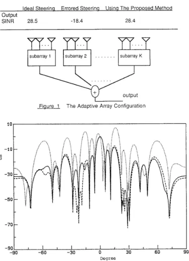
Next, we consider a partition of the array into K nonoverlapping subarrays with size N for each, i.e., M=KN, as shown in Figure 1. Then, the received signal vectors of any two consecutive subarrays have the same waveform function except a phase differenceMinimize ( WHRxW} Subject to WHSd = 1
,
WO = u y l s d I (2)
(1
1
1015
equal to exp(jNrtsin@,), where 8, is the steering angle off broadside. As a result, the steering vectors for the subarrays 1 and 2 are given as S,,= [ 1, eJns'"%,.-., eJ(N-')mlnB]T and Sd2=SdreXp(jNnsin8,), respectively. Performing the adaptive beamforming based on the subarray 1, we obtain the optimal weight vector
where u1 = l/SdlHRxl"Sdl. RXl = E{Xl(t)Xl(t)H} is the NxN correlation matrix of the signal vector XI (t) with size N x l received by the subarray 1. Repeat the beamforming based on the subarray 2. We can show that the optimal weight vector WO2 is similar to (3) except the subscript 1 replaced by 2. Clearly, WO2 = Wolexp(jNrcsin@,). From the above results, it is easy to
see
that the optimal weight vectors for any two consecutive subarrays differ only in a phase shift exp(jNxsin8,) if the array sensor noise is spatially white. Therefore, the output signal Y(t) of the overall adaptive array is given aswio
= UIRX,-'Sdl , (3)K K-1
Y(t) = WbXi(t) = W ~ , X 1 ( t ) ~ exp(jiNxsin8,)
i=l i=O (4)
if we copy the W1, to the other subarrays instead of computing the optimal weight vector for each of the rest subarrays, i.e., let Wio=Wlo, for i=2,3 ,...., K. From (4), we note that the beam pattern of the overall array is the beam pattern of the subarray 1
multiplied by the envelope function given as
K-1
i=O
exp(jiNxsin8,)/'
The envelope function provides (K-1)N zeros (two of them are at sinBS=Ifr2/M), while the beam pattern of subarrayl has N-1 zeros. Hence, the number of total zeros is KN-1 which is the number of beam pattern's zeros (two of them are at sinBS=*2/M) of the original array with size KN. Moreover, the interference is almost cancelled by the subarray 1 if the number of interferers is not greater than N. Therefore, we would expect that the array beam pattern has about the same mainlobe and interference nulling as those of the original array. However, the required computation burden is in the order of N3 instead of M3
111. BEAMFORMING UNDER STEERING ERRORS
Here, we consider adaptive beamforming when steering angle error exists. It is well known that the effectiveness
of
an adaptive array can be destroyed even if a small steering mismatch arises. Let the steering error due t o a small steering angle mismatch cause the tolerance error of s d defined as the squared metric distancesmaller than the squared metric distance of the signal phase vector S and the interferer phase vector
s,,
where sd,m and s, are the mth elements ofS,
andS,
respectively. After the optimal beamforming based on the subarray 1, we have the array output power e(Sdi) =
W ~ o H ~ x ~ W ~ o = ~ / S d ~ H ~ x ~ " S ~ ~
corresponding to theSd,
with the interference being negligible. Hence, the sd, that maximizes the e(Sd,) must be identical to the actual signal phase vectorS.
From this fact, we propose a robust method for dealing with the problem of steering angle error. Consider the following optimization problemor equivalently,
Next, an adaptive algorithm can be used to iteratively adjust the Sdi. Define a tentative update steering vector
(9) where Sdl(n) is the steering vector at
the
nth iteration.P
is a small, positive, step-size parameter which controls the rate-of-change of Sdl.VJ(Sdl) is the gradient of J(sdi) with respect to s d l . Then, we project the result of this iteration onto the constraint boundary(1 0) The algorithm is initiated with sd,(O) = s d , which is the assumed signal phase vector. Once the Sdl is estimated after iterations, we calculate the associated adaptive weight vector for the subarray 1 and copy it to the other subarrays. Consequently, the tolerance error for robustness can be larger in the subarray than in the original array. YI. A SIMULATION FXAMPLE
Maximize e(Sdi) subject to I s d l , m l = 1, m=1,2 ,..., N (7)
Minimize { J(sdi) = SdiHRX,-'Sd} subject to ISdi,,,, = 1, m=1,2, ..., N. (8)
sdl(n+l) = Sdl(n) - P V J ( S d l ) p p S , , ( n ) ,
sdi,,,(n++l) = Sd~,m'(n+l)/Isdi,m'(n+l)l , m = 1,2 ,..., M.
Here, a computer simulation example performed on an MICRO-VAX MV 3600 is presented for illustration. Let the array size M=21, the spatially white Gaussian noise power=l, the SNR=20 dB, the step-size parameter P=O.Ol. An incoherent interferer with interference-to-noise power ratio (INR)=lO dB is at direction angle=30°. The signal arrives at 3O, while the steering angle is Oo, i.e., the steering angle error is 3O. For comparison, Table 1
lists
the output signal-to-interference plus noise power ratios (SINR) for the ideal steering, the errored steering, and the robust processing with 3 subarrays of size 7. Figure 2 shows the array beam patterns for the three cases. From these results, we note that the proposed method can cure the problem of steering angle error with less computation burden for adaptive array beamforming.RFFERFNCES;
[ l ] R.A. Monzingo and T.W. Miller, INTRODUCTION TO RDRPTllIE R R R A Y S , Wiley, New York, 1980.
[2] R.T. Compton, Jr.,"The effect of random steering vector errors in the Applebaum adaptive array", IEEE Trans. Aerosp. Electron. Syst., Vol. AES-18, No.5, Sept. 1982, pp.392-400.
TABLE 1 The Output S INR in dB for Cornoarison
Ideal Steerina Errored Steerina Usina The Prooosed Method Output
SlNR 28.5 -1 8.4 28.4
@
j . . .
”;
I
Fiaure 1 The Adaptive Array Configuration
10 -10 m a -30 -50 -70 -40 -90 -60 -30 0 30 60 Degree I
Fiaure 2 The Array Beam Patterns for the Case of Steering Angle Error. -Ideal Steering,