rol
metho
C.-M. You ng C.-C. Liu C.-H. Liu
Indexing term: Inverters, Two-phase induction motors
Abstract: A simple inverter circuit is proposed for driving symmetrical and unsymmetrical two- phase induction motors. The inverter provides two-phase independently controlled variable- frequency variable voltages to the primary and auxiliary windings of an induction motor. The dynamic model of the two-phase induction motor driven by the inverter is established. An experimental prototype, which consists of a single-chip microprocessor-based controller, the inverter, and the motor and load, is constructed. Both computer simulation and experimental results show the effectiveness of the proposed
inverter-driven motor in achieving higher
performance, such as less torque and speed pulsation and reduced vibration and noise, than the conventional motors.
List of symbols
LS
= source inductanceC, C1, C, = filter capacitance
4
= AC supply currentVc, Vel, Ifc2 = voltages across capacitor
s q ~ , sd$
Tr
v;s,
v2s
= quadrature and direct-axis statori;,, 6 s = quadrature and direct-axis stator
i&!, i$ = quadrature and direct-axis rotor
x s s , x s s = primary and auxiliary-winding stator
Xr,
-KRR =primary and auxiliary-winding rotor= sinusoidal signals for SPWM = triangular signal for SPWM
voltages currents
currents referred to the stator self reactances
self reactances referred to the stator
0 IEE, 1996
IEE Proceedings online no. 19960526 Paper first received 18th September 1995
C.-M. Young and C . 4 . Liu are with the Department of Electrical Engineering, National Taiwan University, Roosevelt Road, Section 4, No. 1, Taipei, Taiwan, Republic of China
C.-H. Liu is with the Department of Electrical Engineering, National Taiwan Institute of Technology, 43 Keelung Road, Sectioii 4, Taipei, Taiwan, Republic of China
X,,, X,,
= primary and auxiliary-winding mutualR,,
R,
= primary and auxiliary-winding statorR:, RK = primary and auxiliary-winding rotor
NJN, = primary-to-auxiliary winding turn ratio ob, or
T,, T,
J , B
vif
= input voltage-to-frequency ratioP
= differential operator1 Introduction
reactances resistances
resistances referred to the rotor
= base speed and rotor shaft speed of the = generated motor torque and load torque = equivalent moment of inertia and viscous
motor
coefficient
In small power applications unsymmetrical two-phase induction motors fed by single-phase supply have been widely used in home appliances and industrial tools. The motors are usually used in fixed speed drives. In situations where variable speed is required, various mechanical or electrical techniques, such as gears, tapped windings, or pole switching, are needed. These methods normally do not achieve continuous control of motor speed. As the input voltage and frequency are fixed irrespective of different operating conditions, the resultant drive performance may also be degraded. In recent years, several methods that use inverters for the variable speed control of single-phase induction motors have been proposed. In [l] an inverter with four switching transistors is proposed for driving two-phase induction motors. The performance of a two-phase induction motor driven by the inverter is discussed in detail in [I], which motivates the inverter design proposed in this paper. Although the inverter in [l] can achieve the variable speed control of two-phase induction motors, it is operated by fixed-frequency square wave, and is supplied by a DC voltage source. No relationship between the utility and the DC voltage source is discussed. [2] and [3] use the same inverter circuit as in [l]. To achieve variable-frequency control, the methods of phase-difference angle control and the selected harmonic elimination PWM technique are used. The advantage of this approach is that the commutation angles of the PWM output voltages are fixed in the entire variable-frequency range. However, under the phase-difference angle control, the generated motor torque of the two-phase symmetrical induction
IEE Proc -Electr Power A p p l , Vol 143, No 6 November 1996
motor studied in [2] and [3] contains double-frequency pulsation torque component, which induces vibration and noise in the drive assembly. In [4] a conventional three-phase inverter is proposed for driving two-phase unsymmetrical induction motors, in which six power transistors are used. In [5] an inverter circuit composed of eight power transistors is proposed for driving two- phase induction motors. Compared to the inverter circuits presented in [4, 51, the inverter in [l] has simpler circuit structure, lower component cost, and the simplest switching control method. In [6] a method is proposed for the variable speed control of a single- phase induction motor. The main motor winding is supplied from the utility and the auxiliary winding is energised by a fixed-frequency, variable-voltage, variable-phase-angle voltage source. The resultant operating speed range is quite limited. In [7] the torque and slip behaviour of a single-phase induction motor driven from a variable-frequency supply is studied. Although useful information of operating single-phase induction motors under variable-frequency voltage source is provided, the results are based on the condition that the input power to the motor main winding is supplied not by an inverter but by a synchronous generator.
For a two-phase induction motor driven by an inverter, the conventional devices such as centrifugal switches, starting, and run capacitors can all be eliminated. The advantages are the increasing motor reliability due to the elimination of mechanical devices, increasing system efficiency, and better dynamic performance due to variable-speed operation. Another benefit is the reduction of acoustic noise and torque pulsation effects. In a conventional two-phase induction motor, in order to obtain good starting and running performance and to operate the motor from a single-phase source, the motor is usually designed to have unsymmetrical two-phase windings. The resultant torque consists of an average developed torque and a pulsating torque which induces mechanical vibration and audible acoustic noise in the motor and load assembly [8]. By varying the frequencies and magnitudes of the two-phase stator voltages, the torque pulsation and noise effects can be reduced. An example is the inverter-driven control of a room air conditioner This paper presents the design and implementation of an inverter-driven two-phase induction motor drive. The proposed method is applicable to both
symmetrical and unsymmetrical-type two-phase
induction motors.
The design of the inverter, presented in Section 2, is based on the considerations that it has a minimum number of power devices and it has the potential of being fabricated into an control-and-power integrated circuit (IC) [lo] for use in practical applications. To aid the design and to evaluate the performance of the pro- posed inverter-driven motor drive, state-space equa- tions describing the motor dynamics are formulated. The control of the inverter is based on the constant Vlf strategy. The inverter generates two-phase, variable fre- quency, variable voltages to the motor. The magnitude and phase difference between the two phase voltages are controlled so as to reduce the torque pulsation effect. A conventional sinusoidal pulsewidth modula- tion (SPWM) is used to modulate the two phase volt- age waveforms. A simulation model consisting of the 191.
IEE Proc -Electr. Power AppL, Vol. 143, No. 6, November 1996
inverter, the induction motor, and load is developed to aid the design of the drive control system.
To
evaluate the performance of the proposed approach, computer simulation is presented in Section 3. The performance evaluation is based the steady-state torque and speed ripples. The simulation results show improved perform- ance of the proposed drive as compared to the existing drives. An experimental prototype, presented in Section 4, is further constructed to verify the actual perform- ance. The implemented system consists of a single-chip microprocessor-based controller and an inverter with IGBT modules. The experimental results also show improved performance of the proposed method.a
l
l
,
0
3
C
,
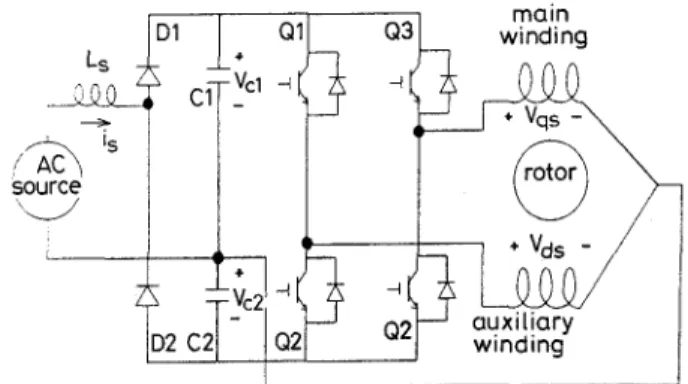
winc maFig. 1 Schematic diagram ofproposed inverter
2 Inverter design
Fig. 1 shows the inverter circuit diagram proposed ~
in this paper. The inverter consists of-,a single-phase voltage-doubler rectifier, two filter capadtors in series, two pairs of power transistors, and an input inductor which is used for improving the power factor of the ac source. The centrepoints of the two pairs of power transistors are connected, respectively, to each one of the terminals of the main and auxiliary windings. The rest two terminals of the main and auxiliary windings are connected together to the centre-tap of the series capacitors. In terms of the number of circuit elements, the proposed circuit in Fig. 1 has the same number of switching elements as those proposed in [l-31 on the inverter side and fewer switching elements than those of the circuits of [4, 51. The rectifying circuits were not addressed in [1-4]. In [5] a full-wave bridge rectifier is used, which has two more diodes than the one in Fig. 1. The trade-off is that, under the same loading conditions and capacitance values, the voltage ripples of the capacitors in Fig. 1 are larger than those of the full-wave bridge rectifier. As can be seen from Fig. 1, the common terminals of the two motor windings are connected directly to the source. The return currents of the two windings are fedback to the source, whose frequencies are different from the source, since the current frequencies of the two windings are varied by the inverter. However, the source current flows only when the rectifying diodes are conducting. The conduction time of the rectifying diodes is fairly short when compared to the period of the input supply [l 11.
To assess the effects of motor return current on the source, the circuit performance of Fig. 1 is compared to that of the circuit shown in Fig. 2, which consists of a full-wave diode-bridge rectifier, a filter capacitor, and two sets of full-bridge single-phase inverters. The two inverters in Fig. 2 provide separate variable-frequency, variable-voltage source to the primary and auxiliary windings of the motor. The circuit shown in Fig. 2 has
far more circuit elements than those in Fig. 1, it serves as a basis for performance comparison with the circuit of Fig. 1. The performance of the circuits in both Fig. 1 and Fig. 2 is evaluated using computer simulation.
31
4 Q1' -1 t vc-
mainI-
I 1 I I I I I- 2 Inverter circuit for comparing with Fk. I
0.80 0.81 0.82 0.83 -3 SP WM technique Waveforms of Sqs, S,,, and T, 200 1 -200
I
I I I I I I 0.82 0 83 0.80 0.81 SP WM technique Inverter output V, -200-1- 1 , I 0 80 0.81 0.82 0.83 t,S .5 SP WM technique Inverter output VdThe input source for both circuits in Fig. 1 and Fig. 2 z. The capacitance values are C1 = C2 = C = 2000pF and the source inductance Ls = ImH. The motor parameters are given in Table 2, Section 3. Both inverter circuits use constant V7f control strategy and
sinusoidal pulsewidth modulation (SPWM). The two- phase modulating signals are generated by comparing separately the two sinusoidal waves, Sq,(t) and Sds(t),
with a phase difference of 90", to a triangular carrier wave Tr(t). At any instant of time, when Sqs(t) is greater than Tr(t), Ql is ON and Q2 is OFF in Fig. 1, while (Qi,
a)
are ON and (Q;, Qi) are OFF in Fig. 2.When Sq,(t) is less than Tr(t), the turn-on and turn- off switches are reversed. The same modulation method is applied to Sds(t) and Tr(t), in which the correspond- ing switching elements are Q2 and Q3 in Fig. 1 and (2; to Qlin Fig. 2. Fig. 3 shows the waveforms of S,,(t),
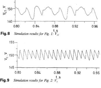
Sdr(t) and Tr(t). The inverter output waveforms, V,,(t) and Vds(t), are also shown in Figs. 4 and 5. It should be noted that both inverters have the same output characteristics, only the input rectifying characteristics can be used to differentiate the two inverters. To eval- uate the performance of the two inverters on the input rectifier side, the performance indices such as the source total harmonic distortion (THD), the power fac- tor (PF) and the ripple factor (RF) are employed [12]. The ripple factor is used to evaluate the voltage wave- form across the capacitors. Table 1 summarises the simulated results when the inverters are operated at 60, 45, and 30Hz, respectively. Fig. 6 and Fig. 7 show the respective source current waveforms, is(@ The capaci- tor voltage waveform, Vcl(t), in Fig. 1 is shown in Fig. 8, while the capacitor voltage waveform, Vc(t), in Fig. 2 is shown in Fig. 9. Comparing the results given in Table 1 and Figs. 6, 7, 8 and 9, the inverter shown in Fig. 2 clearly performs better than the proposed inverter in this paper. The reason is clear, since the proposed inverter has fewer power elements than the inverter of Fig. 2. However, the performance of the proposed inverter can be improved by incorporating the power factor correction technique.
two input rectifying diodes in Fig. 1 by two power transistors and employing an appropriate power factor correction (PFC) circuit, such as the one given in [13], the THD, PF and R F can all be improved significantly, which are also tabulated in Table 1.
-10 j I I I I 1 I I I
0.80 0.84 0 88 0 92 0 96
t ,s Simulation results for Fig. 1: is
-l o -0.80 0.84 0.88 0 92 0 96 1.5
Simulation results for Fig. 2: is
.7
Operation frequency Proposed inverter Inverter in Fig. 2 Proposed inverter with PFC
f, Hz THD,(%) PF,(%) RF,(%) THD,(%) PF,(%) RF,(%) TWD,(%) PF,(%) RF,(%)
60 120 67.1 1.21 108 71.1 0.89 9.8 99.3 0.97
98.7 1.45
45 125 60.3 1.91 117 61.3 0.79 11.8
30 '1 55 52.6 2.71 134 58.7 0.52 16.2 98.4 1.94
IEE Proc -Electr Power Appl, Val 143, No 6, November 1996
l 6 O l
0.80 0.84 0.88 0.92 0 96
t.s
Simulation resultsfor Fig. 1: Vci
Fig.8 155-
1
zL1501
1452
.
0 80 0.84 0.88 0.92 0.96 t . sSimulation resultsfor Fig. 2: V,
Fig.9
3 Modelling, control and simulation
3.1 Motor dynamic equations
The state-space dynamic equations for a two-pole, two- phase, unsymmetrical induction motor are formulated in the stationary reference frame as [14]
where the subscripts s, S , r and R denote the unsymmetrical stator and rotor windings. For the symmetrical case, X,, = Xss and others similarly apply. For starting purpose, a capacitor is usually connected in series with the auxiliary winding of the motor. The term P / O b x , , given in eqn. 1 is replaced by p / O b x ,
+
ob/pXc. Let z = i&/p, which can be augmented with eqn. 1 to form a complete set of equations for describing the motor dynamics with a starting capacitor. The generated motor torque is
and the electromechanical equation is
(3) 2
P
J-pwT
+
Bw,+
TL = TeThe dynamic equations of the unsymmetrical two- phase induction motor are more complicated than those of the symmetrical three-phase induction motor. The unsymmetrical winding arrangement in the two- phase induction motor causes greater torque and speed fluctuations. However, both the symmetrical two-phase and three-phase induction motors have similar performance.
Table 2: Induction motor parameters
3.2 Control
of
the inverterThe inverter generates two-phase, variable-frequency, variable-voltages to the primary and auxiliary windings of the motor. The constant Vlf strategy is used to
determine the output voltage magnitude based on the input speed (i.e. frequency) command. The two-phase voltage output waveforms have a phase difference of 90" and are modulated using the sinusoidal pulse width
modulation (SPWM). Based on the symmetric
component concept, the condition for the motor to have zero torque pulsation is to operate the motor with two-phase excitation having a 90" phase relation and the current amplitude in inverse ratio to the machine turns [6]. A further approximation to achieve the condition of zero torque pulsation is to generate two- phase voltages having a 90" phase difference and the
primary-to-auxiliary voltage-magnitude-ratio is
inversely proportional to the machine turns [6]. Notice that, for the unsymmetrical two-phase induction motor, the auxiliary winding has higher voltage level than the primary winding and, consequently, the primary winding has higher current level. This type of operation is different from a conventional motor which normally has balanced two-phase currents. However, the proposed approach results in less torque pulsation and noise. Thus, to apply the proposed inverter to a conventional motor without altering its original construction and winding arrangement, the voltage and current ratings of the motor windings must be carefully evaluated.
The same inverter can also be applied to a symmetrical two-phase induction motor with better performance. Both windings of the motor have the same level of voltages having a 90" phase difference. The resultant phase currents are also balanced and a smooth generated torque is obtained. This is then identical to the case of a balanced three-phase induction motor driven by a three-phase inverter.
3.3 Computer simulation
In many applications employing the two-phase induction motors, the loads usually exhibit nonlinear characteristics, such as the rolling-piston type compressor commonly found in a room air conditioner. However, the dynamic equations of these nonlinear loads contain many design parameters which are not easily obtainable from the manufacturers. The simulation results presented in this section are all based on the constant load torque assumption. Still these results provide an assessment on the effect of the inverter in reducing the motor torque pulsation.
To evaluate in-depth the various characteristics of an inverter-driven motor drive, several operational modes are chosen for a comparison, which all use the same induction motor with unsymmetrical two-phase wind- ings. The motor parameters are tabulated in Table 2 and the ratings are IlOV, 6OH2, 1/4HP, and four-pole. In all simulated cases, the load torque is fixed at 1 N m.
The operational modes are described in the
R, = 2.02 8 R, = 7.14 B R:=4.12 B R+ 5.74 51 RCS = 3 B
Xr= = 2.79 B XIS= 3.22 !2 X,,,, = 92.9 S2 X:,= 2.12 P Xk= 2.95 B
X C R = 1 7 2 B R c R = 9 B J=0.0146kg/m2 NJN,=1.18 X m S = 6 6 . 8 P
XcS = 14.5 P
following:
Case 1: The motor is a capacitor-start type with a
centrifugal switch. The input supply is single-phase. During iiormal running condition, only the primary winding is energised.
Case 2; The motor is a split-phase type and the input
supply is single-phase. The capacitance of the run capacitor is 183pF.
Case 3: The motor is also a split-phase type. The input
supply is single-phase. The capacitance is 15.4@.
Case 4: The motor is driven by an ideal two-phase
variable-frequency variable-amplitude sinusoidal
voltage source. No start or run capacitors are used. The phase difference between the two voltages is 90". This operating mode serves as a reference for comparing with all other cases.
Case 5: The motor is driven by a two-phase variable-
frequency, variable-voltage PWM inverter, shown in Fig. 1, with the carrier frequency set at 7.2kHz. The capacitance values are C1 = C2 = 2000pF and the source inductance L3 = 1mH. No start or run capacitors are used.
170 172 174 1 76 178 180
t.s
Simulatedspeed response for case 3
Fig. 10
1 4 4 0 7
The resultant slips for all the simulated cases are shown in Fig. 14. Also, let Amr be the variation between the peak and the lowest speeds of the steady-state speed response in each case. The speed variations for all the cases are shown in Fig. 15. As shown from the simula- tion results, the proposed approach, case 5 , shows bet- ter performance than the existing motor drives, cases 1-3, and has comparable performance to case 4. Case 5 has smaller slips and speed variations in the frequency range from 45 to 60Hz. As the frequency is reduced from 45 to 30Hz, the slip in case 5 increases to main- tain the rated torque. The corresponding primary line current will also increase due to the increase in slip, which is shown in Fig. 16. These results are identical to the ones presented in [7].
1
Fig. 13
-+- case 1, capacitor start
--- case 2, capacitor run (CR = 183 pF) -*- case 3, capacitor run (CR = 15.4pF)
--
case 4, two-phase (Sine source) -x- case 5, two-phase (inverter)Simulated average speeds for cases 1-5
1425
1
,
1 70 172 174 176 1 78 180
t . 5
Simulated speed vesporise for case 4
Fig. 11 1435
1
C I 1 4 2 0 1 ,,
I I , ,,
,,
170 1 72 1.74 1 7 6 1.78 1 8 0 t.s,%udatedspeed response for case 5
Fig. 12
For cases 4 and 5, the ratio of primary-to-auxiliary voltage magnitude is set equal to NJ/NS The input frequencies are varied from 35 to 60Hz with an increment of 5Hz. F o r f = 50Hz, the speed responses for cases 3, 4, and 5 are shown in Figs. 10, 11 and 12. The average speed, wave, defined as the mean of the peak and lowest speeds of the steady-state speed response, is calculated for each case and is shown in Fig. 13. Define the synchronous speed we = 2zf and the slip wSl as 1 1 I I I I I I I , 1 35 40 45 50 55 60 f. Hz Fig. 14
-t- case 1, capacitor start
--- case 2, capacitor run (CR = 183 pF)
-*- case 3, capacitor run (CR = 15.4pF)
-0- case 4, two-phase (Sine source)
-x- case 5 , two-phase (inverter)
Simulated average slips for cases 1-5
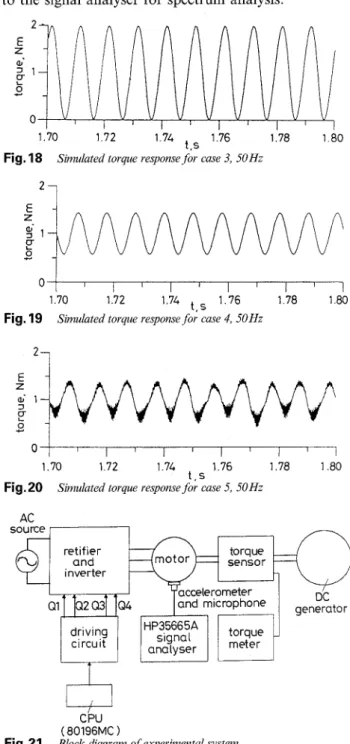
The torque variation, which is defined as the differ- ence between the peak (highest) to peak (lowest) torque values in a steady-state torque response, is computed for each case and is summarised in Fig. 17. Again, the torque variation in case 5 is almost identical to that of case 4 and is the smallest as compared to cases 1-3. Finally, the steady-state generated motor torque and load torque responses for cases 3, 4, and 5 are shown in Figs. 18, 19 and 20. The proposed approach, case 5, shown in Fig. 20 reduces the generated torque pulsa- tion quite effectively as compared to the conventional IEE Proc -Elect7 Power A p p l , Vol 143, No 6, November 1996
approach, case 3. In fact, the responses of case 5 and case 4 are almost identical.
driving circuit
0 0
35 40 45 50 55 60
f,Hz case 2 , capacitor run (CR = 183 pF) case 3, capacitor run (CR = 15.4 pF) case 4, two-phase (Sine source)
Fig. 15
-+- case 1, capacitor start
-._
-*-
-0-
-x- case 5, two-phase (inverter)
Simulated peak-to-peak speed variationsfor cases 1-5
0 Q C . 4 c E
a
HP35665A torqueana,yser signal meter
-
40 45 50 55 60
f.Hz
35
Fig. 16
-+- case 1, capacitor start
-.-
-e
-x- case 5, two-phase (inverter)
Simulatedprimary stator line currentsfor cases 1-5
case 2, capacitor run (CR = 183 pF)
case 4, two-phase (Sine source)
_ _ * case 3, capacitor run (CR = 15.4 pF)
-
-
" v " e o r , 1 I " L i l r l i 35 40 45 50 55 60 f,Hz Fig. 17-+- case 1, capacitor start
-.-
-*-
-0-
-x- case 5, two-phase (inverter)
Simulated torque variationsfor cases 1-5
case 2, capacitor run (CR = 183 pF)
case 3, capacitor run (CR = 15.4 pF) case 4, two-phase (Sine source)
4 Implementation and experimental results
To verify the proposed inverter-driven control strategy for two-phase induction motor drives, an experimental prototype is implemented. The block diagram of the IEE Proc-Electr. Power Appl,, Vol. 143, No. 6, November 1996
experimental system is shown in Fig. 21. The motor used in the experiments has unsymmetrical two-phase windings with removable start and run capacitors and centrifugal switches according to the experimental needs. The primary-to-auxiliary turn ratio is M.3. The ratings of the motor are llOV, 60Hz, four-pole, 1/2 HP. The motor is coupled to a 400W DC generator, which, by adjusting its field voltage, provides variable load torque to the motor. To measured the torque responses, a torque sensor is mounted on the same shaft which couples the induction motor and DC generator. The shaft speed is also measured using a tachometer. To further record the effect of torque pulsation, a portable type accelerometer which can be magnetically attached to the motor frame is used. The accelerometer measures the mechanical vibration and sends the signal to the HP35665A signal analyser for spectrum analysis. The vibration spectrum provides an evaluation of torque pulsation effect. A microphone is also installed at a distance of 3cm from the motor. The noise signals generated from the drive system are sent to the signal analyser for spectrum analysis.
2 E Z d ' 1
e
c 0 1.70 1.72 1 .?4 1.76 1.78 1 0 0 t.5Fig. 18 Simulated torque response for case 3, 50Hz
21
1.70 1.72 1.74 1.76 1.78 1.80
t. 5
Fig. 19 Simulated torque response for case 4, 50Hz
E d 1
P
z c 1 I I ISimulated torque response for case 5, 50Hz
I I I I I
1.70 1.72 1.7L 1.76 1.78 1.80
t . 5
The motor is driven by the inverter shown in Fig. 1. The input AC voltage to the inverter is llOV, 60Hz. The inverter consists of a half-bridge rectifier, two series capacitors C1 = C2 = 2000pF and two-pairs of IGBTs. The inverter provides two-phase, variable- frequency, vanable-voltages to the primary and auxiliary windings of the motor. The control of IGBT
switching is determined by a single-chip
microprocessor, the INTEL 801 96MC. According to the constant
Vif
(= 1.83) strategy, the microprocessor computes the desired voltage magnitudes based on the input frequency (i.e. speed) command. The two-phase voltage output waveforms are modulated, using the build-in SPWM function in the microprocessor. The triangular (carrier) frequency for SPWM is set at 4.8 kHz. The magnitude ratio between the two-phase output voltages is the primary-to-auxiliary turn ratio and the phase difference is kept at 90". The primary voltage phasor is d2 x 110 L O"/A, where A = 1.3 is the turn ratio and the auxiliary voltage phasor is d2 x 110L
90". 1 I 1 I I I I I I I I 35 40 45 50 55 60 f, Hz Fig. 23Measured average slips -+- case 1, capacitor start
-.-
-*-
-0-
-x- case 5 , two-phase (inverter)
Measured speed responsesfor cases 1-5
case 2, capacitor run (CR = 75pF) case 3, capacitor run (CR = 20fl) case 4, two-phase (Sine source)
The five cases that are studied in the simulation are also experimentally verified. The DC generator is used to provides a constant 0.84N m load torque to the motor. The power source for cases 1 4 is provided by a programmable AC power supply. Only in case 5 is the
8o
1
U E E
-
6ol
35 40 45 f,Hz 50 55 60
Fig. 24
Measured peak-to-peak speed variations
-f-
-.-
case 1, capacitor start -*--&
-x- case 5, two-phase (inverter)
Measured speed responses for cases 1-5
case 2, capacitor run (CR = 75p.F) case 3, capacitor run (CR = 2 0 p ) case 4, two-phase (Sine source)
0
35 40 45 50 55
Measuredprimary stator currents for cases 1-5 f , Hz
Fig. 25
-+- case 1, capacitor start
-.-
-*_
-0-
-x- case 5 , two-phase (inverter)
case 2, capacitor run (CR = 75pF) case 3, capacitor run (CR = 20p.F) case 4, two-phase (Sine source)
motor driven by the inverter. In all cases, the operating frequencies are varied from 35 to 60Hz with an increment of 5Hz. Fig. 22 shows the measured average speeds, wave, at the five operating frequencies, in which
cases 4 and 5 have almost the identical performance. The average slips, defined in eqn. 4, are summarised in Fig. 23, in which case 5 closely follows case 4. The peak-to-peak speed variations are shown in Fig. 24, in which case 5 is closest to case 4. The RMS values of the primary stator current at steady-state are shown in Fig. 25, in which cases 4 and 5 have the lowest currents. The vibration and noise signal levels are measured and are shown in Fig. 26 and Fig. 27, respectively. Fig. 28 shows the measured source current i, and capacitor voltage Vcl waveforms for case 5 at 50Hz. The experimental results of Fig. 28 and the simulation results given in Figs. 6 and 8 are quite close. Fig. 29 shows the two winding current waveforms of the motor, also for case 5 at 50Hz. The speed ripple responses for case 3, 4, and 5 at 50Hz are shown in Fig. 30. All three cases exhibit double frequency (l00Hz) pulsating components, among them case 5 has smaller pulsating component than that of case 3. Finally, Fig. 31 and 32 show the noise spectrums for case 3 and 5 at 50Hz. A high level noise component can be found at 100Hz in case 3, while the noise
IEE Proc.-Electr. Power AppL, Vol. 143, No. 6, November 1996
component of the same frequency in case 5 is mostly attenuated. Thus the experiments have clearly shown that the proposed inverter-driven motor drive can effectively reduce vibration and noise levels.
35 40 45 50 55 60
f , Hz
Fig.26 Meamred vibration signal levels -+- case 1, capacitor start
-.-
case 3, capacitor run (CR = 2 0 s )
-0
-x- case 5, two-phase (inverter)
case 2, capacitor run (CR = 75wF)
case 4, two-phase (Sine source) _ - *
-40
7
35 40 45 50 55 60
f, Hz Fig. 27
-+- case 1, capacitor start
-.-
-*-
-0
-x- case 5 , two-phase (inverter)
Measured noise signal levels
case 2, capacitor run (CR = 7 5 p)
case 3, capacitor run (CR = 20m)
case 4, two-phase (Sine source)
. . . . . . . . . . . . ( i i ) . . . . . . . . . . .
Fig.28 Measured resultsfor case 5
(i) AC source current is (10 Aidiv) (ii) Voltage ripple of Vcl ( 5 Vidiv)
5 Conclusions
A simple inverter circuit has been proposed for driving the two-phase induction motors for both symmetrical and unsymmetrical types. The inverter is designed to have a minimal number of circuit components and is
IEE Proc-Elect?. Power Appl., Vol. 143, No. 6, November 1996
digitally controlled. The inverter provides independ- ently-controlled variable frequency, variable-voltages having a 90" phase difference to the primary and auxil- iary windings of the two-phase induction motor. The two-phase voltages are independently controlled by the constant Vlf strategy and are sinusoidal pulse-width- modulated. Both computer simulation and experimen- tal results have shown the effectiveness of the proposed inverter-driven motor drive in reducing torque pulsa- tion and speed variation as compared to conventional approaches. The experiments also show that the associ- ated vibration and noise levels are reduced.
. . . . . . . . . . . . . . . . . . . , . . . . . . . . . . . . . . . . . . . . . . I .. . . . I . . Fig.29
(i) Main winding current (5 A/div) (ii) Auxiliary winding current ( 5 Aidiv)
Measured motor winding currents,for case 5 at 50 Hz
. . . . . . . . . .
t
. . . . . .. . . . . Fig.30 (i) Case 3 (ii) Case 4 (iii) Case 5Measured speed ripple responses for cases 3-5 at SO Hz
t
5
-60-80
0 100 200 300 400
f , Hz
Fig.31 Memured spectrum of noise signal: Case 3
m
9
-401
Ti
-60h
*0 100 200 300 400
f, Hz
Fig. 32 Measured spectrum of noise signal: Case 5
With the rapid advancement in microelectronics tech- nology, the design of a control-and-power application specific IC based on the architecture presented in this paper is feasible. By combining the control-and-power chips with the current small-power two-phase induction motors, the drive performance can be greatly improved.
6 Acknowledgments
This research was partially supported by the National Science Council, Taiwan, under grants NSC82-0416-E- 01 1-096 and NSC83-0416-E-011-001.
References
MHANGO, L.M.C., and CREIGHTON, G.K.: ‘Novel two- phase inverter-fed induction-motor drive’, IEE Proc. B, 1984, 131, (31, pp. 99-104
JANG, D., CHA, G., KIM, D., and WON, J.: ‘Phase-difference control of 2-phase inverter-fed induction motor’. IEEE Industrial Applications Society annual meeting conference records, 1989, pp. 571-578
JANG, D.-H., and WON, J.-S.: ‘Voltage, frequency, and phase- difference angle control of PWM inverters-fed two-phase induc- tion motors’, ZEEE Trans. Power Electron., 1994, 9, (4), pp. 377- 383
4 HOLMES, D.G., and KOTSOPOULOS, A.: ‘Variable speed con- trol of single and two phase induction motors using a three phase voltage source inverter’. IEEE Industrial Applications Society annual meeting conference records, 1993, pp. 613-620
5 ALEXA. D.: ‘Static frequency converter for supplying an asyn- chronous two-phase motor’, ZEE Proc. B, 134, (I), pp. 57-60 6 COLLINS, E.R., PUTTGEN, H.B., and SAYLE, W.E.: ‘Single-
phase induction motor adjustable speed drive: direct phase angle control of the auxiliary winding supply’. IEEE Industrial Applica- tions Society annual meeting conference records, 1988, pp. 246- 252
7 COLLINS. E.R.: ‘Torque and slip behavior of single-phase induction motors driven from variable-frequency supplies’, IEEE Trans. Ind. Appl., 1992, 28, (3), pp. 710-715
ZHU, Z.Q., and HOWE, D.: ‘Vibrational torques in single-phase induction motors and their relation to vibration and noise, Elec- tric Mach. Power Syst., 1992, 20, pp. 483492
9 YOUNG, C.-M., LIU, C.-C., and LIU, C.-H.: ‘Vibration analy- sis of rolling piston-type compressors driven by single-phase induction motors’. IEEE international conference on Industrial electronics, control and instrumentation, 1993, pp. 918-923 10 NISHIHARA, M.: ‘Power electronics diversity’. Proceedings of
1990 international Power electronics conference, 1990, pp. 21-28 11 SEDRA, A.S., and SMITH, K.C.: ‘Microelectronic circuits’ (CBS
College Publishing, 1987)
12 RASHID, M.H.: ‘Power electronics: circuits, devices, and appli- cations’ (Prentice-Hall, 1993)
13 BOYS, J.T., and GREEN, A.W.: ‘Current-forced single-phase reversible rectifier’, ZEE PYOC. B, 1989, 136, (9, pp. 205-211 14 KRAUSE, P.C.: ‘Analysis of Electric Machinery’ (McGraw Hill,
New York, 1987) 8