- 0 -
國
立
交
通
大
學
光電工程研究所
碩 士 論 文
高動態對比演算法用於免彩色濾光片免偏振
片之節能顯示器
A High Dynamic Range technology for Color-filter Less
and Polarizer-free Eco-display
研 究 生:謝毅翰
指導教授:黃乙白 博士
- 1 -
高動態對比演算法用於免彩色濾光片免偏振
片之節能顯示器
A High Dynamic Range technology for Color-filter Less
and Polarizer-free Eco-display
研 究 生:謝毅翰 Student:Yi-Han Hsieh
指導教授:黃乙白 Advisor:Yi-Pai Huang
國 立 交 通 大 學
光 電 工 程 研 究 所
碩 士 論 文
A ThesisSubmitted to Institute of Electro-Optical Engineering College of Electrical and Computer Engineering
National Chiao Tung University in partial Fulfillment of the Requirements
for the Degree of Master
in
Electro-Optical Engineering June 2010
Hsinchu, Taiwan, Republic of China
i
高動態對比演算法用於免彩色濾光片免偏振
片之節能顯示器
碩士研究生:謝毅翰 指導教授:黃乙白副教授
國立交通大學電機學院 光電工程研究所
摘 要
近年來能源的問題愈來愈嚴重,但液晶顯示器的出光效率卻不到 10%。從一 開始的背光模組到電晶體、彩色濾光片、偏光片、液晶層等,每一個元件都會降 低顯示器的出光效率,然而,在這些元件裡,又以偏光片和彩色濾光片的出光效 率最差,因此若可以去除偏光片和彩色濾光片的話,出光效率可達到將近 40%。 目前,時序型顯示器可成功地移除彩色濾光片,而高分子分散液晶材料(PDLC) 可在不用偏光片的情況下讓液晶產生對比,本論文提出的節能顯示器是建立在時 序型顯示器與高分子分散液晶材料的基礎上且結合使用發光二極體的光源,進而 提出一高動態對比的技術(High Dynamic Range technology)以維持影像品質。 在有使用此高動態對比的技術平均的表現都會比沒有使用此高動態對比的技術 來的好,且在高分子分散液晶材料的對比愈小時,兩者的差距愈大。另外,在有 使用此高動態對比技術的人因實驗結果裡,當高分子分散液晶材料的對比高於 70:1 時,人眼均感覺不出差別,而此時的平均色差僅在 0.5 左右,色差大於 3 的百分比約為 3%。另外,在移除了彩色濾光片與偏正片之後,本論文更引入了 120Hz Stencil-FSC 法和白光發光二極體,當白光發光二極體的效率在 100lm/W 的狀況下,與傳統的時序型顯示器比較,此節能顯示器的耗光量更可大幅降低至 原先的 13%。ii
A High Dynamic Range technology for Color-filter Less
and Polarizer-free Eco-display
Student: Yi-Han Hsieh Advisor: Dr. Yi-Pai Huang
Institute of Electro-Optical Engineering National Chiao Tung University
Abstract
In recent years, the energy concerns are increasing around world. However, the optical throughput of the liquid crystal display (LCD) is less than 10%. The backlight module, the TFT array, the color filter, the polarizers, and the liquid crystals reduce the optical throughput. Moreover, the color filter and the polarizers are the two elements wasting the most light. Thus, lacking the color filter and polarizers, the LCD can enhance the optical throughput to 40%.
The FSC-LCD successfully removes the color filter, and the polymer dispersed liquid crystal (PDLC) does not need the polarizers. The thesis will propose an Eco-display. Based on the FSC-LCD and the PDLC concepts, the thesis will propose a High Dynamic Range (HDR) technique, the Contrast Dependent Dimming Method, by using the LED light source to maintain the image quality. The simulation results show the image quality is better with the Contrast Dependent Dimming Method. When the contrast of PDLC becomes lower, the Contrast Dependent Dimming Method modifies the image quality more. Besides, the psychophysical experiment results show that when the contrast ratio becomes lower than 70:1, the human vision
iii
system starts feeling the differences. The psychophysical experiment result corresponds to the average Δ E=0.2 and 3% Δ E>3. Moreover, the thesis will further incorporate the 120Hz Stencil-FSC and the white LED. Assuming the efficiency of the white LED is 100lm/w, the Eco-display can further reduce the optical power to 13% of the convention FSC-LCD.
iv
誌 謝
首先誠摯的感謝指導老師謝漢萍教授和黃乙白副教授,在這碩士兩年的求學 中對於研究態度及英文能力的教導,不僅提供豐富的資源與完善研究環境,使我 得以在碩士生涯提升了專業及英文的能力,並且順利完成此論文。此外,也感謝 各位口試委員所提供的寶貴意見,使本論文更加的完備。 在此特別感謝吳政育學長對於論文的指導,其細心的指導方式,嚴謹的研究 態度,讓我不僅只在研究上的學習成長,更在做人處世上受益良多。 在實驗室的日子裡,感謝有鄭榮安、林芳正、鄭裕國、許精益、蔡柏全、王 奕智、廖凌堯、張育誠、陳志維等學長們提供各方面的指導與協助,也感謝宜如、 宗緯、佑禎、拓江、靖堯、博文、俊賢、浩彣、宜伶、高銘、益興等學長姊們讓 我的生活更加精彩。同時感謝期竹、世勛、景文、璧丞、裕閔、怡菁、耆賢、姚 順、甫奕、詠材等同學們在課業、研究、生活上的幫助與分享,並伴我一起度過 兩年碩士班的日子。我也感謝實驗室的學弟妹們與助理小姐,感謝你/妳們的幫 忙及讓實驗室充滿歡愉的氣氛。 最後,對於我的家人與女朋友,我要感謝你們多年來的支持與鼓勵以及生活 上的細心照顧,使我能無後顧之憂的研究與學習,並順利完成碩士學位。這份喜 悅與榮耀我將跟所有我所認識的各位分享。v
Table of Contents
Abstract (Chinese) ...i
Abstract (English) ... ii
Acknowledgement
...…………...………...………...iiiTable of Contents ... v
Chapter 1 ... 1
1.1 Thin Film Transistor Liquid Crystal Display (TFT-LCD) ... 1
1.2 TFT-LCD Issues ... 3
1.3 Motivation and Objective... 5
1.4 Organization of This Thesis ... 6
Chapter 2 ... 7
2.1 Color-filter-less Liquid Crystal Display... 7
2.1.1 Color Break-up Phenomenon ... 9
2.1.2 Methods to Suppress CBU ... 11
2.1.3 Two Field Method ... 12
2.2 Polarizer-free LCD ... 13
2.2.1 Polymer-dispersed Liquid Crystal Display (PDLC display) ... 14
2.2.2 Dye-doped PDLC... 15
2.3 Color Matching Model and CIEDE2000 ... 16
2.3.1 Color Matching Model ... 17
2.3.2 CIEDE2000 for Evaluating Color Difference ... 18
2.4 Summary ... 20
Chapter 3 ... 21
3.1 Concept ... 21
3.2 Contrast Dependent Dimming Method ... 23
3.3 Contrast Dependent Dimming Method Applied to FSC ... 25
3.3.1 The Applied FSC method—The Two Field ... 26
vi
3.4 Summary ... 29
Chapter 4 ... 30
4.1 Picture Classifier ... 30
4.1.1 Hue ... 30
4.1.2 The Construction of the Picture Classifier ... 31
4.1.3 The Pictures Chosen for Simulation ... 34
4.2 Simulation ... 35
4.2.1 Backlight Division ... 36
4.2.2 With the Contrast Dependent Dimming Method VS Without the Contrast Dependent Dimming Method ... 37
4.3 Discussion-- Clipping and Saturation ... 41
4.3.1 The Clipping in Brightness ... 41
4.3.2 The Saturation ... 42
4.4 Summary ... 43
Chapter 5 ... 44
5.1 The Simulation of the color difference ... 44
5.2 Optimization from a Psychophysical Experiment ... 46
5.2.1 Experimental Setup ... 46
5.2.2 Experimental Flowchart ... 48
5.2.3 Psychophysical Experiment Result ... 49
5.3 Power Issue ... 53
5.3.1 The International Electrotechnical Commission (IEC) Standard ... 53
5.3.2 The Possible Power Savings—with Polarizer-free LCD ... 55
5.3.3 The Possible Power Savings—Using RGBW 4-in-1 LEDs... 56
5.4 Summary ... 58
Chapter 6 ... 59
6.1 Conclusions ... 59
6.2 Future Work ... 61
vii
Appendix ... 66
Figure Captions
Fig. 1-1 A traditional CCFL backlight module. ... 3Fig. 1-2 A liquid crystal panel. ... 3
Fig. 1-3 (a) Spectra covered by CCFL, LEDs, and typical LCD color filters (b) color gamut comparison between LED backlight and CCFL backlight [3]. ... 5
Fig. 1-4 Optical throughputs of each element in LCD and the total optical throughput is only around 6% of incident light. ... 5
Fig. 2-1 The RGB driving method of FSC-LCD. ... 8
Fig. 2-2 The FSC-LCD driving scheme. ... 8
Fig. 2-3 Temporal color mixing. ... 8
Fig. 2-4 A comparison between the original image and CBU image: (a) the original image and (b) CBU image. ... 10
Fig. 2-5 The saccade phenomena. ... 10
Fig. 2-6 The stationary CBU mechanism. (a) The image displayed on the FSC panel and the path of a saccade movement (gray line), and (b) static CBU phenomenon. ... 10
Fig. 2-7 The mechanism of dynamic CBU. ... 11
Fig. 2-8 RGB driving method versus Two Field method. ... 13
Fig. 2-9 CBU comparison (a) conventional FSC, and (b) Two Field method. ... 13
viii
voltage-on state: (a) the PDLC without voltage where light is scattered because of the refractive index mismatch, and (b) the PDLC with voltage where light passes through
display. ... 15
Fig. 2-11 A mechanism showing how dye-doped PDLC works from a voltage-off state to a voltage-on state: (a) the voltage-off state and (b) voltage-on state. ... 16
Fig. 2-12 The CIE 1931 RGB color matching function. ... 18
Fig. 2-13 The CIE 1931 XYZ color matching function. ... 18
Fig. 3-1 The hardware structure of the Eco-display. ... 21
Fig. 3-2 A schema of the low contrast display with full-on backlight: (a) target image, (b) traditional full-on CCFL backlight, (c) low contrast LC layer (it can be PDLC or EWD or other materials), and (d) the final image. ... 22
Fig. 3-3 A schema of the LED backlight display: (a) target image, (b) individually controllable LED backlight, (c) low contrast LC layer (it depends on the material used), and (d) the final image with higher contrast. ... 23
Fig. 3-4 A comparison between the original image and the low contrast image. ... 24
Fig. 3-5 A diagram to interpret the calculation of and . ... 25
Fig. 3-6 A flowchart showing how Contrast Dependent Dimming Method works with Two Field method ... 27
Fig. 3-7 The diagrams showing how Contrast Dependent Dimming Method works: The Two Field method with an ideal LC layer: (a) the 1st field LC, (b) the 2nd field LC, (c) the 1st field backlight, and (d) the 2nd field backlight. The Two Field method with a low contrast LC layer: (e) the 1st field LC, (f) the 2nd field LC, (g) the 1st field backlight, and
ix
(h) the 2nd field backlight. ... 28 Fig. 3-8 Simulation results of (a) The Two Field method with an ideal LC layer, and (b) The Two Field method with a low contrast LC layer. ... 29
Fig. 4-1 The Munsell color system: (a) the color solid for the Munsell color system, and (b) the Munsell hues [23]. ... 31
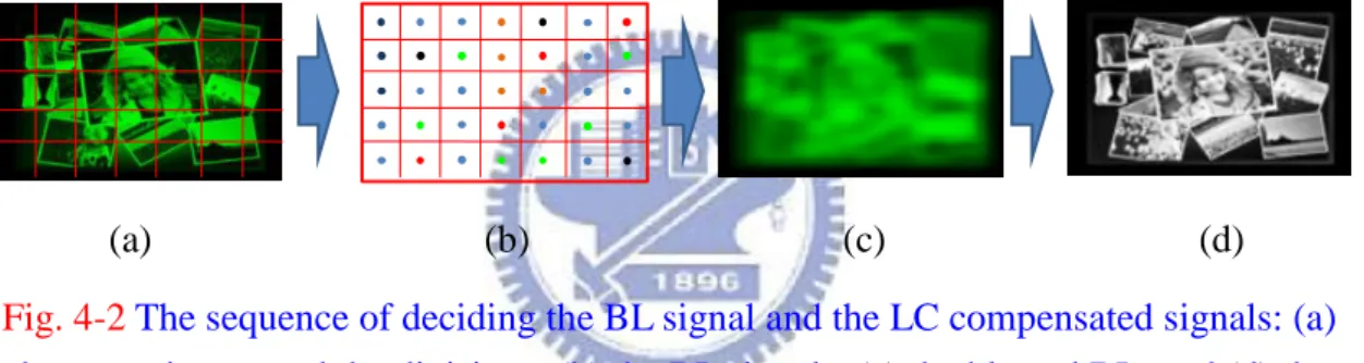
Fig. 4-2 The sequence of deciding the BL signal and the LC compensated signals: (a) the target image and the divisions, (b) the BL signals, (c) the blurred BL, and (d) the LC compensated signals. ... 33
Fig. 4-3 The construction of the picture classifier: (a) the target image and the divisions, and (b) the simpler diagram owning color difference information. ... 33
Fig. 4-4 The examples of the images and the corresponded diagrams. ... 34
Fig. 4-5 The sorting result from the picture classifier: the horizontal axis is the average, and the vertical axis is the standard deviation. ... 34
Fig. 4-6 Thirteen pictures were chosen from the picture classifier. ... 35
Fig. 4-7 The influence of more backlight divisions estimated by the average ΔE... 36
Fig. 4-8 The influence of backlight divisions estimated by the percentage of ΔE>3. . 37
Fig. 4-9 The improvements by the Contrast Dependent Dimming Method in conditions (a) contrast ratio: 270:1, (b) contrast ratio: 110:1, (c) contrast ratio: 35:1, and (d) contrast ratio: 12:1. ... 40
Fig. 4-10 The trend of the improvements. ... 40
x
clipping effect. ... 42
Fig. 4-12 Percentage of ΔE>1 of (a) test images and (b) comparison between with dimming and without dimming. ... 43
Fig. 5-1 Log of contrast ratio VS Image quality estimated by the average ΔE... 45
Fig. 5-2 Log of contrast ratio VS Image quality estimated by the percentage of ΔE>3. ... 46
Fig. 5-3 The experimental setup: the 19” demo panel. ... 47
Fig. 5-4 The gamma curve of the demo panel. ... 48
Fig. 5-5 The experimental flowchart... 49
Fig. 5-6 The psychophysical experiment result. ... 50
Fig. 5-7 Above the red block: The comparison of Cyan_moon between (a) contrast ratio 680:1 and (b) the optimized contrast ratio 70:1. (c) The color difference map. ... 51
Fig. 5-8 In the red block: The comparison of Harbor between (a) contrast ratio 680:1 and (b) the optimized contrast ratio 70:1. (c) The color difference map. ... 51
Fig. 5-9 In the red block: The comparison of Harbor between (a) contrast ratio 680:1 and (b) the optimized contrast ratio 70:1.. (c) The color difference map. ... 52
Fig. 5-10 Below the red block: The comparison of Harbor between (a) contrast ratio 680:1 and (b) the optimized contrast ratio 70:1. (c) The color difference map. ... 52
Fig. 5-11 APLs sampled from around the world [25]. ... 54
xi
Fig. 5-13 The relative optical power results. ... 56
Fig. 5-14 The concepts of (a) the Two Field method and (b) the 120Hz Stencil-FSC. 57
Fig. 5-15 The relative optical power consumption trend of 120Hz Stencil-FSC using different white LED efficiencies. ... 58
Fig. 6-1 The gamma conversion functions: (a) the linear modification, (b) the nonlinear modification. ... 62
1
Chapter 1
Introduction
Liquid crystal display (LCD) is the main technology of display. However, the optical LCD throughput is only 10%. Due to the energy concerns are increasing around world, the low optical throughput issue has become more urgent to be solved. In this chapter, the motivation and the objective of the thesis will be given. The final section of this chapter will detail the organization of the thesis.
1.1 Thin Film Transistor Liquid Crystal Display (TFT-LCD)
Unlike cathode ray tube (CRT), TFT-LCD is not a self-emissive structure and it needs a backlight module. A TFT-LCD is composed of two main components, a backlight module and a liquid crystal cell layer (LC layer). In conventional LCD, the backlight module provides a stable and full-on backlight. The LC layer blocks some light to form an image with contrast.
A backlight module generally consists of a light source, and a set of optical films [1]. Previously, the light source was cold cathode fluorescence lamp (CCFL). CCFL needs mercury to be filled in the glass tube. When adding a high electric field between electrodes at both ends of the glass tube, glow discharge occurs and excites mercury to emit ultraviolet rays. However, mercury vapor has high potential to damage our environment. Thus, CCFL is gradually being replaced by LED light source. In addition to the pollution issue, LED [2] also has higher saturation, longer lifetime, and lower power consumption characteristics than CCFL. The set of optical films, as shown in Fig. 1-1, usually includes a light guide plate, a reflector, diffuser, a brightness
2
enhancement film (BEF). The light guide plate (LGP) guides the light in the normal direction. The reflector raises the light efficiency. The diffuser raises the light uniformity. The BEF collimates the light. The LGP in Fig. 1-1 is a light guide plate guiding the light source from a side direction to a normal direction. Fig. 1-1 is a traditional CCFL backlight module.
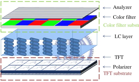
A LC layer consists of two glass substrates as Fig. 1-2 shows, a TFT-array substrate with a polarizer and a color-filter substrate with an analyzer. LC molecules are filled between these two glass substrates. When light emitted from backlight module propagates to the LC panel, the polarizer on the TFT-array substrate changes the light polarization to linear polarization. TFTs, functioning as operators, are three times more numerous than pixels of a display. TFTs control the electric field level within each sub-pixel. Adding different electric fields between the two glass substrates changes LC orientation and forms different phase retardations in each sub-pixel. This phenomenon is due to the LC’s birefringence characteristic, which is LC’s ability to change light polarization states possessing different orientations. When light possessing different polarization states propagates to the analyzer, the analyzer blocks different amounts of light for each sub-pixel. Finally, the color-filter turns white light into red, green, and blue lights and the additive color model gathers the three sub-pixels to color the pixel.
3
Fig. 1-1 A traditional CCFL backlight module.
Fig. 1-2 A liquid crystal panel.
1.2 TFT-LCD Issues
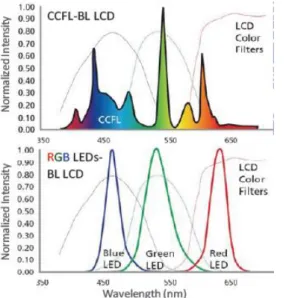
TFT-LCD is currently a widely used and well accepted product but it still has some serious issues that need to be improved. Low color saturation is one of these issues. Because of the wide light spectrum caused by CCFL and imperfect red, green, and blue spectrums caused by color-filters as Fig. 1-3 (a) shows, the three primary colors on the color gamut map are close to each other resulting in a small triangle on the color gamut
prism lens diffuser LGP reflector Lamp reflector CCFL Patterns (elements) Optical films Light source
Analyzer
Color filter
LC layer
TFT
Polarizer
Color filter substrate
4
map which indicates low color saturation as Fig. 1-3 (b) shows [3].
The imperfect dark state is another issue. Before filling in LC cells, a polyimide (PI) layer is evenly printed on the glass substrate to prepare for rubbing process. The rubbing process forms a straight groove on the PI layer, making the LC cells orient in the same direction. However, the rubbing process also restricts the LC cells close to the PI layer from re-orienting by the electric field and causing light leakage. Besides the rubbing process, imperfect-cross polarizers and director fluctuation in LC cells also cause light leakage. Light leakage from LC layer makes images fuzzy and lowers display contrast and image quality.
The low optical throughput is also another issue. When the light propagates through optical forms, polarizer, LC layer, color-filter, and analyzer, the light intensity decays each element by each element as Fig. 1-4 shows. After all, humans can only perceive around 6% light. In the whole light propagation process, the color-filter and the two polarizers waste the most light.
5
(a) Spectra of light sources and color filters (b) Color gamut comperison
Fig. 1-3 (a) Spectra covered by CCFL, LEDs, and typical LCD color filters (b) color gamut comparison between LED backlight and CCFL backlight [3].
Fig. 1-4 Optical throughputs of each element in LCD and the total optical throughput is only around 6% of incident light.
1.3 Motivation and Objective
Liquid crystal display has optical throughput only around 5-8%, which means over 90% of light has been wasted. Ironically, the energy issue has getting more and more serious. Thus, enhancing the optical throughput will have high potential to reduce
x y
TFT~60%
Polarizer~45% LC layer~90% Analyzer~95%
color filter~33% Backlight~70%
~6% of the incident light
6 the power consumption of displays.
To enhance the optical throughput, the color-filter and the two polarizers are key elements. If the color-filter and polarizers can be removed from display, the optical throughput can be increased to around 40%. Based on 120Hz-FSC, this thesis will propose a locally controlled backlight method and simulate images shown by polarizer-free displays. Besides, this thesis will also propose a picture classifier for simulation.
1.4 Organization of This Thesis
This thesis is organized as follows. In chapter 2, Field Sequential Color Liquid Crystal Display (FSC-LCD) which has successfully removed color-filter from LCD will be introduced. A polarizer-free LCD named polymer dispersed liquid crystal (PDLC) and its mechanism and property will be introduced. In chapter 3, a concept of Eco-Display will be given and the LC-dependent Dimming method will be introduced in detail. In chapter 4, a new image classifier for FSC-LCD and for the LC-dependent Dimming method will be introduced. The reason why a new image classifier is needed will be explained. The simulation and discussion from it will be presented in this chapter too. In chapter 5, the experimental result and discussion will be given. Finally, the conclusions and future works will be given in chapter 6.
7
Chapter 2
Prior methods
Researchers have been working on color-filter-less display and polarizer-free display. Field Sequential Color LCD (FSC-LCD) has three times optical throughput without a color filter [4]. However, an issue called color breakup (CBU) reduces the visual comfort and image quality [5]. Also, with higher frame rate, FSC-LCD restricts the response time of liquid crystal. Therefore, Two Field method will be introduced.
In the following, this thesis will introduce the mechanism of PDLC and its properties. Besides displays, a way to evaluate image quality, CIEDE2000, will also be introduced in the final section.
2.1 Color-filter-less Liquid Crystal Display
Field Sequential Color Liquid Crystal Display (FSC-LCD) removes the color-filter. In order to generate a colorful image, the FSC-LCD flashed each color component in sequence using synchronously pulsed colored backlights. In RGB driving method, the FSC-LCD shows red, green, and blue images sequentially as Fig. 2-1 shows. Based on the temporal color mixing phenomena, human vision system will combine those images and feel a colorful image.
The FSC-LCD driving scheme includes three main parts: the TFT addressing, the LC orientation, and the backlight flashing [6]. A frame is divided into three fields. The frame rate is 60Hz the same as the conventional LCD to present people from feeling flicker. Thus, the field rate will be 3 times higher than the frame rate is. In each field, the display has to complete loading data for the whole panel, orientating liquid crystal
8
to the right position, and flashing backlight as shown in Fig. 2-2. After showing the red, green, and blue fields, the inherent temporal color mixing mechanism in human vision system mixes the three fields, and generates a full-color image as Fig. 2-3 shows.
Fig. 2-1 The RGB driving method of FSC-LCD.
Fig. 2-2 The FSC-LCD driving scheme.
Fig. 2-3 Temporal color mixing.
TFT
Polarizer LC layer Analyzer
Backlight Temporal color mixing TFT addressing LC orientation Backlight flashing TFT addressing LC orientation Backlight flashing TFT addressing LC orientation Backlight flashing A field time=5.56msec. A frame time=1/60sec. The display is driven in 60 Hz frame rate
RED field GREEN field BLUE field
RED field
GREEN field
BLUE field Full-colorimage
time Sequentially displayed three field
9
2.1.1 Color Break-up Phenomenon
FSC-LCD is a color filter-less display, it achieves three times higher optical throughput than a conventional LCD. The way FSC-LCD forms a colorful image, sequentially displaying fields, brings itself a serious issue, Color Break-up (CBU). CBU looks as a rainbow blur on the object edge in the image as Fig. 2-4 shows. CBU strongly reduces the image quality and bothers people when they watch TV.
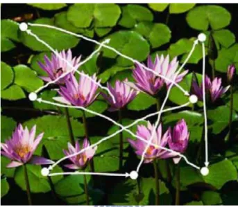
CBU can be typically divided into two types. One is a stationary type which occurs in stationary image. When people watch a display, the human eye performs a sequence of saccades [7] and fixations. Saccade is an action of scanning quickly, as Fig. 2-5 shows, but fixation is an action of gazing at something. The white lines in Fig. 2-5 describe the randomly eye saccade movements. The stationary CBU mechanism is shown in Fig. 2-6 [8][9]. The gray line in Fig. 2-6 (a) is an eye saccade movement. When the eye moves along the gray line, the CBU phenomenon occurs, as shown in Fig. 2-6 (b). The other type of CBU is the dynamic CBU. A dynamic CBU occurs when the eye traces the smoothly moving object. The mismatch of the object’s digital motion and the eye’s analogic motion makes the red, green, and blue fields locate on different places on the retina. The mechanism of CBU is illustrated in Fig. 2-7 [10]. When a white bar moves from left side to right side in a panel, the red, green, and blue fields in the same frame locate at the same horizontal position. However, tracing the white bar is a smooth and analogic motion for the eye, as the blue block in Fig. 2-7 shows. Thus, the edges of the white bar lose some colors and look colorful here as shown in the bottom of Fig. 2-7. The colorful edges are the dynamic CBU.
10
(a) The original image (b) CBU image
Fig. 2-4 A comparison between the original image and CBU image: (a) the original image and (b) CBU image.
Fig. 2-5 The saccade phenomena.
(a) (b)
Fig. 2-6 The stationary CBU mechanism. (a) The image displayed on the FSC panel and the path of a saccade movement (gray line), and (b) static CBU phenomenon.
11
Fig. 2-7 The mechanism of dynamic CBU.
2.1.2 Methods to Suppress CBU
CBU is a serious issue in FSC. Many methods were reported to suppress CBU such as RGBRGB, RGBCY, and RGBKKK [10]. RGBRGB increases the field rate to shrink the colorful edges. RGBCY inserts cyan and yellow fields to reduce color differences among each field and the CBU visibility. RGBKKK which gave the best CBU suppression increases the field rate and inserts black fields to shrink the colorful edges. Both RGBRGB and RGBKKK shrink the colorful edges produced by fields. However, the total CBU area is thinner in RGBKKK. All the methods can suppress CBU effect. However, all of them increased the field rate and reduces the LC response time a lot.
The analogic
motion of the eye
Horizontal position
Ti
m
12
2.1.3 Two Field Method
The FSC-LCD drives LC cells three times or even higher faster than the conventional LCD does. However, the LC cells on the market are hard to response and orient in such a short period. Thus, a method, Two Field method, utilizing the least fields to generate a colorful image was proposed. The LED backlight and local color dimming backlight technique accomplished the Two Field method [11].
The lack of the third primary color field prevents FSC-LCD from showing a full-color image. Thus, the Two Field method has to incorporate the local color dimming backlight technique to show three primary colors in two fields. The replacement of the LED backlight achieves the local color dimming backlight technique. In the first field, the Two Field method shows red information and part of blue information by locally controlling and lighting up red and blue LEDs. In the second field, Two Field method shows green information and the remaining blue information as Fig. 2-8 shows. Therefore, the Two Field method can merely use two fields to show the three primary colors. The reduced number of fields reduces a field time and gains more time for LC.
The CBU visibility comparison is compared in Fig. 2-9. Conventional FSC show strong CBU phenomena. The color band edges in convention FSC, as shown in Fig. 2-9 (a), are induced by the primary colors which are easy to be observed. However, the color band edges in Two Field method are mixed colors. Human vision system is less sensitive for the mixed colors as shown is Fig. 2-9. Thus, the CBU visibility of the Two Field is lower than the convention FSC.
13
Fig. 2-8 RGB driving method versus Two Field method.
(a) (b)
Fig. 2-9 CBU comparison (a) conventional FSC, and (b) Two Field method.
2.2 Polarizer-free LCD
A PDLC is a type of the polarizer-free LCD which does not need polarizers to show contrast. The PDLC has a continuously changing optical property from the off state to the on state. The optical property results from a refractive index mismatch between droplets of liquid crystal and a polymer matrix. In this section, the thesis will
RB1-field GB2-field
RGB driving method
14
introduce the basic mechanism of the PDLC and show how to utilize the optical property for a display.
2.2.1 Polymer-dispersed Liquid Crystal Display (PDLC display)
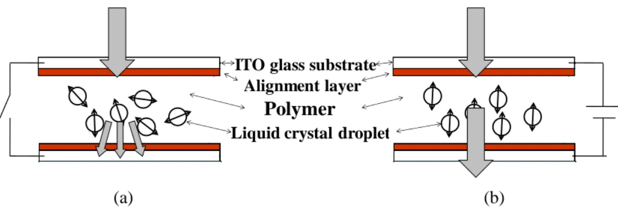
The PDLC is a polymer matrix with liquid crystal droplets dispersed in it [12][13]. When no electric field is applied to the PDLC film, the optical axis of each droplet is randomly oriented as Fig. 2-10 (a) shows. Therefore, the incident light sees different refractive index values depended on the optical axis of each droplet. Moreover, the refractive index of the polymer matrix is also different from the refractive index of the liquid crystal droplet. Finally, the incident light scatters as a result from the refractive index mismatches and represents an opaque state. When an electric field is applied to PDLC film, the optical axis of each droplet reorients to the same direction parallel to the electric field as Fig. 2-10 (b) shows. Thus, the incident light sees only a refractive index value of liquid crystal cells. Furthermore, if the refractive index value of the chosen polymer is the same as the refractive index value of the liquid crystal droplets, the vertical incident light regards the PDLC film as an isotropic media, propagates through the film directly and represents a transparent state.
The applications of PDLC films are various such as vision product and displays. PDLC displays have an inherent advantage that they don’t require expensive polarizers which waste over 50% of the incident light to show contrast.
15
(a) (b)
Fig. 2-10 A mechanism showing how PDLC works from a voltage-off state to a voltage-on state: (a) the PDLC without voltage where light is scattered because of the refractive index mismatch, and (b) the PDLC with voltage where light passes through
display.
2.2.2 Dye-doped PDLC
A dye-doped PDLC film is a PDLC film within some dye doped [14][15]. Besides the scattering effect of the PDLC, the dye-doped PDLC further absorbs light to achieve a better dark state. In the dye-doped PDLC, the low polymer concentration forms a polymer network instead of a polymer matrix to scatter light. The low polymer concentration accelerates the orientation of the LC molecules and reduces the long response time of the conventional PDLC. The concentration of dyes dominates the dark state. When the concentration of the dyes becomes high, the more dyes can absorb more light in the dark state and result in a better dark state. However, the LC cells will need more energy to rotate the dyes and the more energy will result in a high operation voltage.
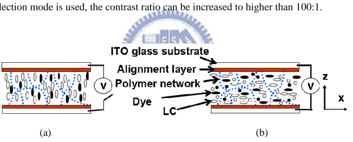
The mechanism of a dye-doped PDLC film is shown in Fig. 2-11. In a voltage-off state, the LC cells align vertically and the light only sees the short optical axis. When the refractive indexes of the LC cells and the polymer network match, the light does not scatter. Moreover, due to the dichroic characteristic of the dyes, the
ITO glass substrate Alignment layer
Polymer
16
vertically aligned dye molecules absorb little light. In a voltage-on state, the electricity reorients the LC cells and the LC cells reorient the dyes. The dyes which are randomly dispersed on the x-y plane absorb light owning any polarization direction because the long axes of the dyes are parallel to the polarization direction of light. Thus, the dye-doped PDLC appears a dark state. The scattering effect extends the light propagation length and increase the chance for the dyes to absorb light. Therefore, the cooperation of the scattering effect and the absorption effect generates a better dark state.
The transmittance of the bright state is around 70%. Some research results indicate that the dye-doped PDLC film has a contrast ratio around 10-20. If a reflection mode is used, the contrast ratio can be increased to higher than 100:1.
(a) (b)
Fig. 2-11 A mechanism showing how dye-doped PDLC works from a voltage-off state to a voltage-on state: (a) the voltage-off state and (b) voltage-on state.
2.3 Color Matching Model and CIEDE2000
To evaluate the proposed method in this thesis, a standard index is necessary. Commission Internationale de I’Eclairage (CIE) works for color standards. In the following section, this thesis will start from a color matching model and introduce
17
color spaces. Followed by utilizing the standards to evaluate the proposed method and compare an original image and a processed image.
2.3.1 Color Matching Model
The color matching model was proposed by CIE because scientists wanted to define colors. The cone cells and the rod cells in eyes absorb colors and the lighting information. The three L, M, and S cones dominate color information but the three stimuli of the three cones could not be detected.
In the CIE RGB color model [16], the tri-stimulus is the intensities of three primary stimuli, R (700nm), G (546.1nm), and B (435.8nm). By tuning the intensities, the CIE RGB could find a mixture ratio of the primary colors representing the same color as the test color does. After testing all the colors, a CIE RGB color matching function was got as Fig. 2-12 shows. The CIE XYZ color model [16] can further modify the CIE RGB. By linear transformation, the CIE XYZ changes the CIE RGB color matching function into a totally positive function which is called CIE XYZ color matching function as Fig. 2-13. The tri-stimulus values can be got by Eq. 2-1.
(2-1)
18
Fig. 2-12 The CIE 1931 RGB color matching function.
Fig. 2-13 The CIE 1931 XYZ color matching function.
2.3.2 CIEDE2000 for Evaluating Color Difference
The CIE LAB color space is a color-opponent space fitting the human vision system. By compressing the CIE XYZ nonlinearly, three new dimensions, L, a, and b, respectively representing lightness, and the two color-opponent dimensions comprises the CIE LAB. The CIE LAB has much better uniformity than the CIE XYZ. The
19
non-linear transformation from the CIE XYZ to the CIE LAB is described from Eq. 2-2~Eq. 2-6. Because of different visual sensibilities in different lighting conditions, the CIE LAB also takes the light source, Xn, Yn, and Zn, into consideration. The calculated distances as Eq. 2-8 shows on the CIE LAB color space can represent color differences. Generally, a color different around 2.3 corresponds to “just noticeable difference.”
Based on the CIE LAB, CIE further proposed two formulae, the CIE94 [17] and the CIEDE2000 [18]-[20], to refine color differences description of the CIE LAB since fails to charge large color differences and the color differences in the blue region. Considering chroma and hue, the CIEDE2000 is better in describing color differences. A hue rotation term (RT) in Eq. 2-9 deals with the problematic blue region.
The color difference of the CIEDE2000 is described as Eq. 2-9 shows. This thesis will utilize the CIEDE2000 to evaluate color differences between an original image and a processed image in proposed method.
(2-2) (2-3) (2-4) (2-5) (2-6) (2-7) where (2-8) (2-9)
20 where
=1+0.045 , and
: Differences of luminance, chroma, and hue : Parametric factors of luminance, chroma, and hue : Weighting functions of luminance, chroma, and hue
: Rotation function
2.4 Summary
The energy issue in the world is getting more and more serious. Ironically, as a widely used device, LCD is not energy-efficient. The optical throughput of conventional LCD is below than 10%. That is over 90% of optical energy has been wasted. To enhance the optical throughput, the LCD needs to throw away the color filter and the polarizers. The FSC LCD and the Two Field method do not need a color filter while PDLC does not need polarizers. If we can apply the FSC concept to PDLC film, the LCD can throw both color filter and polarizer away.
21
Chapter 3
Eco-Display without Color-filter & Polarizer
This thesis will propose a method to achieve an Eco-Display. This Eco-Display does not need a color-filter and two polarizers, as Fig. 3-1 shows. Without color-filter and polarizers, the optical throughput is greatly enhanced from 5% to 37%. Moreover, less material processing is also friendlier to the environment. Thus, it will be an “Eco-Display.”
Fig. 3-1 The hardware structure of the Eco-display.
3.1 Concept
One of the standards to judge a display is contrast ratio. Although polarizer-free LCDs have many advantages, the contrast ratio is still too low for human vision system. To increase the contrast, the LED backlight [2] must be introduced because its point-like light source can be controlled individually. Previously, the backlight was the full-on CCFL and even a black image still needed full-on backlight, as Fig. 3-2
TFT~60%
LC layer~90%
Backlight~70%
Backlight dimming
~37% of the incident light22
shows. If the LC molecules and the polarizers are not perfect, light leakage will be observed. However, an individually controllable backlight, LED backlight, can tune its backlight intensities division by division according to image details. If the image is a white block in the center with a black background, an individually controllable backlight only turns on the center divisions covering the white block as Fig. 3-3 shows. Even though the LC molecules and the polarizers may not be perfect, the turned off backlight does not produce a light leakage. Thus, the LED backlight increases the image contrast ratio and reduces the light leakage. This system is named the “High Dynamic Range” (HDR) system [21][22]. The HDR saves power and has high contrast advantages.
The HDR system is necessary to achieve the Eco-display. To reduce the low contrast issue of polarizer-free LCDs, the HDR tech contributes to this issue. Therefore, a new backlight dimming method for low contrast polarizer-free LCDs is needed. The next section will propose a dimming method which increases contrast and maintains image quality.
(a) Input image (b) CCFL backlight (c) Low contrast LC (d) Output image Fig. 3-2 A schema of the low contrast display with full-on backlight: (a) target image,
(b) traditional full-on CCFL backlight, (c) low contrast LC layer (it can be PDLC or EWD or other materials), and (d) the final image.
23
(a) Input image (b) LED backlight (c) Low contrast LC (d) Output image Fig. 3-3 A schema of the LED backlight display: (a) target image, (b) individually
controllable LED backlight, (c) low contrast LC layer (it depends on the material used), and (d) the final image with higher contrast.
3.2 Contrast Dependent Dimming Method
The Contrast Dependent Dimming Method is a very flexible dimming method. Depending on the different types of the LC layer with different contrasts, the Contrast Dependent Dimming Method adjusts itself to fit the different contrast performances of the LC layers.
Previously the objective of the Contrast Dependent Dimming Method was maintaining image quality; that is, the objective was to keep the output image the same as the input image. However, because the LED resolution is lower than the LC resolution, one backlight dimming ratio in one division cannot fit many different LC signals in one division as Eq. 3-1 shows.
Therefore, this thesis replaced the original objective with “maintaining the light intensity uniformity in the divisions.” As the contrast ratio becomes lower, the light leakage in dimmer pixels lights up the image and reduces image quality as Fig. 3-4 shows. Provided that the backlight intensity is uniform in each division, the total transmitted light intensity of a normal display with high contrast LC equals the summation of the transmittances of all the pixels in the division as Eq. 3-2 shows.
24
(a) The original image (b) the low contrast image
Fig. 3-4 A comparison between the original image and the low contrast image.
On the other hand, the LC layer’s contrast limitation excludes LC signals lower than the LC layer’s darkest state. , , and are beyond the LC layer’s dark limitation. Thus, for these kinds of LCs, the digital numbers are set as the LC layer’s lowest transmittance. The remaining calculation is similar to a normal display calculation as Eq. 3-3 shows. Fig. 3-5 shows a diagram of the and calculation. The represents the ideal intensity while the represents the intensity of low contrast. In Fig. 3-5, the histogram processing settles the LC signals in a division. The red circle in the bottom chart stands for the lowest transmittance. After histogram processing, the signals below the red circle gather to the red circle and generate a number of pixels at it. Finally, to achieve the same division intensity, the Contrast Dependent Dimming Method is defined as
/ . (3-1) (3-2) where
represents for the total transmitted light intensity of a normal display in
a division.
The LCs are the digital signals of LC cells. N is the number of pixels in a division.
25 (3-3) where
represents for the total transmitted light intensity of a polarizer-free
display in a division.
The LCs are the digital signals of LC cells. N is the number of pixels in a division.
, , and stand for the dark limitation of the LC layer; thus,
, ,
and
equal the lowest transmittance of the LC layer.
Fig. 3-5 A diagram to interpret the calculation of and .
3.3 Contrast Dependent Dimming Method Applied to FSC
In this section, the reason why the Contrast Dependent Dimming Method is needed and how we applied it to FSC will be introduced in detail. An algorithm of applying the Contrast Dependent Dimming Method to the FSC will then be shown. Where the Contrast Dependent Dimming Method works in an image will be illustrated in a real case.
Gray level pixels histogram High contrast LC Low contrast LC histogram Gray level pixels
The lowest transmittance
∑Xi*Yi=I
division26
3.3.1 The Applied FSC method—The Two Field
To realize FSC concept based on PDLC film, the response time of LC cells must be taken into consideration. The response time of the PDLC is longer than the conventional LC. Thus, the methods such as RGBRGB, and RGBKKK [10] which need higher frame rate than the conventional LCD does are useless. Therefore, this thesis incorporates the Two Field method which has the least fields.
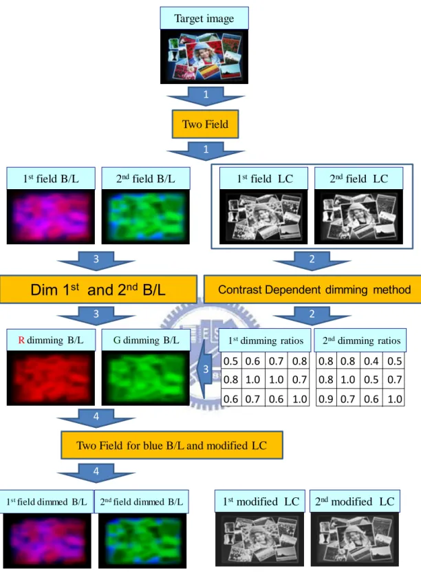
The flowchart of applying the Contrast Dependent Dimming Method to the Two Field method is shown in Fig. 3-6. First, the Two Field method generates the first field backlight, the first LC signal, the second field backlight, and the second LC signal. Second, the Contrast Dependent Dimming Method calculates a dimming ratio for each division according to the lowest transmittance limitation of the PDLC and the LC signals. Third, the first backlight and the second backlight are dimmed based on the dimming ratios from the second step. Fourth, this thesis uses the backward process of the Two Field method to calculate the third backlight (In this case, the third backlight is the blue backlight.). Finally, the modified LC signals are reproduced by the conventional LC signal calculation. The first field dimmed backlight, the second field dimmed backlight, the first modified LC signal, and the second modified LC signal are the final backlights and the LC signals.
27
Fig. 3-6 A flowchart showing how Contrast Dependent Dimming Method works with Two Field method
Target image
1
Two Field
1stfield B/L 2ndfield B/L 1stfield LC 2ndfield LC
1
2
Contrast Dependent dimming method
0.5 0.8 0.6 1.0 1.0 1.0 0.8 0.6 0.6 0.7 0.7 0.7 2 0.8 0.8 0.8 1.0 0.5 1.0 0.5 0.6 0.9 0.7 0.7 0.4 2nddimming ratios 1stdimming ratios Rdimming B/L Gdimming B/L 3 3
Dim 1
stand 2
ndB/L
3 4Two Field for blue B/L and modified LC
4
28
3.3.2 The Self Adjustment
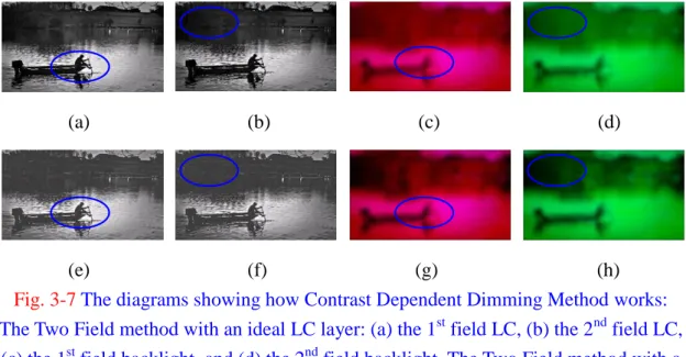
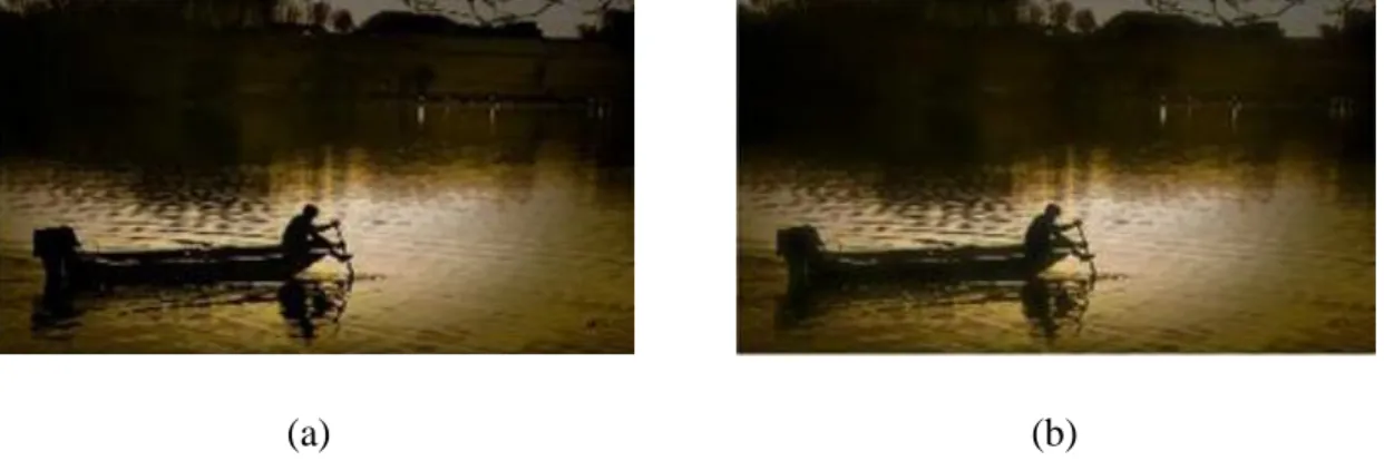
To make a clearer interpretation, Fig. 3-7 shows how the Contrast Dependent Dimming Method works on the backlights. A 45x80 backlight division was assumed. Fig. 3-5 (a), (b), (c), and (d) show the backlights and the LC signals of the Two Field method with an ideal LC layer. Fig. 3-7 (e), (f), (g) and (h) show the backlights and the LC signals of the Two Field method with a low contrast LC layer. A 25:1 contrast ratio was assumed. The blue circles circle the dark part in LC signals. When the contrast ratio becomes low, the LC signals in the blue circles become brighter. Therefore, to keep the brightness the same, the Contrast Dependent Dimming Method dims the backlights in the blue circles. However, outside the blue circles such as the river, the Contrast Dependent Dimming Method does not dim the backlight as much as the backlights in the blue circles because the LC signals can keep the image details. A comparison between the Two Field method with an ideal LC layer and the Two Field method with a low contrast LC layer is shown in Fig. 3-8. Although a little light leakage can be seen, most of the image details have been kept.
(a) (b) (c) (d)
(e) (f) (g) (h) Fig. 3-7 The diagrams showing how Contrast Dependent Dimming Method works:
The Two Field method with an ideal LC layer: (a) the 1st field LC, (b) the 2nd field LC,
(c) the 1st field backlight, and (d) the 2nd field backlight. The Two Field method with a
low contrast LC layer: (e) the 1st field LC, (f) the 2nd field LC, (g) the 1st field
29
(a) (b)
Fig. 3-8 Simulation results of (a) The Two Field method with an ideal LC layer, and (b) The Two Field method with a low contrast LC layer.
3.4 Summary
The Eco-display is a kind of display which does not need a color filter and polarizers. Based on the PDLC film, to further remove the color filter, this thesis adopt the Two Field method for the reason that the response time of the PDLC film is low. Simply applying Two Field method to PDLC film results in low contrast and losing image details in the darkness.
The Contrast Dependent Dimming Method was proposed to increase the contrast ratio and image details in the darkness. The Contrast Dependent Dimming Method can adjust itself for different PDLC films owning different contrast ratios and even for different image details in different divisions.
30
Chapter 4
Analysis of the Contrast Dependent Dimming
Method
The analysis of the Contrast Dependent Dimming Method will be done in this chapter. This thesis will propose a picture classifier to classify the data base and choose some pictures for simulation. Using the chosen picture, the optimized backlight division will be decided. In the following, the improvement by the Contrast Dependent Dimming Method will be estimated. Finally, the issues of the Contrast Dependent Dimming Method will be discussed.
4.1 Picture Classifier
The factors affect FSC-LCD’s performance are two. One is a mismatch of the LED resolution and the LC resolution. The other is light leakage from the neighbor divisions. Based on the two reasons, this thesis will incorporate the hue for the classifier. In the following sections, this thesis will introduce the hue, the details of the construction of the classifier, and the pictures chosen for simulation.
4.1.1 Hue
The hue which describes the kind of color such as red, green, and blue was from the Munsell color system [23]. The system was developed originally by an American artist, Albert Munsell in 1905, and the scale was refined and renotated by the Colorimetry Committee of the Optical Society of America (OSA) in the late 1930s. The Munsell color system uses cylindrical coordinates to specify colors as shown in
31
Fig. 4-1 (a). The coordinates are hue as the circumferential angle, value (lightness) as the ordinate, and chroma as the radius.
The Munsell color system selected red (R), yellow (Y), green (G), blue (B), and purple (P) as five principle hues and spaced the principle hues equally around the hue circle. The colors YR, GY, BG, PB, and RP are inserted between each two principle hues. Moreover, the Munsell color system further divided the space between a principle hue and an intermediate hue into ten hues. Totally, a hundred hues were established. Forty hues are shown in Fig. 4-1 (b). The numerical calculation of hue is described by Eq. 4-1 and Eq. 4-2.
(4-1)
(4-2)
(a) (b)
Fig. 4-1 The Munsell color system: (a) the color solid for the Munsell color system, and (b) the Munsell hues [24].
4.1.2 The Construction of the Picture Classifier
To build a picture classifier suitable for FSC-LCD, knowing the issues which affect the image quality is necessary. In FSC-LCD, because the LED resolution is
32
always much lower than the LC resolution, a LED backlight signal needs to take care of many LC signals. The sequence of deciding the BL signal and the LC compensated signals is shown in Fig. 4-2. A green image is taken as an example. The location of LED backlights divides the image into divisions. In Fig. 4-2 (b), the LED backlight in each division is decided by the average, the square root of average, or the one-third power of the pixels in the division. By using Eq. 4-3 the LC compensated signals are calculated.
Thus, one of the issues affecting the image quality occurs when the colors in a division diverge greatly. If the colors in a division diverge greatly, the LED backlight will not be suitable for every pixel in either LED decision way and result in bad image quality. Another issue may occur in the blurring part. When the LED backlight in a division differs from the LED backlight in a neighbor division a lot, the compensated LC signal may not well compensate the light leakage from the neighbor divisions and result in bad image quality. Both the issues are related to color differences with the neighbors.
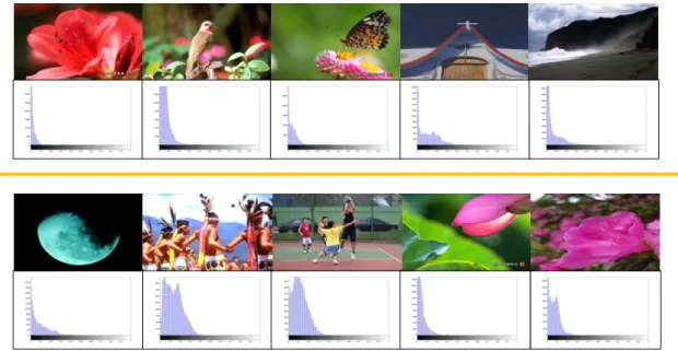
Based on the color differences, the thesis simplifies the images into simpler diagrams owning color difference information as Fig. 4-3 shows. In Fig. 4-3 (a), the RGB coordinate is transformed to the hue circumferential angle which represents the kind of color. Each pixel in the image has its neighbors. The red center represents the pixel and the yellow neighbors represent the red center’s neighbors as Fig. 4-3 (a) shows. Next, we average the differences between the yellow neighbors and the red center for the color difference characteristic of the red center. Thus, each pixel has its color difference characteristic. Finally, a histogram of the pixels is the simpler diagram owning color difference information.
33
In Fig. 4-4, according to different color difference information, each image has its own diagram. This thesis utilizes the average and the standard deviation as two standards to sort the data base. The sorting result is shown in Fig. 4-5. The bottom two figures are with low standard deviations while the top two figures are with high standard deviations. The left two figures are with low averages while the right two figures are with high averages.
(4-3) where
The I represents the image intensity, the BL is the backlight intensity, and the LC is the LC signal.
(a) (b) (c) (d) Fig. 4-2 The sequence of deciding the BL signal and the LC compensated signals: (a)
the target image and the divisions, (b) the BL signals, (c) the blurred BL, and (d) the LC compensated signals.
(a) (b)
Fig. 4-3 The construction of the picture classifier: (a) the target image and the divisions, and (b) the simpler diagram owning color difference information.
RGB Hue Yellow neighbors Histogram
34
Fig. 4-4 The examples of the images and the corresponded diagrams.
Fig. 4-5 The sorting result from the picture classifier: the horizontal axis is the average, and the vertical axis is the standard deviation.
4.1.3 The Pictures Chosen for Simulation
Besides the picture classifier, this thesis also consults the lightness which is an
0 0.001 0.002 0.003 0.004 0.005 0.006 0.007 0.008 0.009 0.01 0 0.05 0.1 0.15
hue
Average S ta nda rd de vi a ti on35
issue affecting the image quality in a polarizer-free display, the human face, the skin tone, and the sunset. Eventually, thirteen pictures were chosen including colorful images, plane images, sunset images, and images with skin as Fig. 4-6 shows. In the top column, from left to right are Canoe, Harbor, Soccer, and Candle. In the middle column, from left to right are Palace, Desert, Airplane, and Motorcycles. In the bottom column, from left to right are Girl, Cyan_moon, Beach, Pharos, and Woman.
Fig. 4-6 Thirteen pictures were chosen from the picture classifier.
4.2 Simulation
In this section, some simulation results will be shown. The optimized backlight division of the Two Field method was 45x80. To further remove the polarizers, more backlight divisions may be needed. Next, this thesis will simulate the images with different LC contrast ratios and compare the images processed by the Contrast Dependent Dimming Method with the Two Field method and the images processed by no Contrast Dependent Dimming Method with the Two Field method. In the last part, a brief discussion of backlight division will be shown.
36
4.2.1 Backlight Division
Before simulation, the decision of the backlight division is necessary. Based on the optimized backlight division, 45x80, more backlight divisions were simulated according to difference gray level ranges. The influence of more backlight divisions were estimated by using the average ΔE and the percentage of ΔE>3. The result of both the average ΔE and the percentage of ΔE>3 shows the more backlight divisions improve the image quality. However, the improvement is really tiny. In the results of the average ΔE, an increase of backlight division from 45x80 to 72x128 only results in 0.2 or less improvement as shown in Fig. 4-7. In the results of the percentage of ΔE>3, an increase of backlight division from 45x80 to 72x128 results in less than 3% improvement as shown in Fig. 4-8. Thus, we can infer that the influence of backlight divisions saturates before 45x80. Therefore, in the following simulation, the backlight division, 45x80 was assumed.
Fig. 4-7 The influence of more backlight divisions estimated by the average ΔE.
0 0.2 0.4 0.6 0.8 1 1.2 [45,80] [54,96] [63,112] [72,128]
A
ve
ra
ge
Δ
E
Backlight division discussion
10-255 20-255 30-255 40-255
37
Fig. 4-8 The influence of backlight divisions estimated by the percentage of ΔE>3.
4.2.2 With the Contrast Dependent Dimming Method VS
Without the Contrast Dependent Dimming Method
In this section, the effect of Contrast Dependent Dimming Method will be shown by simulating the images with different LC contrast ratios and comparing the images processed by the Contrast Dependent Dimming Method with the Two Field method and the images processed by no Contrast Dependent Dimming Method with the Two Field method.
To know the improvement by the Contrast Dependent Dimming Method, this thesis compares the color difference between the Two Field method and the low contrast Two Field method using the Contrast Dependent Dimming Method with the color difference between the Two Field method and the low contrast Two Field method without using the Contrast Dependent Dimming Method. The average ΔE which takes care of all pixels may blur the effect of the Contrast Dependent Dimming Method which only dims certain part of an image. Thus, the adopted standards are the
0 2 4 6 8 10 12 [45,80] [54,96] [63,112] [72,128]
P
er
ce
nt
ag
e
of
Δ
E
>3
Backlight division discussion
10-255 20-255 30-255 40-255
38
percentage of ΔE>3 and ΔE>1. The improvement was defined as Eq. 4-4 shows. The results for four contrast ratios, 270, 110, 35, and 12, are shown in Fig. 4-9. The contrast ratios correspond to the LC gray level ranges, 20-255, 30-255, 50-255, and 80-255. The blue bars indicate the results using a criterion of ΔE>3 and the red bars indicate the results using another criterion of a percentage of ΔE>1.
When the contrast ratio is high such as Fig. 4-9 (a), the improvements are not clear. However, when the contrast ratio becomes lower, a clearer improvement can be seen. Some of the improvements are minus because of the clipping in brightness which will be discussed in 4.3.
(4-4) (a) -20% -10% 0% 10% 20% 30% 40% 50% 60% 70% 80% 90% 100% Im p rov em en t
Contrast ratio: 270:1
39 (b) (c) -20% -10% 0% 10% 20% 30% 40% 50% 60% 70% 80% 90% 100%
Im
p
rove
m
en
t
Contrast ratio: 110:1
Percenta ge of ΔE>3 Percenta ge of ΔE>1-20% -10% 0% 10% 20% 30% 40% 50% 60% 70% 80% 90% 100% Im p rov em en t
Contrast ratio: 35:1
40 (d)
Fig. 4-9 The improvements by the Contrast Dependent Dimming Method in conditions (a) contrast ratio: 270:1, (b) contrast ratio: 110:1, (c) contrast ratio: 35:1,
and (d) contrast ratio: 12:1.
Fig. 4-10 The trend of the improvements.
-20% -10% 0% 10% 20% 30% 40% 50% 60% 70% 80% 90% Im p rov em en t
Contrast ratio: 12:1
Percenta ge of ΔE>3 Percenta ge of ΔE>1
0% 5% 10% 15% 20% 25% 30% 35% 1 1.5 2 2.5 3 A v e r a g e i m p r o v e m e n t (%)
Contrast ratio (log)
The trend of the improvements
Percenta ge of ΔE>3 Percenta ge of ΔE>141
The trends of the improvements are two growth curves as shown in Fig. 4-10. Since the lower contrast ratio results in more light leakage, the backlight dimming saves more pixels and results in a better improvement. Thus, both the average improvements of ΔE>1 and ΔE>3 becomes higher when the contrast ratio becomes lower. Due to the saturation of ΔE>1 which will be discussed in 4.3, the trend of improvement of ΔE>1 saturates at the end. However, the positive improvements indicate the Contrast Dependent Dimming Method improves the image quality.
4.3 Discussion-- Clipping and Saturation
In this section, both the issues, the clipping in brightness and the saturation at the end of the improvement trend, will be discussed in detail.
4.3.1 The Clipping in Brightness
The clipping effect occurs when the LC signals diverge greatly. The dark LC signals make the Contrast Dependent Dimming Method dim the backlight. The bright LC signals keep the Contrast Dependent Dimming Method from dimming the backlight. However, when both the extremities exist in a division, the clipping effect occurs. The original gamma conversion function outputs the gray level the same as the input gray level as shown in Fig. 4-11 (a). When the backlight gets dimmed, the gamma conversion function outputs the gray level higher than the input gray level as shown in Fig. 4-11 (b). Thus, the gamma conversion function clips the pixels owning higher than the 255 gray level after the conversion. However, the simulation in the previous section shows the Contrast Dependent Dimming Method improves the image quality in most of the situations.
42
(a) (b)
Fig. 4-11 The gamma conversion functions: (a) the original function, and (b) the clipping effect.
4.3.2 The Saturation
Some test images saturate in the result of percentage of ΔE>1 such as Cyan_moon and Candle as Fig. 4-12 (a) shows. When the log of contrast ratio becomes lower than 1.5, ΔE>1 appears on most of the boundary between bright area and dark area. Thus, the decrease of contrast ratio does not produce more ΔE>1. Due to the ΔE>1 saturation from some test images, the growth rate of percentage of ΔE>1 becomes lower in average, as shown in Fig. 4-12 (b). Therefore, the decreased growth rate of percentage of ΔE>1 affects the trend of the improvement and results in the saturation, as shown in Fig. 4-10.
0 50 100 150 200 250 300 0 50 100 150 200 250 O u tp u t gr ay le ve l
Input gray level
Original 0 50 100 150 200 250 300 0 50 100 150 200 250 O u tp u t gr ay l e ve l
Input gray level
Clipping
43
(a) (b)
Fig. 4-12 Percentage of ΔE>1 of (a) test images and (b) comparison between with dimming and without dimming.
4.4 Summary
The picture classifier is designed for the FSC-LCDs based on the hue and the lightness characteristics. Thirteen pictures were chosen from the picture classifier. The chosen pictures own different characteristics such as colorfulness, brightness, gradient colors, and human faces. The used backlight division is 45x80. The improvement results show when the contrast ratio becomes lower, the Contrast Dependent Dimming Method works more. Although some clipping effects occur in the bright area, the trend of improvements shows all the improvements are positive on average.
0 10 20 30 40 50 60 70 80 1 1.5 2 2.5 3 P er ce n ta g e o f Δ E > 1
Contrast ratio (log)
Percentage of ΔE>1
Ca noe Ha rbor Pha ros Soccer Cya n_moon Pa la ce Desert Motorcycles Airpla ne Bea ch Girl Woma n Ca ndle
0 5 10 15 20 25 30 35 1 1.5 2 2.5 3 P e r c e n tage of Δ E > 1
Contrast ratio (log)
Percentage of ΔE>1
44
Chapter 5
Optimization and Power
According to the picture labrary and the backlight division from the previous chapter, an optimized contrast ratio and an optimized threshold of the color difference will be decided in this chapter. The optimization process will start from the simulation of the color differences. For determining the optimized contrast ratio, a psychophysical experiment will be tested. The optimized contrast ratio will correspond to the optimized threshold. Based on the optimized contrast ratio, this thesis will discuss the power issue and show an ultimate power saving from the Eco-display.
5.1 The Simulation of the color difference
Different gray level ranges of the LC film were assumed. The LC gray level ranges, 0-255, 10-255, 20-255, 30-255, 40-255, 50-255, 60-255, 70-255, and 80-255 correspond to the contrast ratios, ideal, 1200, 270, 110, 60, 35, 25, 17, and 12. The image quality will be estimated by the average ΔE and the percentage of ΔE larger than 3. The ΔE larger than 3 is the least value that human vision system can feel.
The image quality estimated by the average ΔE is shown in Fig. 5-1. Some pictures possessing few image details and low image contrast (not the contrast ratio of the LC film of the horizontal axis) keep their slopes low. These curves of the pictures, such as Woman, Pharos, Beach, and Dessert, do not rise steeply. Some of the pictures possessing either complicated image details or high image contrast, such as Harbor, Girl, Cyan_moon, Candle, Canoe, Girl, and Soccer, keep their color differences below
45
than 1.2. However, in the results of these pictures, a slightly risen slope can be seen. For the rest pictures, they possess really complicated image details and high image contrast, such as Motorcycles, and Palace. The slopes of these pictures rise as the contrast ratio becomes lower.
The simulation result using the percentage of ΔE larger than 3, as shown in Fig. 5-2, is similar to the simulation result using the average ΔE. However, by only analyzing the simulation results, the optimized contrast ratio and the optimized
threshold of the color difference are still unknown. Thus, in the following section, this thesis will do a psychophysical experiment to find the optimized contrast ratio.
Fig. 5-1 Log of contrast ratio VS Image quality estimated by the average ΔE.
0 0.5 1 1.5 2 2.5 1 1.5 2 2.5 3 A v er a g e Δ E
Contrast ratio (log)
Contrast ratio VS Image quality
Ca noe Ha rbor Pha ros Soccer Cya n_moon Pa la ce Desert Motorcycles Ca ndle Bea ch Girl Woma n Ca ndle